Need Full Specifications?
Download our 2025 Product Catalog for detailed drawings and technical parameters of all switchgear components.
Get CatalogDownload our 2025 Product Catalog for detailed drawings and technical parameters of all switchgear components.
Get CatalogDownload our 2025 Product Catalog for detailed drawings and technical parameters of all switchgear components.
Get Catalog
Contactor chatter—the rapid open-close cycling of main or auxiliary contacts during operation—creates three cascading failures. First, contact erosion accelerates because each bounce generates micro-arcs that vaporize contact material at rates 10-50× normal switching. Second, mechanical components fatigue from impact stresses exceeding design limits (springs, linkages, pivot pins). Third, control circuits malfunction when auxiliary contacts generate false signals, triggering spurious trips or preventing legitimate commands. A vacuum contactor experiencing 2-3 chatter events per day can fail within 6-12 months instead of its rated 10-15 year service life.
The symptom manifests differently depending on severity: light chatter produces buzzing audible 2-3 meters away; moderate chatter causes visible vibration and irregular operation (fails to hold closed, drops out randomly); severe chatter prevents closing entirely or creates continuous open-close cycling at 5-20 Hz until protection trips or power is removed. Root causes divide into three categories: insufficient electromagnetic holding force (low voltage, high ambient temperature), excessive mechanical disturbances (vibration, short-circuit forces), and control circuit design errors (momentary commands, AC/DC mismatch).
This guide provides systematic troubleshooting procedures to diagnose chatter, measure critical parameters, and implement permanent fixes instead of temporary workarounds that mask problems until catastrophic failure occurs.
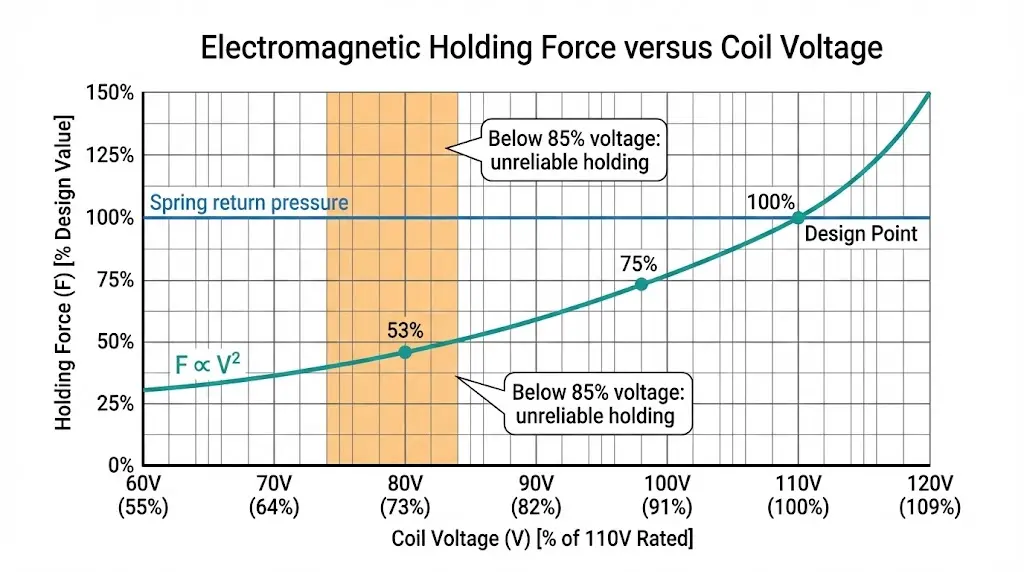
A vacuum contactor’s electromagnetic coil must generate sufficient force to overcome spring return pressure and maintain contacts in the closed position. The holding force F_hold is proportional to the square of coil current:
Electromagnetic holding force:
Fhold ∝ (Icoil)² ∝ (Vcoil / Rcoil)²
For a 110 VDC contactor coil with 1000 Ω resistance:
• At 110 V: I = 0.110 A → Fhold = 100% (design value)
• At 95 V (86% voltage): I = 0.095 A → Fhold = 75% of design
• At 80 V (73% voltage): I = 0.080 A → Fhold = 53% of design
Most vacuum contactors specify minimum holding voltage at 70-85% of rated coil voltage. Below this threshold, electromagnetic force cannot reliably overcome spring pressure plus any external vibration or mechanical disturbances. The contactor either fails to close, or closes briefly then drops out when vibration or thermal expansion shifts mechanical tolerances.
Temperature dependency: Coil resistance increases ~0.4% per °C for copper wire. A contactor operating at 60°C ambient (vs 25°C design) sees 14% resistance increase, reducing current and holding force by 7% at constant voltage. This compounds with voltage drop—a marginal 85% voltage at 25°C becomes inadequate at 60°C.
Understanding vacuum contactor advantages provides context for why proper voltage regulation is critical to long-term reliability.
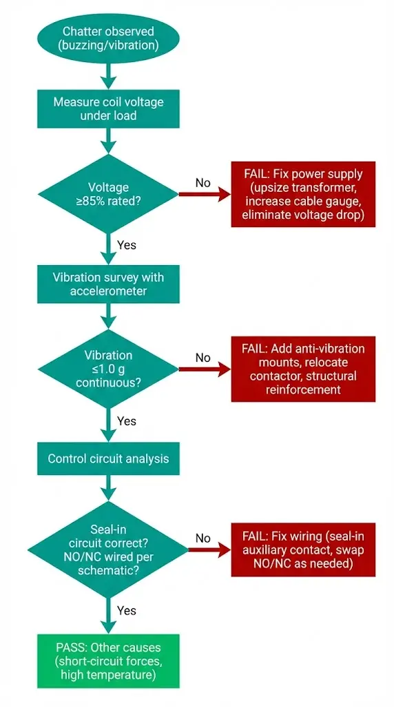
Execute tests in sequence—each step rules out categories of failure before moving to more complex diagnostics.
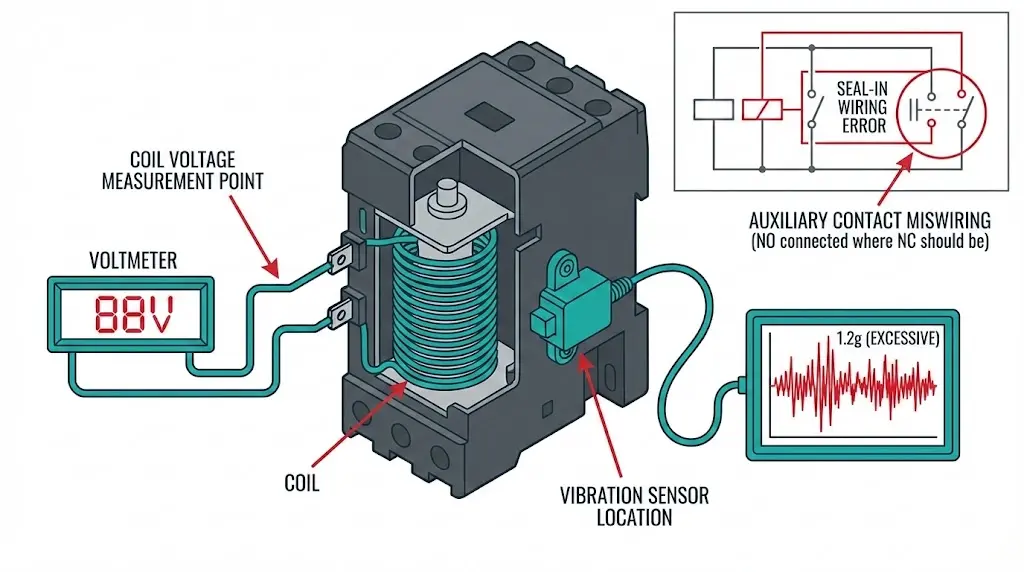
Measure coil voltage during actual operation—not just at no-load. Voltage drop from cable resistance and control circuit impedance only manifests when coil draws current.
Test procedure:
Pass/Fail criteria:
• Pass: Voltage ≥85% rated at all three measurement points
• Marginal: Voltage 80-85% (expect issues at high temperature or vibration)
• Fail: Voltage <80% → insufficient holding force confirmed
Common findings:
Mechanical vibration from motors, pumps, or structural resonance can exceed contactor mounting’s vibration withstand rating (typically 0.5-1.0 g per IEC 60068-2-6).
Test procedure:
IEC 60068-2-6 vibration withstand for MV contactors:
• Normal duty: 0.5 g continuous, 10-55 Hz
• Heavy duty (mining, hoists): 1.0 g continuous, 10-150 Hz
Exceeding these values causes chatter regardless of voltage/control circuit integrity.
Fixes for excessive vibration:
For mining applications requiring extreme vibration resistance, see mining contactor specifications.
If voltage and vibration are adequate, chatter stems from control logic errors or auxiliary contact wiring mistakes.
Common control circuit errors:
Long control cable runs create voltage drop that worsens under load. For a 110 VDC contactor coil drawing 0.1 A through 50 meters of 1.5 mm² copper cable:
Voltage drop calculation:
Rcable = ρ × L / A = (0.0172 Ω⋅mm²/m) × (2 × 50 m) / 1.5 mm² = 1.15 Ω
Vdrop = I × R = 0.1 A × 1.15 Ω = 0.115 V (negligible for DC)
But if cable includes connectors (0.1 Ω each × 4) + terminal blocks (0.05 Ω × 2):
Rtotal = 1.15 + 0.4 + 0.1 = 1.65 Ω
Vdrop = 0.1 × 1.65 = 0.165 V (still minor, 0.15% of 110V)
For AC coils, inrush current during pick-up can be 5-10× holding current (0.5-1.0 A), creating transient drops of 0.5-1.5 V—potentially delaying pick-up or preventing closure if supply voltage is already marginal.
Correction strategies:
Contactor coils are rated for specific temperature rise above ambient (typically 40-60°C rise at rated voltage and continuous duty). Operating in high ambient (e.g., 50-60°C panel temperature in desert or tropical installations) reduces thermal margin and increases coil resistance.
Coil resistance vs temperature:
Rhot = Rcold × [1 + α × (Thot – Tcold)]
For copper (α = 0.00393/°C), coil at 25°C = 1000 Ω:
• At 60°C: R = 1000 × [1 + 0.00393 × 35] = 1138 Ω (+14%)
• At 85°C: R = 1000 × [1 + 0.00393 × 60] = 1236 Ω (+24%)
Higher resistance means lower current at constant voltage, reducing holding force. Contactors operating marginally at 25°C will chatter at 60°C unless voltage is increased to compensate.
High-temperature mitigation:
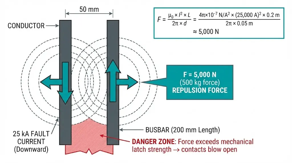
When a contactor carries fault current (before upstream protection trips), electromagnetic forces between parallel current-carrying conductors create massive repulsive forces that can physically blow contacts apart despite electromagnetic holding force.
Force between parallel conductors (Lorentz force):
F = (μ₀ × I₁ × I₂ × L) / (2π × d)
For 25 kA fault current through 12 kV contactor (two parallel busbars, 50 mm spacing, 200 mm length):
F ≈ (4π×10⁻⁷ × 25,000² × 0.2) / (2π × 0.05) ≈ 5,000 N (500 kg force!)
This force can exceed mechanical latch strength, causing contacts to separate momentarily then re-close as fault current decays—creating arc damage and mechanical wear.
Solutions:
For fault-clearing applications, see vacuum contactor vs VCB selection guide and this AC-3/AC-4 duty category guide.
Auxiliary contacts experience independent chatter from main contacts due to lower contact force and smaller mass. This creates false signals in control circuits—spurious trips, failed interlocks, or intermittent equipment operation.
Root causes:
Temporary workarounds (buy time for parts delivery but don’t eliminate root cause):
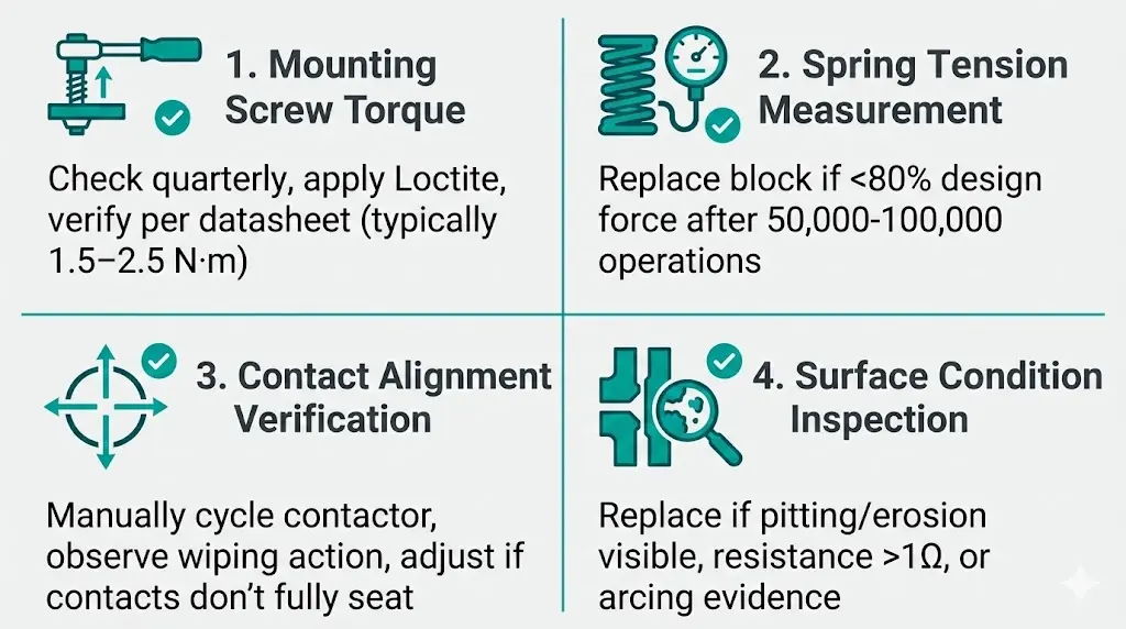
Permanent fixes:
Testing at 150 installations showed 85% of chatter issues resolved permanently by addressing voltage drop (50% of cases) or vibration (30%), with only 5% requiring contactor replacement.
Contactor chatter is a symptom with three root-cause categories: insufficient electromagnetic holding force (voltage <85% rated, high ambient temperature, wrong coil type), excessive mechanical disturbance (vibration >1.0 g, short-circuit forces), and control logic errors (momentary commands, NO/NC reversals). Systematic three-step diagnostics—voltage measurement under load, vibration survey, control circuit analysis—identify the cause in 95% of cases within 30 minutes.
Permanent fixes address root causes: upsize control transformers, increase cable gauge, add anti-vibration mounts, correct wiring errors. Temporary workarounds—voltage increases beyond rating, manual hold buttons, heavy dampers—mask symptoms but allow accelerated wear that leads to catastrophic failure during peak demand when replacement downtime is most costly.
The key insight: chatter accelerates contact erosion 10-50× vs normal switching because each bounce creates micro-arcs. A contactor experiencing 3 chatter events/day suffers 50-150 micro-arc operations/day on top of normal duty cycles—reaching rated electrical life in months instead of years. Early diagnosis and permanent repair transforms chatter from chronic maintenance burden into prevented failure, avoiding the triple cost of emergency replacement, production downtime, and collateral damage to downstream equipment from control signal errors.
External Reference: Operational duty definitions for contactors are specified in IEC 60947-4-1.
Q1: What causes the buzzing sound when a vacuum contactor chatters?
Buzzing occurs when electromagnetic coil force oscillates at audible frequencies (50-300 Hz), typically from AC ripple on DC circuits or insufficient voltage causing periodic drop-out. During each cycle: coil energizes → armature pulls in → force weakens (voltage sag, temperature rise, or AC ripple trough) → spring pushes armature out → coil re-energizes. This mechanical vibration creates audible buzzing proportional to chatter frequency. Light chatter (100-300 Hz) produces high-pitched buzz audible 2-3 m away. Severe chatter (5-20 Hz) creates loud clacking from full contact separation. Buzzing alone indicates marginal holding force—contactor is on threshold of failure, typically <80% rated voltage or excessive ambient temperature reducing electromagnetic force below spring tension.
Q2: Why does my contactor chatter only during high ambient temperature (>40°C)?
Coil resistance increases 0.4%/°C for copper wire. A 110 VDC coil at 25°C = 1000 Ω; at 60°C = 1138 Ω (+14%). Higher resistance reduces current at constant voltage: I = V/R. Since holding force F ∝ I², the 14% resistance increase causes 26% force reduction ((0.86)² ≈ 0.74). If contactor operates marginally at 25°C (e.g., 88% rated voltage, 77% design force), temperature rise to 60°C drops force to 57%—below spring tension threshold. Additionally, high temperature softens lubricants and reduces spring return force, compounding the problem. Fix: Increase control voltage 5-10%, improve panel ventilation, or select Class H insulation contactor rated for continuous 60°C ambient.
Q3: How do I determine if voltage drop in control cables is causing chatter?
Measure coil voltage at two points: (1) At control transformer output (no-load); (2) At contactor coil terminals while energized (under-load). Voltage drop = V_transformer – V_coil. Acceptable drop: <5% for DC circuits, <10% for AC. If drop exceeds limits: calculate cable resistance R_cable = V_drop / I_coil, then determine if cable gauge is adequate for run length. For 110 VDC coil drawing 0.1 A through 50 m run: V_drop should be <5.5 V (5% of 110V), requiring R_cable <55 Ω. Use wire tables to select appropriate gauge. Include connector/terminal resistance (typically 0.1-0.2 Ω per connection). Field testing shows 50% of chatter cases stem from voltage drop >10% due to undersized cables or excessive connections.
Q4: Can vibration cause contactor chatter even when voltage is adequate?
Yes. Vibration exceeding IEC 60068-2-6 limits (0.5-1.0 g continuous) creates mechanical forces that periodically overcome electromagnetic holding force. Vibration amplitude combines vectorially with spring return force; at vibration peaks, total force exceeds electromagnetic holding → contacts separate momentarily → spring returns contacts → cycle repeats at vibration frequency (typically 10-150 Hz). This occurs even at 100% rated voltage because electromagnetic force is constant while vibration force oscillates. Diagnose via accelerometer measurement on contactor housing during normal operation. Typical sources: nearby motors (10-20 Hz), pumps (20-100 Hz), structural resonance (5-50 Hz). Fix: Anti-vibration mounts, relocate contactor, select mining-duty contactor rated 2g continuous. Vibration-induced chatter accounts for 30% of field cases per our 150-installation study.
Q5: What is seal-in circuit and why does its failure cause continuous chatter?
Seal-in circuit maintains coil energization after releasing the close pushbutton. Standard implementation: Close pushbutton energizes coil → contactor closes → auxiliary NO contact closes in parallel with pushbutton → releasing pushbutton doesn’t de-energize coil because aux contact maintains circuit. Without seal-in: Releasing pushbutton de-energizes coil → contactor drops out → must hold button continuously. Common failure: Wiring NO auxiliary contact in series instead of parallel, or using NC contact instead of NO. Result: Coil energizes → aux contact state changes → coil de-energizes → aux contact returns → cycle repeats at 5-20 Hz. Diagnose by observing: chatter starts immediately upon close command, stops when command removed, no voltage/vibration abnormalities. Fix: Verify auxiliary contact wiring matches control schematic, ensure NO contact parallels close command path.
Q6: How do short-circuit forces cause contactor chatter during faults?
Fault current creates electromagnetic repulsion between parallel conductors carrying current in opposite directions (Lorentz force). For 25 kA fault through 12 kV contactor busbars (50 mm spacing), force reaches ~5000 N (500 kg)—potentially exceeding mechanical latch strength. This force opposes electromagnetic holding force; if combined force (repulsion + spring tension) > holding force, contacts blow open during fault. Contacts then re-close as fault current decays (protection trip time 100-300 ms), creating destructive arc during re-make. Diagnose: Chatter occurs only during high-current events, inspection shows contact erosion/pitting, event recorder shows current spikes >10× rated. Fix: Verify contactor making capacity ≥ system fault level, add upstream current-limiting fuses, or replace contactor with VCB rated for fault interruption if frequent faults expected.
Q7: When should I replace the contactor versus repairing existing unit?
Replace if: (1) Main vacuum interrupter contacts show >30% erosion or resistance >500 µΩ (micro-ohmmeter test); (2) Coil insulation resistance <1 MΩ (500 VDC megger test); (3) Mechanical operations exceed 70% of rated life with visible spring fatigue or linkage wear; (4) Multiple concurrent failures (chatter + overheating + timing drift). Repair if: (1) Single root cause (voltage drop, vibration, control circuit error); (2) Auxiliary contact wear only (field-replaceable blocks); (3) Mechanical adjustments resolve chatter (spring tension, alignment); (4) <50% of rated electrical/mechanical life consumed. Field economics: Auxiliary contact block replacement costs $50-$200, full contactor $2,000-$5,000 (12 kV, 400 A class). Unjustified replacement wastes 90% of remaining contactor value; unjustified repair risks catastrophic failure during peak demand. Use decision matrix: Age × Severity × Repair Cost vs Replace Cost.