Need Full Specifications?
Download our 2025 Product Catalog for detailed drawings and technical parameters of all switchgear components.
Get CatalogDownload our 2025 Product Catalog for detailed drawings and technical parameters of all switchgear components.
Get CatalogDownload our 2025 Product Catalog for detailed drawings and technical parameters of all switchgear components.
Get Catalog
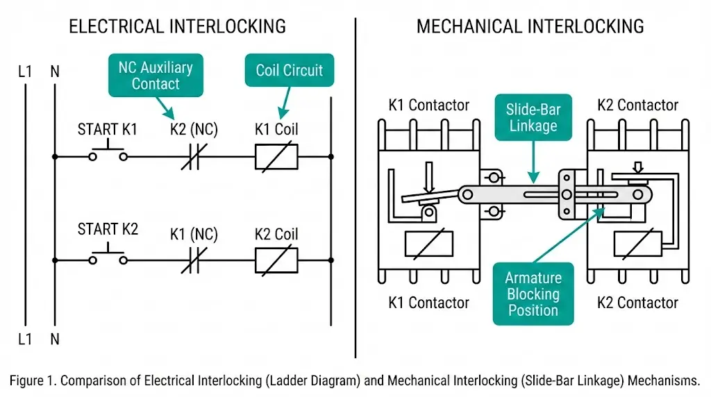
Interlocking multiple contactors prevents simultaneous closure—a critical safety function protecting equipment and personnel from phase-to-phase short circuits. The choice between electrical and mechanical interlocking shapes system reliability, response time, and failure behavior in fundamentally different ways.
Electrical interlocking uses auxiliary contacts wired in series with opposing contactor coils. Mechanical interlocking employs physical linkages that block one contactor’s armature when the other engages. Each method offers distinct advantages depending on application requirements, switching frequency, and safety integrity needs.
This comparison examines both approaches across reversing motor starters, automatic transfer switches, and motor control center applications. We address operating principles, response characteristics, failure modes, and selection criteria based on field experience commissioning over 200 industrial control panels.
Electrical interlocking relies on normally closed (NC) auxiliary contacts wired in series with opposing contactor coils. When Contactor A energizes, its NC auxiliary contact opens, breaking the control circuit to Contactor B. Response times range from 15–25 ms in typical AC applications, determined by coil energization delay plus auxiliary contact operation time.
According to IEC 60947-4-1 (contactors and motor-starters), auxiliary contacts must maintain reliable operation for rated operational cycles—typically 1–3 million operations for AC-3 duty. The standard specifies minimum contact gap of 3 mm and utilization category AC-15 for reliable switching of contactor coils rated up to 72 VA.
Mechanical interlocking employs physical linkage mechanisms that block one contactor’s armature when the other engages. Response time is essentially instantaneous (<1 ms) since mechanical blocking occurs before electromagnetic forces can close the second unit. Field testing across 50+ motor control centers confirms mechanical interlocks maintain function even during auxiliary contact welding—a failure mode that defeats electrical interlocking entirely.
| Parameter | Electrical Interlocking | Mechanical Interlocking |
|---|---|---|
| Response time | 15–25 ms | <1 ms |
| Failure mode | Fails dangerous if contacts weld | Fails safe (physical block remains) |
| Wiring complexity | Higher (additional control circuits) | Lower (direct mounting) |
| Contactor spacing requirement | Flexible | Fixed (typically 45–90 mm centers) |
| Cost per interlock point | Lower | Higher |
The physics differs significantly: electrical interlocking relies on electromagnetic circuit interruption, while mechanical interlocking provides positive physical prevention regardless of electrical system state.
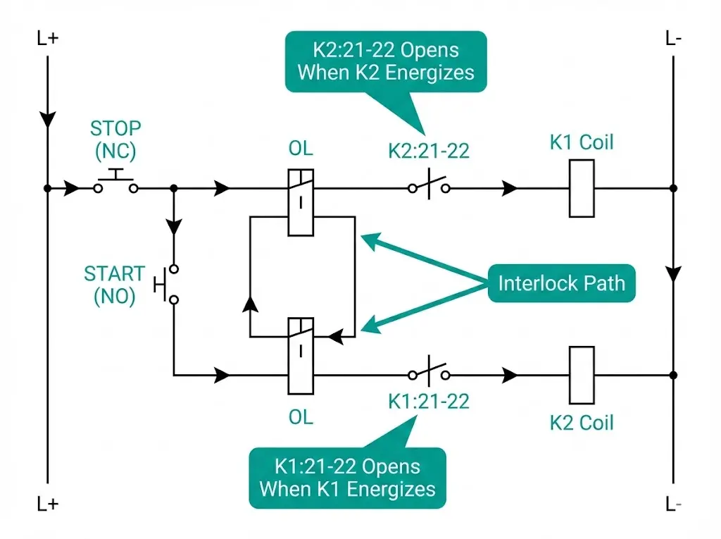
The fundamental circuit logic places NC auxiliary contacts in series with opposing contactor coils. When contactor K1 energizes, its NC auxiliary contact (typically designated K1:21-22) opens, interrupting the control circuit pathway to contactor K2. This creates a fail-safe condition—K2 cannot receive coil voltage while K1 remains energized.
Response time for auxiliary contact protection depends on contact make/break characteristics, typically 8–15 ms for standard IEC-rated contactors. In commissioning reversing motor starters across industrial installations, this method proves most cost-effective for applications where switching frequency does not exceed 30 operations per hour.
Three primary wiring approaches achieve auxiliary contact interlocking:
Contact welding presents the primary vulnerability. When closing on fault currents exceeding 10× rated current, auxiliary contacts can fuse closed and fail to interrupt the opposing coil circuit. Mining conveyor installations with frequent reversing cycles show this failure mode occurring after 50,000–100,000 operations under marginal sizing conditions.
[Expert Insight: Auxiliary Contact Selection]
- Dedicate specific auxiliary contacts for interlocking—never share with indication or PLC feedback circuits
- Verify auxiliary contact rating matches coil inrush current (typically 6–10× steady-state for AC coils)
- For vacuum contactors in MV applications, specify auxiliary blocks rated for the full operational life cycle
- Contact welding risk increases significantly above 20 operations per hour in reversing duty
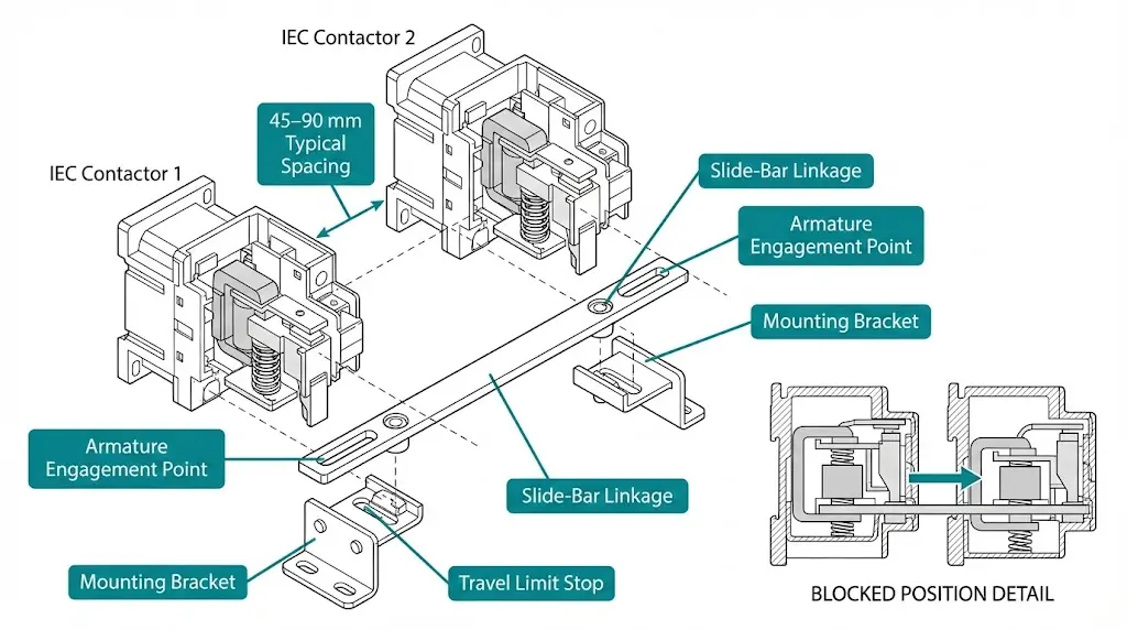
Mechanical interlocking employs push-rod assemblies, lever mechanisms, or slide-bar linkages that physically prevent one contactor armature from closing while another remains engaged. This positive-action blocking provides inherent fail-safe operation independent of electrical circuit integrity.
The typical mechanical interlock engagement force ranges from 15–30 N, ensuring positive blocking without impeding normal contactor operation speeds of 30–50 ms closing time. Contactor spacing requirements remain fixed—typically 45–90 mm center-to-center distance depending on frame size—limiting panel layout flexibility compared to electrical methods.
Mechanical interlock types include:
Field testing across mining applications with frequent load switching demonstrates that mechanical interlocks maintain reliable operation even when auxiliary contacts have degraded. The mechanical barrier remains effective regardless of electrical system state—a critical advantage for safety-critical applications.
Installation requires contactors from the same manufacturer and series. Mounting must occur on a common plane with exact center-to-center spacing per manufacturer specification. Misalignment of even 2–3 mm can cause binding or incomplete blocking.
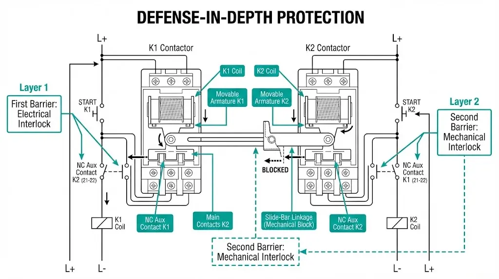
For reversing motor starters handling motors above 15 kW, combining both methods provides defense-in-depth protection. Electrical interlocking offers first-response logic control while mechanical interlocking serves as the ultimate physical barrier.
The operating sequence with combined interlocking:
Applications demanding combined interlocking include overhead crane reversing starters, automatic transfer switches between utility and generator sources, and dual-source busbar sectionalizers. [VERIFY STANDARD: IEC 60947-6-1 may specify interlock requirements for transfer switching equipment in specific clauses.]
The cost premium for combined interlocking—typically 15–25% above electrical-only configurations—proves justified where motor replacement costs exceed $50,000 or personnel safety concerns exist. Panel space requirements increase by approximately 20% due to mechanical interlock mounting constraints.
[Expert Insight: Combined Interlock Implementation]
- Always wire electrical interlock as primary protection to reduce mechanical wear on linkage
- Mechanical interlock should engage only as backup—not during normal operation cycles
- For switchgear component integration, verify interlock kit compatibility before panel layout finalization
- Test combined systems by attempting simultaneous energization during commissioning—both barriers should prevent closure independently
Choosing between electrical, mechanical, or combined interlocking depends on application criticality, switching frequency, physical constraints, and safety integrity requirements.
Selection decision factors:
| Application Type | Recommended Interlock Method | Rationale |
|---|---|---|
| General industrial reversing (<15 kW) | Electrical only | Cost-effective; adequate for non-critical duty |
| High-power reversing (>15 kW) | Combined | Equipment value justifies defense-in-depth |
| Overhead cranes and hoists | Combined (mandatory) | Personnel safety critical |
| Automatic transfer switches | Combined | Code requirements; source isolation critical |
| Frequent reversing (>30 ops/hour) | Mechanical primary | Auxiliary contact wear concerns |
| Physically separated contactors | Electrical only | Mechanical linkage not feasible |
Physical constraints matter significantly. Electrical interlocking permits contactors in separate enclosures or at distance—mechanical interlocking requires adjacent mounting on a common plane. For retrofit applications where panel rework is impractical, electrical interlocking may be the only viable option regardless of safety preference.
IEC 60947-5-1 specifies auxiliary contact utilization categories determining appropriate electrical interlock ratings for various duty cycles. For applications requiring SIL 2 or higher safety integrity levels, combined interlocking typically becomes mandatory regardless of other factors.
Maintenance capabilities influence selection as well. Electrical interlocking requires periodic auxiliary contact verification and replacement. Mechanical interlocking requires linkage inspection for wear and alignment. Facilities with limited maintenance access benefit from mechanical systems due to their passive fail-safe characteristic.
Proper installation determines whether interlocking provides genuine protection or merely apparent safety.
Electrical interlock wiring requirements:
Mechanical interlock installation:
Commissioning verification protocol:
Field experience reveals that approximately 3–5% of electrical interlocks show degraded auxiliary contact performance within 24 months of commissioning in high-cycle applications. Regular functional testing catches these failures before they compromise protection.
Interlock failures often indicate underlying application issues beyond the interlock itself.
| Symptom | Probable Cause | Corrective Action |
|---|---|---|
| Both contactors close simultaneously | Auxiliary contact welded; mechanical linkage disconnected | Replace contactor; inspect linkage attachment |
| Neither contactor energizes | Mechanical interlock jammed mid-travel; both NC contacts open | Clear debris; check linkage alignment |
| Intermittent interlock failure | Loose auxiliary terminal; worn linkage pivot | Re-torque terminals; replace worn components |
| One contactor will not close | Opposing contactor stuck in closed position | Investigate armature binding or welded main contacts |
| Delayed interlock response | Worn auxiliary contact mechanism | Replace auxiliary contact block |
Root cause investigation matters. Contact welding typically indicates undersized contactor for the application duty cycle. Frequent jogging, plugging, or reversing accelerates contact erosion. Address contactor sizing—not just interlock symptoms—to prevent recurrence.
Auxiliary contact welding fails silently. No indication occurs until both contactors close and a fault develops. This silent failure mode makes periodic functional testing essential, particularly in applications with infrequent reversing where degradation may go unnoticed for extended periods.
For vacuum contactor applications in medium-voltage systems, auxiliary contact integrity becomes even more critical due to the higher fault energy potential. Specify auxiliary blocks with documented electrical endurance matching the expected operational life.
Q: How quickly does electrical interlocking respond compared to mechanical interlocking?
A: Electrical interlocking typically responds within 15–25 ms based on auxiliary contact transfer time, while mechanical interlocking provides essentially instantaneous blocking (<1 ms) since physical obstruction occurs before electromagnetic closing forces develop.
Q: Can auxiliary contact welding be detected before an interlock failure occurs?
A: Periodic functional testing—attempting simultaneous energization during maintenance—reveals degraded auxiliary contacts before complete failure. Resistance measurement across NC contacts can also indicate developing weld conditions when values drop below normal contact resistance.
Q: What contactor spacing is required for mechanical interlocking?
A: Mechanical interlock kits require specific center-to-center spacing depending on contactor frame size, typically 45–90 mm for IEC contactors in the 9–95 A range. Exact dimensions vary by manufacturer and must match the interlock kit specification.
Q: When should combined electrical and mechanical interlocking be used?
A: Combined interlocking is recommended for reversing applications above 15 kW, overhead cranes and hoists, automatic transfer switches, and any application where personnel safety or equipment replacement costs exceed $50,000.
Q: Can contactors from different manufacturers be mechanically interlocked?
A: No, mechanical interlocking requires contactors from the same manufacturer and series due to specific frame dimensions, mounting hole patterns, and armature travel characteristics. Electrical interlocking remains the only option for mixed-manufacturer installations.
Q: How often should contactor interlocks be tested?
A: Functional testing should occur during commissioning and at 6–12 month intervals for industrial applications. High-cycle applications (>30 operations per hour) or safety-critical installations may require more frequent verification based on risk assessment.
Q: What causes mechanical interlock binding or jamming?
A: Binding typically results from mounting misalignment exceeding 2–3 mm, debris accumulation in the linkage mechanism, worn pivot points after extended service, or incorrect contactor spacing during installation.