Need Full Specifications?
Download our 2025 Product Catalog for detailed drawings and technical parameters of all switchgear components.
Get CatalogDownload our 2025 Product Catalog for detailed drawings and technical parameters of all switchgear components.
Get CatalogDownload our 2025 Product Catalog for detailed drawings and technical parameters of all switchgear components.
Get Catalog
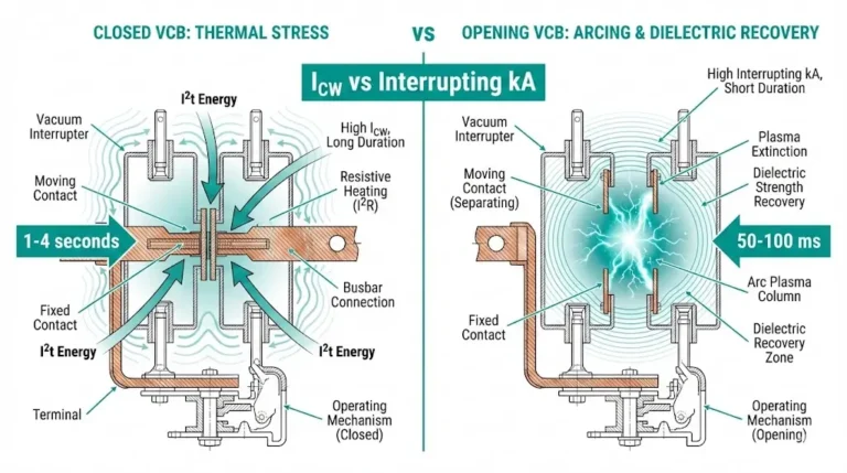
Current chopping occurs when a vacuum circuit breaker forces premature arc extinction before the natural current zero—generating switching overvoltages that disproportionately damage small inductive loads. This counterintuitive phenomenon explains why a 50 kW motor often suffers more severe transient stress than a 500 kW unit on the same switchgear.
In field investigations across 200+ medium-voltage industrial facilities, we’ve documented transient overvoltages exceeding 5 per unit on motors rated below 100 kW, while identical vacuum circuit breakers switching larger loads produced transients under 2.5 per unit. Understanding this mechanism—and implementing targeted mitigation—prevents unexplained insulation failures that plague small transformer and motor installations.
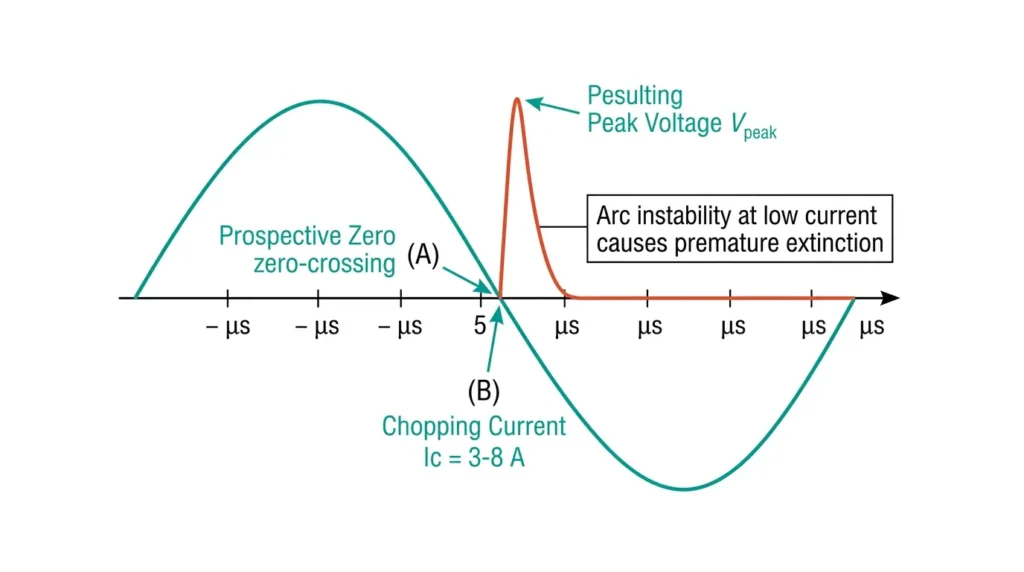
The physics begins at contact separation. As CuCr (copper-chromium) contacts part inside a vacuum interrupter, the arc relies entirely on metal vapor evaporated from contact surfaces. At currents above 10 A, sufficient vapor floods the gap to maintain stable plasma until the natural current zero. Below 5–8 A, vapor production becomes insufficient. The arc starves and collapses prematurely.
This premature extinction is current chopping.
The instant chopping occurs, current through load inductance drops to zero within nanoseconds. Inductance resists such abrupt changes, generating a voltage spike governed by V = L × (di/dt). With di/dt approaching infinity, transients can reach tens of kilovolts.
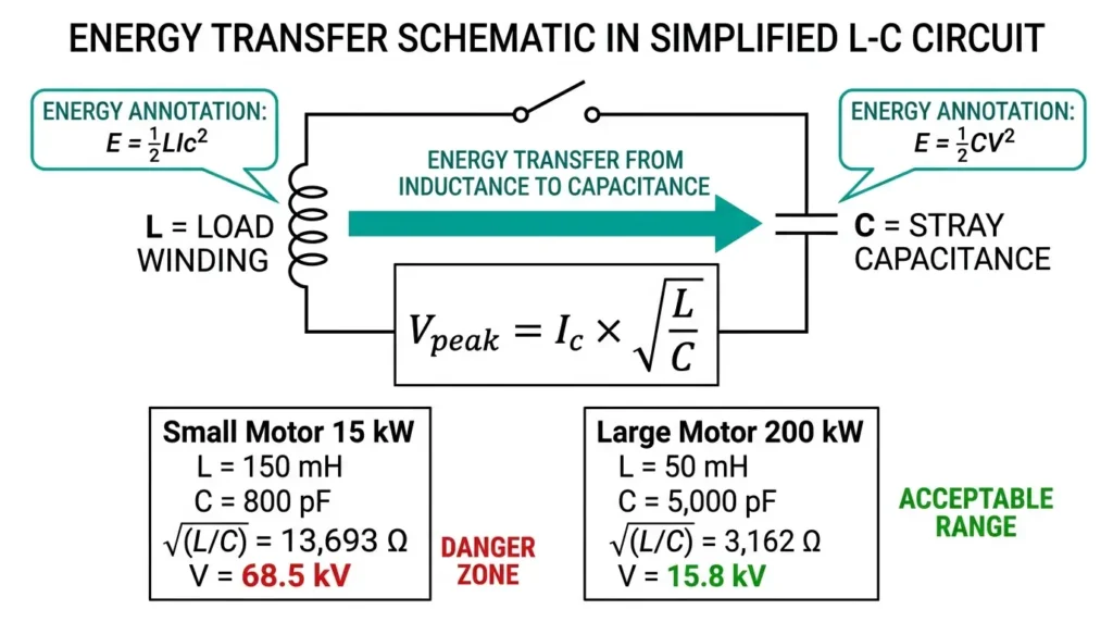
The resulting overvoltage follows energy conservation: magnetic energy stored in inductance (½LIch²) converts to capacitive energy (½CV²). Solving for voltage yields: Vpeak = Ich × √(L/C), where Ich represents chopping current (typically 3–8 A for CuCr contacts), L is load inductance, and C is effective circuit capacitance.
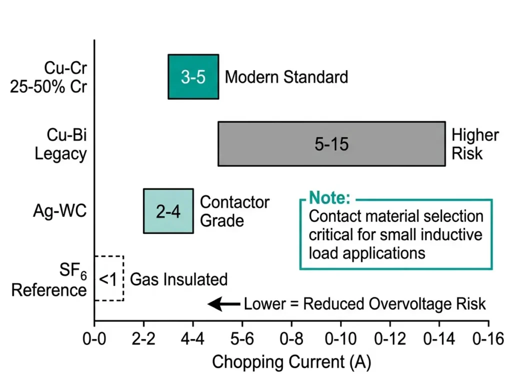
Modern CuCr contacts with 25–50% chromium content achieve chopping currents of 3–5 A—a significant improvement over legacy copper-bismuth materials that chopped at 5–15 A. Yet even these optimized values create problems for vulnerable loads.
The overvoltage equation reveals the critical insight: V_peak is proportional to √(L/C). Small inductive loads present high inductance relative to minimal stray capacitance, producing dangerous L/C ratios.
Consider two real scenarios from our field measurements:
Small motor (15 kW at no-load):
This transient approaches the motor’s 75 kV BIL rating—a dangerously narrow margin from a routine switching event.
Large motor (200 kW):
The larger motor experiences less than one-quarter the overvoltage despite identical chopping current. Higher winding capacitance and typically longer cable runs provide natural damping that small loads lack.
Field observations confirm this relationship. Unloaded dry-type transformers below 100 kVA routinely experience transients of 4–6 per unit during vacuum switching, while larger oil-filled units see only 2–3 per unit under identical conditions.
[Expert Insight: Field Diagnostic Patterns]
Certain applications consistently appear in our failure investigations. Recognizing these high-risk scenarios enables proactive protection.
Unloaded and lightly loaded motors draw only magnetizing current—typically 2–8 A—falling directly within the chopping current range. Turn-to-turn insulation represents the weakest point in the system, with BIL ratings lower than line-to-ground insulation. Repeated start/stop cycles cause cumulative degradation that eventually results in inter-turn flashover.
Dry-type transformers present a double vulnerability. No-load magnetizing current runs 1–3% of rated current, and resin-encapsulated construction provides less inherent capacitance than oil-filled designs. Building service transformers and industrial process transformers switched daily for load management face accelerated aging.
Shunt reactors represent the classic worst-case application: pure inductive load with minimal resistive damping. These are typically specified with dedicated surge protection from initial design.
Arc furnace transformers experience frequent switching cycles during electrode positioning and batch changes. Variable load means operation regularly passes through low-current regions where chopping occurs.
Vacuum contactors used for frequent motor switching demand particular attention. Their optimized mechanical endurance enables thousands of operations annually—each one a potential chopping event on vulnerable loads.
Contact material directly determines chopping current level, making it a critical specification for applications switching small inductive loads.
| Contact Material | Typical Chopping Current | Application Notes |
|---|---|---|
| Cu-Cr (25-50% Cr) | 3–5 A | Modern standard; best balance of low chopping and wear resistance |
| Cu-Bi (legacy) | 5–15 A | Older designs; significantly higher overvoltage risk |
| Ag-WC | 2–4 A | Used in some contactors; good low-current performance |
| SF₆ (reference) | <1 A | Inherently lower chopping; consider for critical reactor applications |
Why can’t manufacturers simply minimize chopping current indefinitely? Lower chopping requires softer contact materials that release vapor more readily at low currents. Softer materials mean higher erosion rates and increased contact welding risk. The 3–5 A range for modern Cu-Cr contacts represents an optimized trade-off.
Contact wear affects chopping behavior over service life. Eroded surfaces may exhibit higher chopping current due to altered vapor release characteristics. This partially explains why failures sometimes appear on equipment that operated successfully for years.
[Expert Insight: Specification Requests]
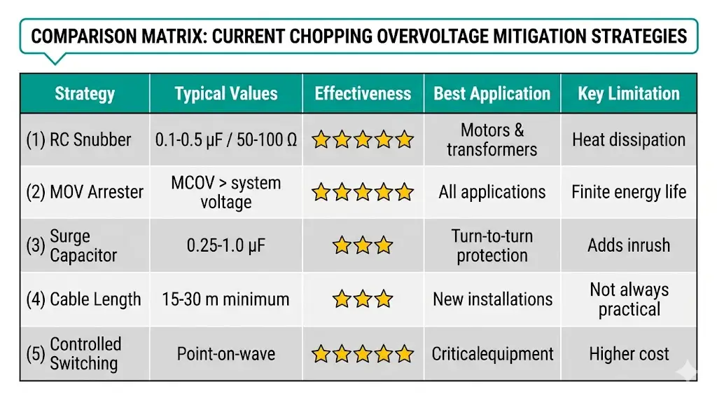
Effective protection against current chopping overvoltages combines surge suppression at load terminals with appropriate switchgear selection. Field testing across mining and petrochemical facilities demonstrates that combined approaches reduce transients from 6+ per unit to below 2 per unit.
Strategy 1: RC Surge Suppressors (Snubbers)
RC snubbers increase effective circuit capacitance while adding resistive damping. For medium-voltage motor protection:
Snubbers installed at load terminals reduce overvoltages 25% more effectively than those mounted at switchgear compartments. Keep lead lengths below 1.5 m to maintain high-frequency response.
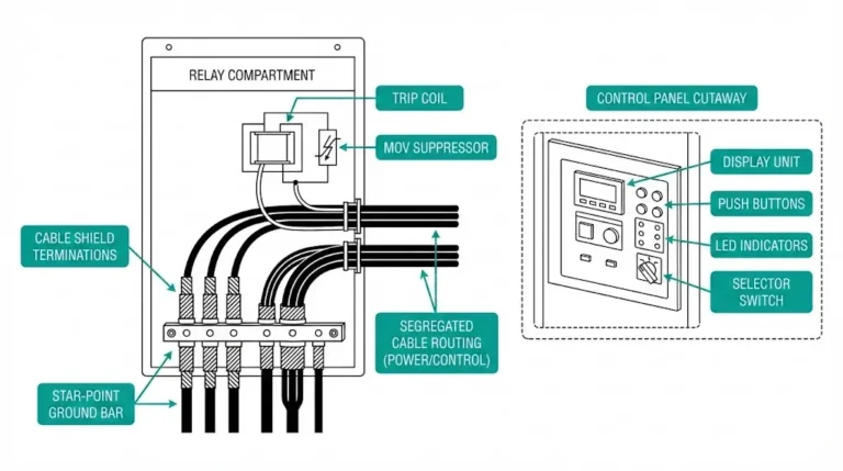
Strategy 2: Metal Oxide Varistors (MOV)
MOV arresters clamp voltage at a defined protection level regardless of oscillation magnitude. Selection criteria:
According to IEEE C62.22, coordination between arrester protective level and equipment insulation must maintain adequate margin throughout expected service conditions.
Strategy 3: Surge Capacitors
Dedicated surge capacitors (0.25–1.0 µF) slow the rate of voltage rise, protecting turn-to-turn insulation that cannot withstand steep wavefronts. Often paired with damping resistors to prevent oscillation.
Strategy 4: Cable Length Optimization
Cable capacitance—approximately 250–300 pF/m for typical medium-voltage cable—naturally increases system capacitance. Minimum recommended lengths:
This passive approach uses existing infrastructure but may not be practical for all installations.
Strategy 5: Controlled Switching (Point-on-Wave)
Synchronizing contact operation to optimal phase angle addresses the root cause. Opening contacts when current naturally approaches zero minimizes chopping magnitude. Reserved for critical high-value equipment (large reactors, critical transformer banks) due to higher cost.
Proper switchgear selection prevents overvoltage problems before they occur. Key considerations for applications involving small inductive loads:
Vacuum contactor vs. circuit breaker: Contactors optimized for frequent operations (up to 10⁶ mechanical cycles) often feature contact materials specifically selected for motor switching duty. Lower chopping current variants may be available.
Specifications to request:
When SF₆ alternatives warrant consideration: Shunt reactors at transmission voltage levels and applications where even mitigated vacuum transients pose unacceptable risk may justify SF₆ switchgear despite higher cost and environmental considerations.
| Application | Recommended Switchgear | Recommended Protection |
|---|---|---|
| Small motors (<500 kW), frequent switching | Vacuum contactor | RC snubber at motor terminals |
| Large motors (>500 kW), infrequent switching | Vacuum circuit breaker | Surge arrester + surge capacitor |
| Dry-type transformers | Vacuum circuit breaker | RC snubber at transformer terminals |
| Shunt reactors | VCB with controlled switching or SF₆ | MOV arrester + controlled switching |
A comprehensive VCB specification checklist helps ensure all critical parameters are addressed during procurement.
XBRELE’s engineering team provides application-specific analysis for installations involving small inductive loads. Our technical support includes:
Contact our engineers to discuss your specific application requirements and develop a coordinated protection strategy.
What exactly causes current chopping in vacuum circuit breakers?
Current chopping results from arc instability when current falls below approximately 3–8 A in vacuum interrupters. At these low current levels, insufficient metal vapor evaporates from contact surfaces to sustain the arc plasma, causing premature extinction before the natural current zero crossing.
Why do motors under 100 kW experience worse switching transients than larger motors?
Smaller motors have high winding inductance relative to very low stray capacitance, creating surge impedance values that can exceed 10,000 Ω. The overvoltage equation V = Ic × √(L/C) produces dangerous peaks when this L/C ratio is large, while bigger motors benefit from higher inherent capacitance that dampens transients.
What RC snubber values should I use for medium-voltage motor protection?
Standard industrial practice for 3.6–12 kV systems employs capacitance of 0.1–0.5 µF paired with resistance of 50–100 Ω, installed directly at motor terminals rather than at the switchgear compartment for optimal high-frequency suppression.
How can I tell if equipment damage resulted from switching transients versus other causes?
Switching transient damage typically shows inter-turn insulation failures concentrated near terminal-end windings, with failures occurring shortly after de-energization events. Thermal degradation, by contrast, produces more distributed damage patterns and correlates with continuous operation rather than switching events.
Should I specify SF₆ instead of vacuum for small transformer switching?
For most distribution applications below 36 kV, properly protected vacuum switchgear performs adequately. SF₆ may be justified for critical shunt reactor applications or when switching very small dry-type transformers (<100 kVA) with extremely high switching frequency where even mitigated vacuum transients accumulate unacceptable stress.
How does contact wear affect chopping current over the interrupter’s service life?
Eroded contact surfaces may exhibit modestly higher chopping current due to altered surface characteristics affecting vapor release. This can partially explain overvoltage problems appearing on equipment that operated successfully for years, particularly in high-switching-frequency applications.
What is the difference between current chopping and virtual current chopping?
Conventional current chopping affects one phase at low current due to arc instability. Virtual current chopping creates artificial high-frequency current zeros in multiple phases simultaneously through capacitive coupling when a first-phase arc re-ignites—this can occur even at higher load currents and represents a distinct phenomenon requiring additional mitigation consideration.