Benötigen Sie die vollständigen Spezifikationen?
Laden Sie unseren Produktkatalog 2025 herunter, um detaillierte Zeichnungen und technische Parameter aller Schaltanlagenkomponenten zu erhalten.
Katalog anfordernLaden Sie unseren Produktkatalog 2025 herunter, um detaillierte Zeichnungen und technische Parameter aller Schaltanlagenkomponenten zu erhalten.
Katalog anfordernLaden Sie unseren Produktkatalog 2025 herunter, um detaillierte Zeichnungen und technische Parameter aller Schaltanlagenkomponenten zu erhalten.
Katalog anfordern
Ein 12-kV-Vakuum-Leistungsschalter wurde in einem Zementwerk in den Anden in 2.800 Metern Höhe installiert. Sechs Monate später versagte er bei einem Routineschaltvorgang - nicht wegen eines Herstellungsfehlers, sondern wegen eines Überschlags auf der Isolationsoberfläche, die bei den Werkstests auf Meereshöhe einwandfrei funktioniert hatte.
Die Ursache: ein unzureichender Basisimpulspegel für die kombinierte Belastung durch Höhenluft und Zementstaub. Der standardmäßige 75 kV BIL, der in 1.000 Metern Höhe in sauberer Luft ausreicht, konnte transienten Überspannungen nicht standhalten, als die Luftdichte auf 30% abfiel und die Verschmutzung jede exponierte Oberfläche bedeckte.
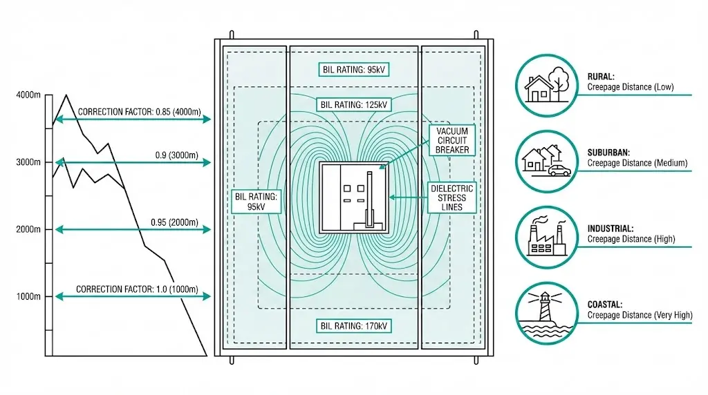
Die Isolationskoordination verhindert genau diesen Ausfallmodus. Sie passt die dielektrische Festigkeit der Ausrüstung an die tatsächliche Spannungsbelastung an - sie berücksichtigt, wo die Ausrüstung betrieben wird, und nicht nur, welche Spannung sie führt. BIL quantifiziert die Widerstandsfähigkeit gegen transiente Überspannungen, ausgedrückt als Spitzenkilovolt für eine standardisierte Blitzimpulswellenform.
Bei der Auswahl von Mittelspannungs-BILs sind drei Faktoren ausschlaggebend: die Höhe (Verringerung der Luftdichte), der Grad der Verschmutzung (Oberflächenverunreinigung) und die Eigenschaften des Kabelsystems (Anpassung des Wellenwiderstands). Dieser Leitfaden bietet praktische Auswahlmethoden für jeden dieser Faktoren, mit IEC-basierten Berechnungen und Entscheidungstabellen, die Ingenieure direkt auf Beschaffungsspezifikationen anwenden können.
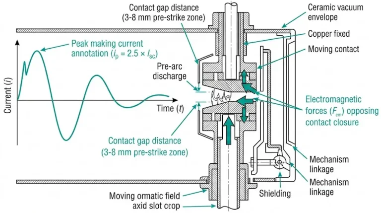
Für ein grundlegendes Verständnis von Funktionsprinzipien von Vakuum-Leistungsschaltern, Die verlinkte Ressource befasst sich mit Lichtbogenlöschmechanismen und Kontaktdesign, die die Isolationsanforderungen beeinflussen.
Der Basisimpulspegel definiert die Spitzenspannung, der elektrische Geräte bei transienten Überspannungsereignissen, insbesondere bei Blitzeinschlägen und Schaltüberspannungen, standhalten müssen. Für Mittelspannungsanlagen zwischen 3,6 kV und 36 kV liegen die BIL-Werte typischerweise zwischen 40 kV und 170 kV, was einem Verhältnis von 5:1 bis 6:1 zwischen Impulsfestigkeit und Nennbetriebsspannung entspricht.
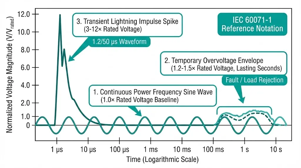
Die Physik konzentriert sich auf das Verhältnis von Spannung und Zeit bei Impulsereignissen. Ein Standard-Blitzimpuls erreicht in 1,2 Mikrosekunden seinen Spitzenwert und fällt in 50 Mikrosekunden auf 50% ab (die in IEC 60060-1 definierte Wellenform 1,2/50 μs). Diese schnelle Spannungsspitze belastet die Isolierung anders als eine kontinuierliche Netzfrequenzspannung.
Drei Spannungskategorien erfordern eine Koordinierung:
| Stress-Typ | Dauer | Typische Größenordnung | Quelle |
|---|---|---|---|
| Netzfrequenz | Kontinuierlich | 1,0 × Nennspannung | Normaler Betrieb |
| Vorübergehende Überspannung | Sekunden bis Minuten | 1,2-1,5 × Nennspannung | Störungsbeseitigung, Lastabfuhr |
| Transiente Überspannung | Mikrosekunden | 3-12 × Nennspannung | Blitzschlag, Schaltung |
Gemäß IEC 60071-1 (Isolationskoordination - Teil 1: Definitionen, Grundsätze und Regeln) folgen die Standard-BIL-Werte einer bevorzugten Reihe. Für Systeme mit Um = 36 kV beträgt der Standard-BIL 170 kV, während für Systeme mit Um = 12 kV typischerweise BIL-Werte von 75 kV oder 95 kV erforderlich sind, abhängig von der Konfiguration der neutralen Erdung und der erwarteten Stärke der Überspannung.
Die dielektrische Widerstandsfähigkeit hängt von drei miteinander verbundenen Faktoren ab: der Durchschlagsfestigkeit des Isoliermaterials (typischerweise 20-40 kV/mm für XLPE-Kabel), der geometrischen Konfiguration, die die Verteilung des elektrischen Feldes bestimmt, und den Umgebungsbedingungen einschließlich des atmosphärischen Drucks.
Standard-BIL-Werte für Mittelspannungsgeräte:
| Nennspannung (kV) | Standard-BIL-Optionen (kV Spitze) |
|---|---|
| 3.6 | 20, 40 |
| 7.2 | 40, 60 |
| 12 | 60, 75, 95 |
| 17.5 | 75, 95 |
| 24 | 95, 125, 145 |
| 36 | 145, 170 |
Die Auswahl zwischen den Optionen hängt von der Erdungsmethode des Systems, der Häufigkeit der Blitzeinwirkung und - was besonders wichtig ist - von den Umgebungsfaktoren ab, die die effektive Durchschlagsfestigkeit verringern.
Die Luftdichte nimmt mit der Höhe ab, wodurch sich die Durchschlagfestigkeit proportional verringert. Auf Meereshöhe (1.013 hPa) bietet Standardluft eine grundlegende Isolationskapazität. Mit zunehmender Höhe breiten sich die Moleküle weiter aus, und die Durchschlagsspannung sinkt. Geräte, die auf Meereshöhe für 75 kV BIL ausgelegt sind, können in 3.000 Metern Höhe ohne Korrektur nur noch 60 kV BIL liefern.
Die Korrektur wird oberhalb von 1.000 Metern gemäß IEC 60071-2 obligatorisch. Die Formel:
K_a = e^(H/8150)
Dabei entspricht K_a dem Höhenkorrekturfaktor und H der Höhe in Metern.
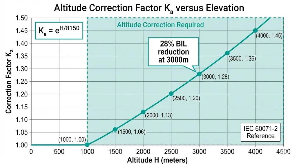
Vorberechnete Höhenkorrekturfaktoren:
| Höhenlage (m) | Korrekturfaktor K_a | Effektive BIL-Reduzierung |
|---|---|---|
| 1,000 | 1,00 (Referenz) | 0% |
| 1,500 | 1.06 | 6% |
| 2,000 | 1.13 | 13% |
| 2,500 | 1.20 | 20% |
| 3,000 | 1.28 | 28% |
| 3,500 | 1.36 | 36% |
| 4,000 | 1.45 | 45% |
Praktische Anwendung: Eine 12-kV-VCB, die für einen Standort von 2 500 m bestimmt ist, erfordert eine BIL von mindestens 75 × 1,20 = 90 kV. Wählen Sie den nächsten Standardwert: 95 kV BIL.
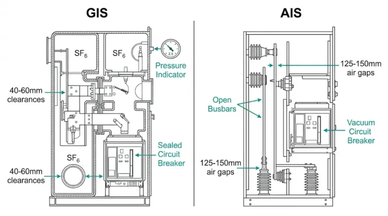
Für die Höhenkompensation gibt es zwei Möglichkeiten der Umsetzung. Erstens: Spezifizieren Sie Geräte der höheren BIL-Klasse - 95 kV anstelle von 75 kV für die gleiche Nennspannung. Zweitens, verlangen Sie erweiterte Kriech- und Luftstrecken, die proportional erhöht werden. Die meisten Hersteller von Vakuum-Leistungsschaltern bieten höhenabhängige Varianten an. Geben Sie die Einbauhöhe in den Ausschreibungsunterlagen an - eine Nachrüstung kostet weit mehr als eine korrekte Erstspezifikation.
[Experteneinblick: Höhenauswahl]
- Standorte über 2.000 m sollten unabhängig von den Berechnungsergebnissen standardmäßig der nächsthöheren BIL-Klasse zugeordnet werden
- In trockenen Umgebungen mit geringer Luftfeuchtigkeit und in großen Höhen erholt sich die Spannung nach Teilentladungen schneller
- Kombinierte Höhen- und Verschmutzungseffekte verstärken sich - wenden Sie beide Korrekturen nacheinander an
- Anforderung von Höhenprüfzertifikaten des Herstellers für Anlagen über 3.000 m
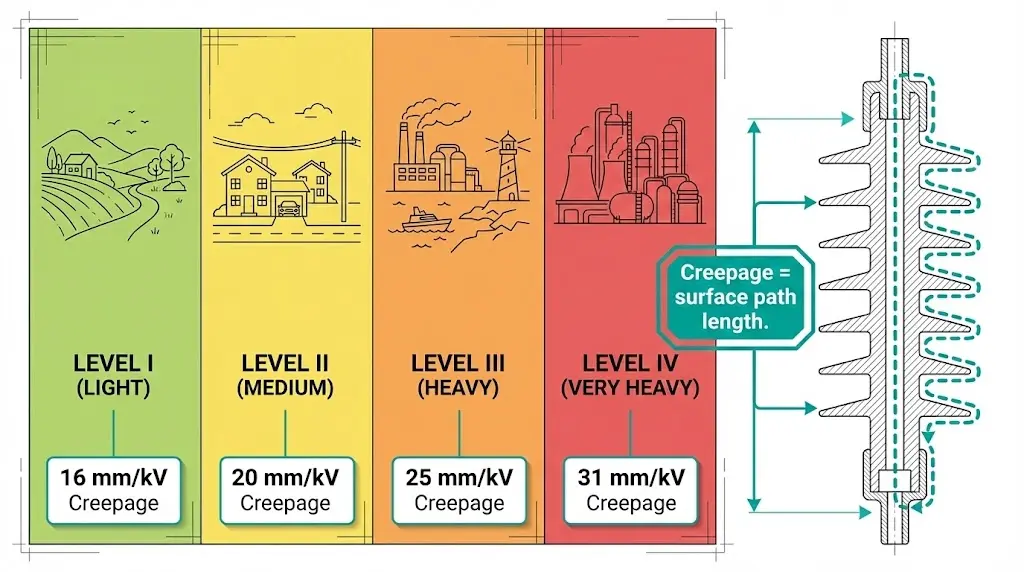
Oberflächenverunreinigungen - Salzsprühnebel, Zementstaub, Industriepartikel, Chemikalien in der Landwirtschaft - bilden in Verbindung mit Feuchtigkeit leitfähige Pfade. Die IEC 60815 definiert vier Verschmutzungsgrade auf der Grundlage der Umweltexposition:
| Verschmutzungsgrad | Beschreibung | Typische Umgebungen |
|---|---|---|
| I - Licht | Minimale industrielle Verschmutzung, kein Salz | Ländliche Gebiete, geringe Verkehrsdichte |
| II - Mittel | Mäßige Belastung durch Industrie oder Verkehr | Vorstädtische Gebiete, Leichtindustrie |
| III - Schwer | Starke industrielle Aktivität, Küstengebiet 1-10 km | Schwerindustrie, in Küstennähe |
| IV - Sehr schwer | Leitfähiger Staub, direktes Salzspray, Chemikalien | Zementwerke, Küstenanlagen, chemische Verarbeitung |
Die Kriechstrecke - die Länge des Oberflächenweges zwischen stromführenden Teilen und dem Boden - muss mit der Schwere der Verschmutzung zunehmen:
| Verschmutzungsgrad | Mindestkriechstrecke (mm/kV) |
|---|---|
| I - Licht | 16 |
| II - Mittel | 20 |
| III - Schwer | 25 |
| IV - Sehr schwer | 31 |
Berechnungsbeispiel: 12-kV-Geräte in Umgebungen der Stufe III erfordern eine Mindestkriechstrecke von (12 ÷ √3) × 25 = 173 mm.
Innenraumgeräte in ordnungsgemäß abgedichteten, klimatisierten Schaltanlagenräumen erfüllen in der Regel die Verschmutzungsstufe I oder II. Die Erfahrung in der Praxis zeigt jedoch, dass sich in schlecht belüfteten Innenräumen - insbesondere in Bergbau- und Zementbetrieben - im Laufe von 5-10 Jahren Verunreinigungen ansammeln, die an der Oberfläche Spuren hinterlassen. Beurteilen Sie die tatsächliche Luftqualität, anstatt davon auszugehen, dass Innenräume automatisch sauber sind.
Für VCB-Auswahl für den Außenbereich versus Innenbereich, Die Bestimmung des Verschmutzungsgrads wirkt sich sowohl auf die Anschaffungskosten als auch auf die langfristige Zuverlässigkeit der Geräte aus.
Hochgelegene Standorte fallen häufig mit starker Umweltverschmutzung zusammen - Bergbau in 3.500 m Höhe, Zementwerke in Bergtälern, abgelegene Industrieanlagen fernab der Netzinfrastruktur. Beide Faktoren wirken sich negativ aus.
Sequentielle Anwendungsmethode:
Bearbeitetes Beispiel: 24 kV-VCB im Freien in 3.500 m Höhe in einem Zementwerk (Verschmutzungsgrad IV):
Kombinierte Auswahlentscheidungsmatrix:
| Zustand des Standorts | Empfohlene Maßnahme |
|---|---|
| ≤1.000 m, Verschmutzung I-II | Standard-BIL, Standard-Kriechgang |
| 1.000-2.000 m, Verschmutzung I-II | Nächsthöhere BIL-Klasse |
| >2.000 m, jegliche Verschmutzung | Genaues K_a berechnen, höhenfeste Ausrüstung angeben |
| Verschmutzung III-IV, jede Höhe | Erweiterte Kriechstromisolatoren, Silikongehäuse in Betracht ziehen |
| Kombination aus großer Höhe und starker Verschmutzung | Beide Korrekturen angewendet, Rücksprache mit dem Hersteller erforderlich |
Isoliergehäuse aus Silikongummi übertreffen Porzellan in Umgebungen der Stufen III und IV aufgrund ihrer hydrophoben Oberflächeneigenschaften, die Wasser abperlen lassen, anstatt leitende Filme zu bilden.
[Experteneinblick: Einsatz in rauer Umgebung]
- Feldversagensdaten zeigen, dass kombinierte Höhenverschmutzungseffekte für 60%+ der Isolationsversagen über 2.000 m verantwortlich sind
- Silikongehäuse behalten ihre Hydrophobie für 15-20 Jahre; Porzellan muss regelmäßig gereinigt werden
- Geben Sie den Verschmutzungsgrad in den Beschaffungsunterlagen an - die Hersteller können die Bedingungen vor Ort nicht erraten.
- Regelmäßige Isolationswiderstandsprüfungen (mindestens einmal jährlich), um eine Verschlechterung vor dem Ausfall zu erkennen
Energiekabel stellen andere Anforderungen an die Isolationskoordination als luftisolierte Geräte. XLPE- und EPR-Kabel haben eine höhere Dielektrizitätskonstante (ε_r ≈ 2,3-3,5), eine geringere Stoßimpedanz (20-50 Ω gegenüber 300-400 Ω bei Freileitungen) und eine minimale BIL-Marge über die Nennwerte hinaus.
Standard Kabel BIL Werte:
| Kabel Nennspannung U₀/U (kV) | BIL (kV Spitze) |
|---|---|
| 3.6/6 | 60 |
| 6/10 | 75 |
| 8.7/15 | 95 |
| 12/20 | 125 |
| 18/30 | 170 |
Wenn Wanderwellen auf eine Impedanzdiskontinuität treffen - Übergang zwischen Kabel und Freileitung, offener Kabelabschluss - kommt es zur Spannungsreflexion. An einem offenen Ende kann sich die Spannung theoretisch verdoppeln. Kabelendverschlüsse und Schaltanlagen, die an Kabel angeschlossen sind, sind höheren transienten Belastungen ausgesetzt als Geräte in reinen Freileitungssystemen.

Schutzstrategien:
Kurze Kabelstrecken (200 m) erfordern eine Analyse der verteilten Parameter für die Überspannungskoordination. Bei unterirdischen Verteilungsnetzen mit gemischten Kabel- und Freileitungsabschnitten sollten Überspannungsableiter an jeder Kabelverzweigung angebracht werden.
Das VCB-RFQ-Checkliste enthält Anforderungen an die Kabelkoordinierung, die von den Beschaffungsspezialisten vor der endgültigen Festlegung der Spezifikationen überprüft werden sollten.
Schritt 1: Bestimmen der Systemspannungsklasse
Identifizieren Sie die maximale Systemspannung (U_m) gemäß den lokalen Netzstandards und den Standort der Geräte innerhalb des Netzes.
Schritt 2: Basis-BIL auswählen
Wählen Sie die Standard-BIL aus den Tabellen der IEC 60071-1 für die jeweilige Spannungsklasse. Effektiv geerdete Systeme erlauben eine niedrigere BIL; nicht geerdete oder widerstandsgeerdete Systeme erfordern höhere Werte.
Schritt 3: Berechnung der Höhenkorrektur
Wenden Sie K_a = e^(H/8150) für Anlagen über 1.000 m an. Runden Sie auf den nächsten Standard-BIL-Wert auf.
Schritt 4: Bestimmung des Verschmutzungsgrads
Bewertung der Standortumgebung anhand der Kriterien der IEC 60815. Wenn Sie unsicher sind, wählen Sie eine Stufe höher als die erste Bewertung.
Schritt 5: Berechnung der Mindestkriechstrecke
Multiplizieren Sie die Phase-Erde-Spannung mit dem Kriechfaktor für den Verschmutzungsgrad.
Schritt 6: Abbildung der Ausrüstungskoordinationskette
Überprüfen Sie die BIL-Werte für: Transformator (höchste) → Schaltanlage (mittlere) → Kabel (durch Ableiter geschützt) → Überspannungsableiter (Schutzniveau unter der BIL aller Geräte).
Schritt 7: Festlegen der Überspannungsableiter-Schutzstufen
Die Restspannung des Ableiters muss bei maximalem Entladestrom 15-20% unter der BIL des geschützten Geräts bleiben.
Schritt 8: Vollständige Spezifikationen dokumentieren
Geben Sie in den Beschaffungsunterlagen die Höhe, den Verschmutzungsgrad, die erforderliche BIL, die Kriechstrecke und die Ableiterkoordination an.
Die Schutzmarge wird wie folgt berechnet: Marge (%) = [(BILAusrüstung - VSchutzniveau) ÷ VSchutzniveau] × 100. Für den Blitzschutz empfiehlt die IEC 60071-2 eine Mindestspanne von 15-25%, abhängig von der Kritikalität der Anlage und den Höhenkorrekturfaktoren.
Fehlermuster 1: Unterschätzung der Flughöhe
Geräte, die für die Leistung auf Meereshöhe spezifiziert sind, versagen in hochgelegenen Minen oder Gebirgsanlagen. Die BIL-Reduzierung des 28% in 3.000 m Höhe übertrifft die Standardauslegungsmargen. Schaltüberschläge treten im Normalbetrieb auf, nicht nur im Fehlerfall.
Prävention: Dokumentieren Sie immer die Installationshöhe in den Beschaffungsspezifikationen. Fordern Sie Geräte mit Höheneinstufung oder der nächsthöheren BIL-Klasse an.
Versagensmuster 2: Kriechende Verschmutzung
Reinraum-Annahmen für Innenraum-Schaltanlagen ignorieren die Realität der Belüftung. Die Staubinfiltration über 5-10 Jahre hinweg führt zu oberflächlichen Kriechspuren, die nach längeren Regen- oder Feuchtigkeitsereignissen plötzlich auftreten.
Prävention: Jährliche Prüfung des Isolationswiderstands. Aufstellung von Reinigungsplänen für staubige Umgebungen. Ziehen Sie versiegelte Schaltanlagen für Level III+ Standorte in Betracht.
Fehlermuster 3: Vernachlässigung des Kabelabschlusses
Überspannungsableiter sind an den Transformatorenklemmen installiert, fehlen aber an den Kabel-Schaltanlagen-Verbindungen. Der Kabelabschluss - die schwächste Isolationsverbindung - versagt eher bei Schalttransienten als bei Blitzeinschlägen.
Prävention: Installieren Sie Überspannungsableiter an jedem Kabelanschluss. Vergewissern Sie sich, dass die Energieleistung des Ableiters der erwarteten Überspannungsleistung entspricht.
Checkliste für die Überprüfung der Inbetriebnahme:
Eine ordnungsgemäße Koordinierung der Isolierung setzt die Umweltbedingungen in Gerätespezifikationen um. Eine BIL-Auswahl ohne Höhenkorrektur garantiert einen eventuellen Ausfall in der Höhe. Das Ignorieren des Verschmutzungsgrades führt zu Oberflächenverfolgung und Überschlägen. Die Vernachlässigung der Impedanzcharakteristik von Kabeln macht die Endverschlüsse anfällig.
Kritische Spezifikationselemente für Beschaffungsdokumente:
Normen zum Nachschlagen: IEC 60071-1/2 (Isolationskoordination), IEC 60815 (Verschmutzungsklassifizierung), IEC 62271-1 (Hochspannungsschaltanlagen), IEEE C62.82.1 (nordamerikanische Anwendungen).
Bei schwierigen Standorten ist die Beratung durch den Hersteller wichtig. Kundenspezifische Höhenangaben, erweiterte Kriechoptionen und Silikongehäuse-Upgrades erfordern anwendungstechnische Unterstützung, die über das Standardkatalogangebot hinausgeht.
XBRELE bietet höhengeprüfte Vakuum-Leistungsschalter, die bis zu einer Höhe von 4.000 m getestet wurden, verschmutzungsresistente Konstruktionen mit Silikongehäusen für Umgebungen der Stufe IV sowie technische Unterstützung bei komplexen Anforderungen an die Isolationskoordination. Wenden Sie sich an unser Ingenieurteam, um die Isolationskoordination für Ihr nächstes Mittelspannungsprojekt zu prüfen.
Externe Referenz: IEC 60071 Isolationskoordination Norm Seite - Technische Veröffentlichung der Internationalen Elektrotechnischen Kommission zur Koordinierung der Isolierung.
F: Was ist der Unterschied zwischen BIL und Netzfrequenz-Stehspannung?
A: BIL misst die Widerstandsfähigkeit gegen schnelle Überspannungen im Mikrosekundenbereich, während die Netzfrequenzbeständigkeit eine Minute lang eine anhaltende Spannungsbelastung bei 50/60 Hz testet - die Geräte müssen beide Tests bestehen, da beide unterschiedliche Mechanismen des Isolationsversagens bewerten.
F: Ab welcher Höhe ist ein Isolationsderating vorgeschrieben?
A: Die IEC-Normen erfordern eine Höhenkorrektur oberhalb von 1.000 m; bei 2.000 m erreicht der Korrekturfaktor 1,13, was bedeutet, dass die Geräte einen um etwa 13% höheren BIL-Wert als auf Meereshöhe benötigen, um einen gleichwertigen Schutz zu gewährleisten.
F: Können Schaltanlagen für Innenräume die Anforderungen an den Verschmutzungsgrad ignorieren?
A: Nicht zuverlässig - schlecht belüftete Innenräume, vor allem in Industrieanlagen, die mit Pulvern umgehen oder in Küstennähe liegen, können über Jahre hinweg Verunreinigungen ansammeln, die bei hoher Luftfeuchtigkeit Kriechwege bilden.
F: Wie bestimme ich den richtigen Verschmutzungsgrad für meinen Aufstellungsort?
A: Bewerten Sie die Nähe zu Verschmutzungsquellen (Entfernung zur Küste, Industrieemissionen, landwirtschaftliche Aktivitäten), lokale Klimamuster (Luftfeuchtigkeit, Niederschlagshäufigkeit) und historische Verschmutzungsdaten von nahe gelegenen Anlagen; wenn die Bewertung unsicher ist, wählen Sie eine Stufe höher als die erste Schätzung.
F: Warum fallen Kabelendverschlüsse häufiger aus als andere Isolationspunkte?
A: Kabelendverschlüsse erfahren eine Spannungsverdopplung durch Überspannungsreflexion bei Impedanzfehlern zwischen Kabel (20-50 Ω) und angeschlossenen Geräten (300+ Ω), was sie zum schwächsten koordinierten Glied macht, wenn sie nicht durch entsprechend bemessene Überspannungsableiter geschützt sind.
F: Sollte ich für hochgelegene Standorte höhengeprüfte Geräte spezifizieren oder eine erweiterte Kriechstrecke verwenden?
A: Geräte mit Höheneinstufung und höherer BIL-Klasse werden in der Regel oberhalb von 2.000 m bevorzugt, da sie sowohl die innere als auch die äußere Isolierung gleichzeitig berücksichtigen.
F: Wie oft sollte der Isolationswiderstand in rauen Umgebungen geprüft werden?
A: Jährliche Prüfungen stellen die Mindestpraxis für Umgebungen der Verschmutzungsstufen III und IV dar, wobei vierteljährliche Prüfungen für Zementwerke, Küstenanlagen und andere Orte empfohlen werden, an denen sich die Verschmutzung zwischen den Reinigungszyklen schnell ansammelt.