Need Full Specifications?
Download our 2025 Product Catalog for detailed drawings and technical parameters of all switchgear components.
Get CatalogDownload our 2025 Product Catalog for detailed drawings and technical parameters of all switchgear components.
Get CatalogDownload our 2025 Product Catalog for detailed drawings and technical parameters of all switchgear components.
Get Catalog
Power factor correction capacitors without properly sized detuning reactors create resonant circuits that amplify harmonic currents, leading to premature failures, nuisance fuse operations, and equipment damage. This guide delivers practical sizing methods, resonance verification procedures, and field-proven troubleshooting techniques for industrial capacitor bank installations.
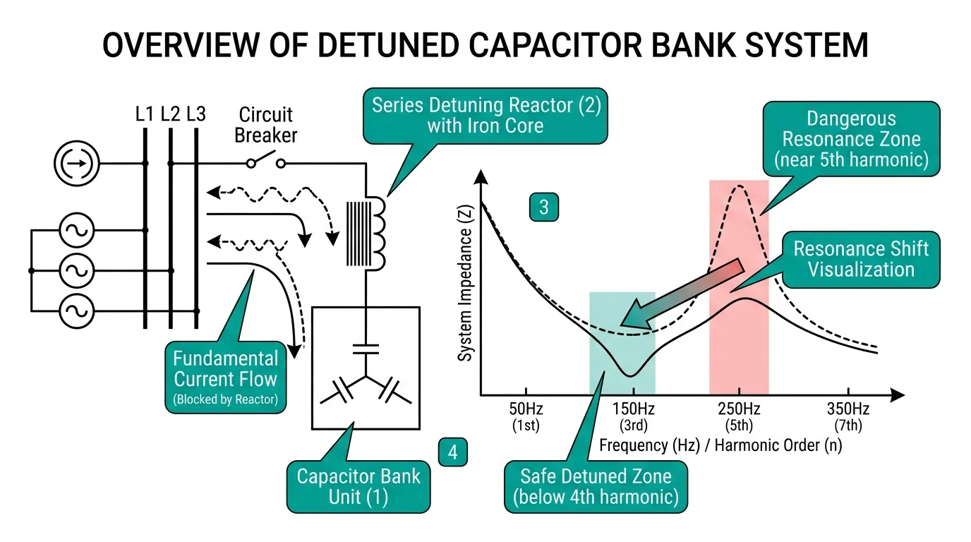
Detuning reactor sizing begins with understanding the harmonic resonance risks inherent in power factor correction systems. When capacitor banks connect to industrial networks without proper detuning, the system’s natural resonant frequency often aligns with dominant harmonic orders—creating dangerous current amplification that damages equipment and trips protective devices.
Field assessments across 40+ industrial facilities with power quality issues reveal a consistent pattern: failed capacitor installations share a common root cause of mismatched detuning reactor impedance relative to the facility’s actual harmonic spectrum. The detuning factor—expressed as a percentage (p%)—determines the tuned frequency of the reactor-capacitor combination.
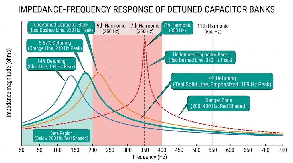
The resonant frequency of an LC circuit follows: fr = 1 / (2π√LC), where L is the reactor inductance in henries and C is the capacitor bank capacitance in farads. For a 7% detuning reactor paired with a 400 V, 50 kvar capacitor bank, the tuned frequency drops to approximately 189 Hz—safely below the 5th harmonic (250 Hz) that dominates most industrial loads.
According to IEC 61642 (Industrial AC Networks Affected by Harmonics), capacitor banks in harmonic-rich environments require detuning reactors sized to shift the resonant point below the lowest significant harmonic order. Standard detuning factors include 5.67%, 7%, and 14%, each targeting specific harmonic mitigation strategies.
The physics governing detuning effectiveness relies on impedance magnitude at harmonic frequencies. A properly detuned system presents inductive impedance at all frequencies above the tuned point, preventing capacitive amplification. Field measurements show that 7% detuning typically reduces 5th harmonic current amplification from factors of 3–5× down to less than 1.2×—effectively eliminating resonance-induced failures.
Reactor thermal rating must accommodate harmonic current superposition. A detuning reactor in typical variable frequency drive environments carries fundamental current plus harmonic components totaling 120–140% of nominal capacitor current, requiring Class H insulation (180°C rating) for reliable long-term operation.
[Expert Insight: Detuning Factor Selection]
- Default to 7% detuning for general industrial applications with VFD loads below 40% of total connected load
- Select 14% detuning when LED lighting or single-phase rectifier loads exceed 25% of facility demand
- Avoid 5.67% detuning unless harmonic surveys confirm 5th harmonic voltage distortion below 3%
- Always verify short-circuit capacity variations between peak and minimum load conditions
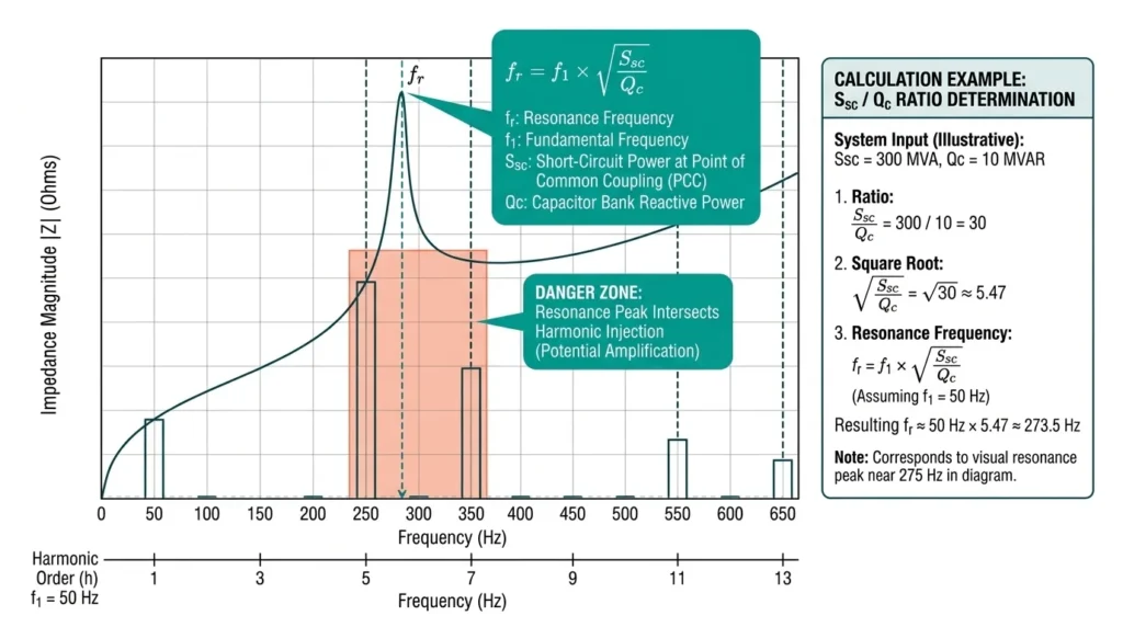
Pre-installation resonance analysis prevents equipment failures that would otherwise cost €50,000–200,000 in replacement components and production downtime. The fundamental resonance condition occurs when system inductive reactance equals capacitive reactance at a specific harmonic frequency.
Without detuning reactors, standard capacitor banks typically resonate between the 5th and 13th harmonic orders—precisely where variable frequency drives, LED lighting, and switched-mode power supplies inject significant harmonic currents.
The resonant frequency calculation follows: fr = f1 × √(Ssc/Qc), where f1 = fundamental frequency (50 Hz), Ssc = short-circuit power at the point of common coupling (MVA), and Qc = capacitor bank reactive power (Mvar). Systems with Ssc/Qc ratios between 25 and 169 create resonance points at the 5th through 13th harmonics.
According to IEC 61642, harmonic voltage distortion at capacitor terminals must not exceed 1.3 times the supply harmonic voltage. Field measurements in steel rolling mills showed amplification factors reaching 8–12× at resonant frequencies without detuning protection.
Three critical parameters require verification during resonance assessment:
Harmonic current spectrum analysis using power quality analyzers per IEC 61000-4-7 identifies dominant harmonic orders requiring attention.
Practical troubleshooting begins with impedance scanning—either through simulation software or field measurements—to map the frequency-dependent impedance characteristic before selecting detuning reactor tuning factors.
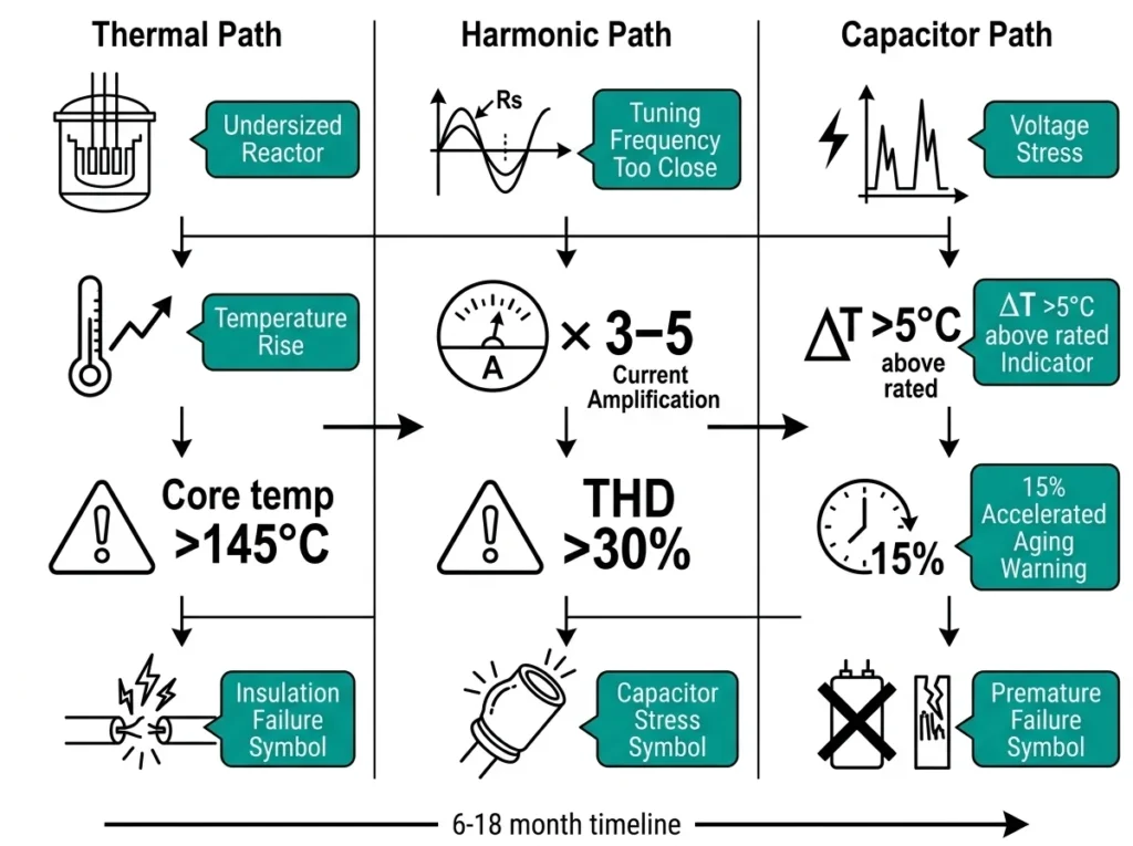
Mismatched detuning factors cause three primary failure categories: thermal runaway, harmonic amplification, and premature component degradation. Recognizing these failure mechanisms enables targeted troubleshooting before catastrophic equipment loss occurs.
When detuning reactors are undersized relative to harmonic content, thermal stress accelerates exponentially. Reactors rated for 7% detuning in systems with dominant 5th harmonic current experience circulating currents exceeding design limits.
At a steel rolling mill installation, reactor core temperatures reached 145°C within 18 months of commissioning. The root cause: specifying 7% detuning without verifying that system impedance shifted the effective resonant point closer to the 5th harmonic during light-load conditions.
Selecting a detuning factor too close to a dominant harmonic order creates amplification rather than attenuation. According to IEEE 519-2022, systems should maintain separation of at least 10% between the tuning frequency and any significant harmonic order.
When this margin is violated, capacitor banks absorb amplified harmonic currents, causing dielectric heating and accelerated aging. Capacitor failure rates increase by approximately 15% for every 5°C rise above the rated 40°C ambient operating temperature.
Critical Frequency Relationship: The detuning factor p relates to resonant frequency fr by: fr = f1 / √p, where f1 = 50 Hz (or 60 Hz). A 7% reactor yields fr ≈ 189 Hz, safely below the 5th harmonic at 250 Hz.
During troubleshooting, measure reactor surface temperature with infrared thermography—sustained readings above 85°C indicate potential sizing mismatch. Monitor capacitor bank current for harmonic distortion exceeding 30% THD, which suggests inadequate detuning margin. Audible humming at frequencies corresponding to nearby harmonics confirms resonance proximity requiring immediate engineering review.
[Expert Insight: Warning Signs of Imminent Failure]
- Fuse operations occurring within 30 minutes of capacitor bank energization suggest inrush-related resonance
- Progressive fuse failures over 3–6 months indicate thermal degradation from harmonic overload
- Capacitor can bulging or oil leakage signals advanced dielectric breakdown requiring immediate de-energization
- Reactor humming that varies with time of day correlates with load-dependent resonance shifting
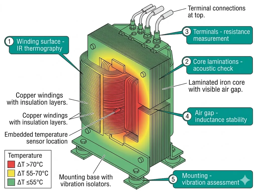
Even correctly sized reactors require systematic health assessment. Reactor degradation often precedes capacitor failures by 6–12 months—making proactive inspection essential for maintenance programs.
Begin with visual assessment of reactor winding integrity. Discoloration patterns on winding surfaces indicate localized overheating. According to IEEE C57.16 (Reactors for Power Systems), reactor insulation begins degrading when hotspot temperatures exceed 120°C for Class B insulation systems.
During thermal imaging surveys, healthy iron-core detuning reactors operate with hotspot temperatures 40–55°C above ambient under rated load conditions.
Key thermal thresholds for reactor assessment:
Inductance drift indicates core saturation problems or winding damage. Measure reactor inductance using an LCR meter at rated frequency and compare against nameplate values. Per IEC 60076-6 (Reactors), measured inductance should remain within ±5% of rated value under normal conditions. Deviations exceeding this tolerance signal core material degradation or air gap changes in gapped iron-core designs.
Listen for abnormal acoustic signatures during energization. Healthy detuning reactors produce consistent 100 Hz (50 Hz systems) or 120 Hz (60 Hz systems) hum from magnetostriction. Irregular buzzing, rattling, or intermittent noise patterns suggest loose laminations or mounting hardware—common precursors to resonance amplification failures.
Reactor performance degradation manifests subtly before catastrophic failure occurs. Harmonic current measurements provide the most reliable early warning indicators. Effective reactor evaluation requires systematic measurement protocols that identify tuning drift before resonance conditions develop.
Critical measurement parameters for reactor health assessment:
Ambient temperature variations of 40°C can shift reactor inductance by approximately 2–3%, temporarily affecting tuning accuracy. This thermal sensitivity explains why installations in steel mills and foundries—where ambient temperatures regularly exceed 45°C—experience more frequent tuning issues than climate-controlled facilities.
Winding resistance measurements using micro-ohmmeters (resolution ≤1 μΩ) detect inter-turn shorts that conventional insulation testing misses. Resistance increases exceeding 15% from factory test values typically indicate winding degradation requiring reactor replacement.
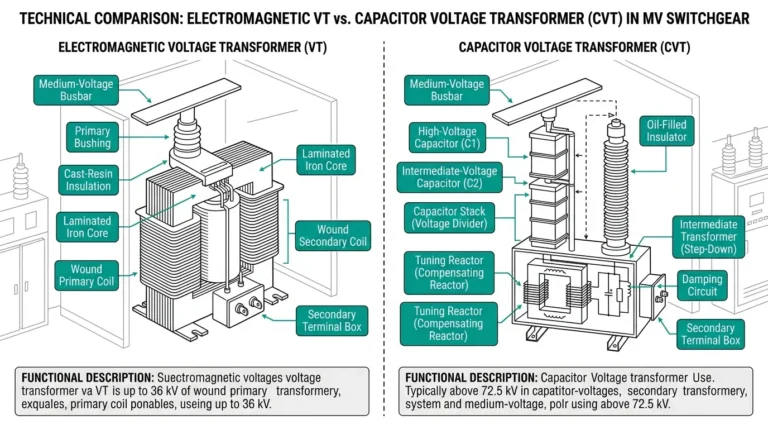
For medium-voltage capacitor bank installations, vacuum circuit breakers provide reliable switching protection during reactor testing procedures. The VS1 series offers appropriate ratings for indoor installations requiring frequent maintenance access.
Detuned capacitor banks require switching devices rated for combined capacitor-reactor duty. Vacuum contactors provide reliable switching for automatic power factor correction systems, handling capacitive current interruption without restrike issues common to air-break devices.
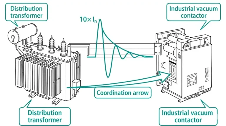
Switching transients during capacitor energization create inrush currents reaching 20–50 times rated current for durations of 1–3 milliseconds. Detuning reactors limit inrush magnitude but extend inrush duration due to added inductance. Switching devices must accommodate both parameters.
For power distribution transformers feeding capacitor banks, verify that transformer impedance does not shift the system resonant frequency toward problematic harmonic orders during varying load conditions.
Protection coordination requires:
Detuned capacitor banks demand switching equipment engineered for capacitive and harmonic duties. XBRELE manufactures vacuum contactors and vacuum circuit breakers specifically rated for power factor correction applications across voltage classes from 400 V to 40.5 kV.
Our engineering team supports capacitor switching duty verification, protection coordination with detuning reactor thermal limits, and custom voltage/current ratings matched to your installation requirements.
Contact XBRELE for vacuum contactor specifications aligned with your detuned capacitor bank requirements.
Q: How do I determine if my existing capacitor bank needs detuning reactors?
A: Measure harmonic voltage distortion at the capacitor terminals—if THD exceeds 8% or individual harmonic voltages exceed 5% of fundamental, detuning reactors are recommended to prevent resonance amplification and premature capacitor failure.
Q: What is the typical lifespan of a properly sized detuning reactor?
A: Quality detuning reactors with Class H insulation typically achieve 20–25 years of service when operated within thermal ratings and protected from moisture, though actual lifespan depends on harmonic loading severity and ambient temperature conditions.
Q: Can I retrofit detuning reactors to an existing automatic power factor correction system?
A: Retrofitting is feasible but requires verifying that capacitor voltage ratings accommodate the additional reactor voltage drop (7–14% depending on detuning factor) and that physical space permits reactor installation with adequate thermal clearances.
Q: Why does my detuning reactor hum louder during certain times of day?
A: Variable humming typically correlates with load-dependent harmonic current variations—increased harmonic content from production equipment during operational hours causes higher magnetostriction forces in the reactor core, producing louder acoustic signatures.
Q: How often should detuning reactor inductance be verified after commissioning?
A: Annual inductance measurements are recommended for standard industrial environments, with semi-annual checks for installations in high-temperature or high-harmonic environments such as steel mills, foundries, or facilities with VFD loads exceeding 50% of connected capacity.
Q: What causes detuning reactor inductance to drift over time?
A: Inductance drift primarily results from core material degradation due to thermal cycling, air gap changes in gapped iron-core designs from mechanical vibration, or inter-turn insulation breakdown causing partial winding shorts—all detectable through periodic measurement protocols.
External Authority Reference: IEEE Std 1036-2020, Guide for Application of Shunt Power Capacitors, provides comprehensive guidance on capacitor bank application including harmonic considerations and detuning practices. Available at IEEE Standards Association.