Need Full Specifications?
Download our 2025 Product Catalog for detailed drawings and technical parameters of all switchgear components.
Get CatalogDownload our 2025 Product Catalog for detailed drawings and technical parameters of all switchgear components.
Get CatalogDownload our 2025 Product Catalog for detailed drawings and technical parameters of all switchgear components.
Get Catalog
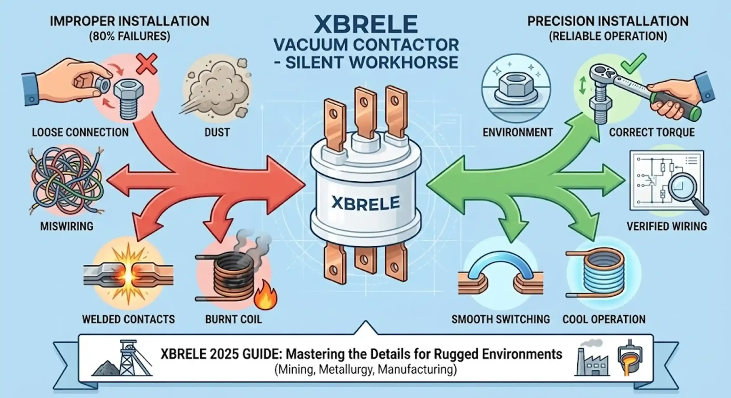
In the world of industrial power distribution, the vacuum contactor is the silent workhorse. Unlike circuit breakers, which stand guard against catastrophic faults, contactors are the marathon runners, designed to switch motors, transformers, and capacitor banks hundreds of thousands of times. However, the reliability of a vacuum contactor is only as good as its installation.
At XBRELE, we engineer our Vacuum Contactor Series to withstand the punishing environments of mining, metallurgy, and heavy manufacturing. Yet, in our decades of supporting panel builders and facility managers, we have seen that 80% of equipment failures—from welded contacts to burnt coils—stem not from manufacturing defects, but from improper installation or wiring errors.
This guide is not just a manual; it is a deep dive into the engineering principles of installing a vacuum contactor properly. Whether you are retrofitting a 12kV pump station or configuring a low-voltage mining panel, this 2026 update covers the critical details often missing from standard datasheets.
Before you unbox your XBRELE unit, it is vital to understand the technology inside. A vacuum contactor does not just “open” a circuit; it extinguishes an electrical arc in a micro-environment devoid of air.
Inside the ceramic “bottle” (the vacuum interrupter), contacts separate, and the arc is forced to extinguish at the first current zero-crossing. Because there is no air to ionize, the dielectric strength recovers almost instantly. This allows for a compact design, but it introduces specific installation challenges:
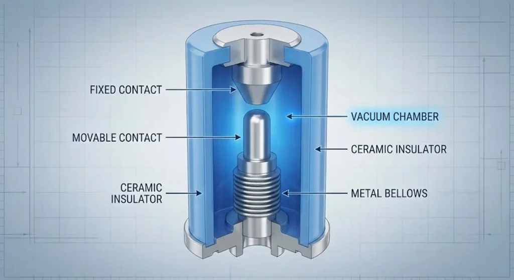
To understand the internal mechanics that dictate how you should handle these devices, read our technical breakdown: How Does a Vacuum Contactor Extinguish Arc? Inside the Vacuum Interrupter.
A vacuum contactor installed in a clean server room has a different lifespan than one in a coal mine. You must match the installation environment to the device’s capabilities.
If your facility is located above 1,000 meters (3,300 ft), standard air insulation rules change. While the vacuum inside the bottle is unaffected by altitude, the external air insulation (creepage distance between terminals) weakens as air gets thinner.
WARNING: You are likely dealing with Medium Voltage (MV) or High Voltage (HV). Arc flash hazards are lethal.
The mechanical shock of a vacuum contactor closing is significant—it acts like a solenoid hammer.
When connecting power cables (L1/L2/L3 and T1/T2/T3), use a calibrated torque wrench.
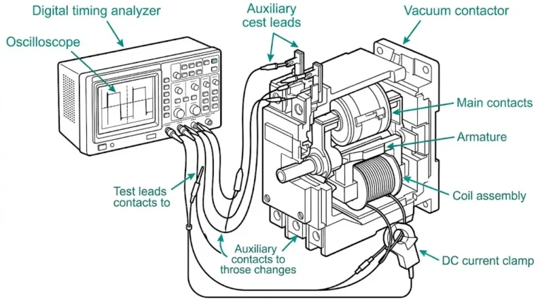
This is where the difference between a “part changer” and a “systems engineer” becomes apparent. Wiring the control logic requires understanding Self-Holding and Interlocking.
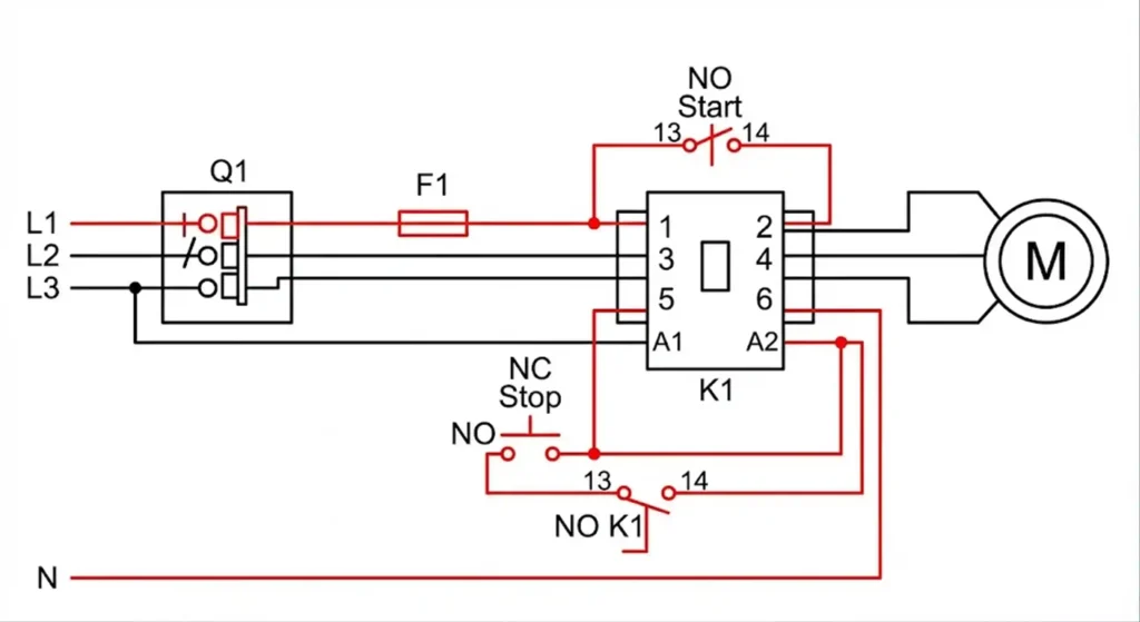
Vacuum contactors operate via an electromagnetic coil. Since the Start button is momentary (it resets when you let go), you need a “latching” circuit.
If you are using two contactors to reverse a motor, you must prevent them from closing simultaneously (a phase-to-phase dead short).
Engineer’s Note: Confused about whether you need a Vacuum Circuit Breaker (VCB) or a Contactor for your specific panel? Read our comparison:Vacuum Contactor vs Vacuum Circuit Breaker.
Updated for 2026: This article keeps the original technical framework and refreshes year-specific wording for current procurement, specification, and maintenance reference use.
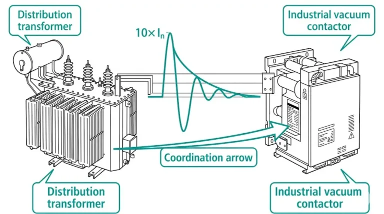
One of the most overlooked aspects of installation is handling overvoltage.
Because vacuum interrupters extinguish arcs so quickly (often chopping the current before the natural zero point), the magnetic energy stored in the motor windings has nowhere to go. This creates a massive voltage spike (Transient Recovery Voltage) that can puncture motor insulation.
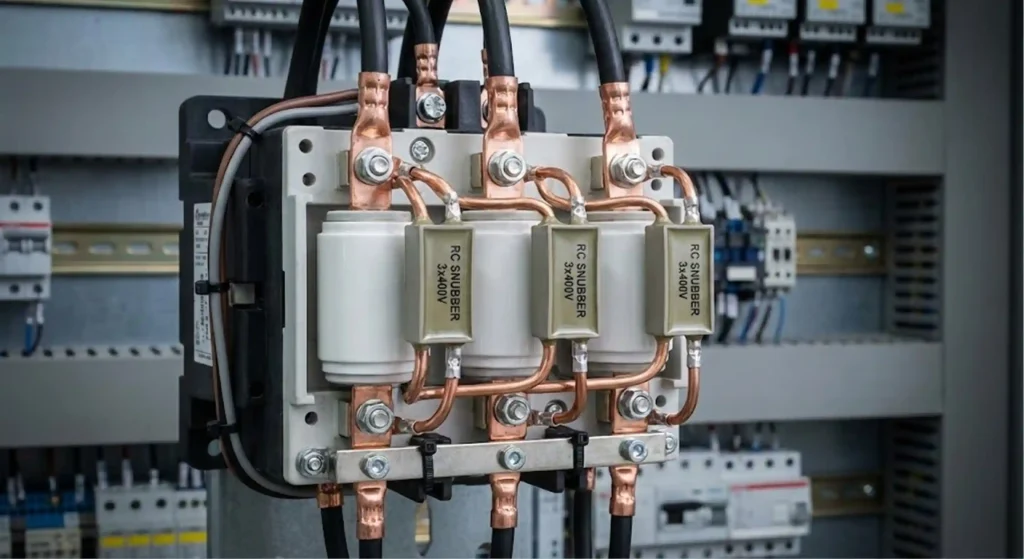
The Solution:
For inductive loads (motors/transformers), you must install a surge suppression device (RC Snubber or Zinc Oxide Varistor).
Do not energize the main high-voltage lines yet. Follow this strict protocol:
Even with the advantages of vacuum contactors, issues can arise if the environment is neglected.
| Symptom | Probable Cause | Expert Solution |
| Loud Buzzing / Chattering | Low control voltage or debris on magnet pole faces. | Check control transformer capacity. Clean the magnet surfaces (rust/dust). |
| Coil Burnout | Economizer resistor failed or wrong voltage applied. | Verify if the contactor switched from “Pull-in” to “Hold-in” mode. Check coil rating. |
| Nuisance Tripping | Vibration or loose auxiliary contacts. | Tighten all control terminals. Ensure the panel is shock-mounted if near heavy machinery. |
| High Contact Resistance | Contact wear or loose busbar connection. | Re-torque main terminals. Check contact wear indicator mark. |
Learning how to install a vacuum contactor properly is about respecting the forces at play. You are controlling massive amounts of energy with a device that relies on a vacuum gap smaller than a coin.
At XBRELE, we test every CKG and JCZ Series contactor to exceed IEC standards, but once it leaves our factory, its reliability is in your hands. By following these wiring protocols, ensuring proper torque, and installing surge protection, you ensure that your switchgear operates safely for decades.
Need a custom wiring diagram for a specific mining or industrial application?
Don’t guess. Contact the engineering team at XBRELE—your partner in high-voltage switching solutions.
1. Can I use a vacuum contactor for simple resistive heating loads?
Yes, but it is overkill. Vacuum contactors excel in AC-3 and AC-4 duties (motors with high inrush current). For simple heaters, the difference between a VCB and contactor becomes less relevant, and cost becomes the driving factor.
2. How do I know when the vacuum bottle needs replacing?
You cannot see the vacuum. However, XBRELE contactors feature a “wear line” on the insulator or armature. When the contacts erode, the mechanism travels further. Once it hits the mark, the bottle must be replaced.
3. Why does my contactor have DC coils but I feed it AC?
Many modern vacuum contactors use a rectifier bridge. This allows the coil to operate on DC, which is quieter and cooler (no eddy currents in the core), even if your supply is 220VAC. Never bypass the rectifier!
Ensure a safe and precision setup. This expert guide provides step-by-step installation procedures, comprehensive control circuit wiring diagrams, and terminal identification for MV vacuum contactors.
Download Installation Guide