Need Full Specifications?
Download our 2025 Product Catalog for detailed drawings and technical parameters of all switchgear components.
Get CatalogDownload our 2025 Product Catalog for detailed drawings and technical parameters of all switchgear components.
Get CatalogDownload our 2025 Product Catalog for detailed drawings and technical parameters of all switchgear components.
Get Catalog
Medium-voltage cable terminations fail more often than the cables they connect. In field assessments across 75+ industrial substations operating at 6.6–35 kV, improper stress cone installation accounts for approximately 40% of premature termination failures leading to partial discharge activity. The termination concentrates every installation variable—surface preparation, dimensional tolerance, interface cleanliness, environmental conditions—into a junction point where errors compound rather than average out.
This guide addresses the three questions field engineers ask most frequently: What defects cause terminations to fail? How does partial discharge develop from these defects? What acceptance tests reliably separate good installations from latent failures?
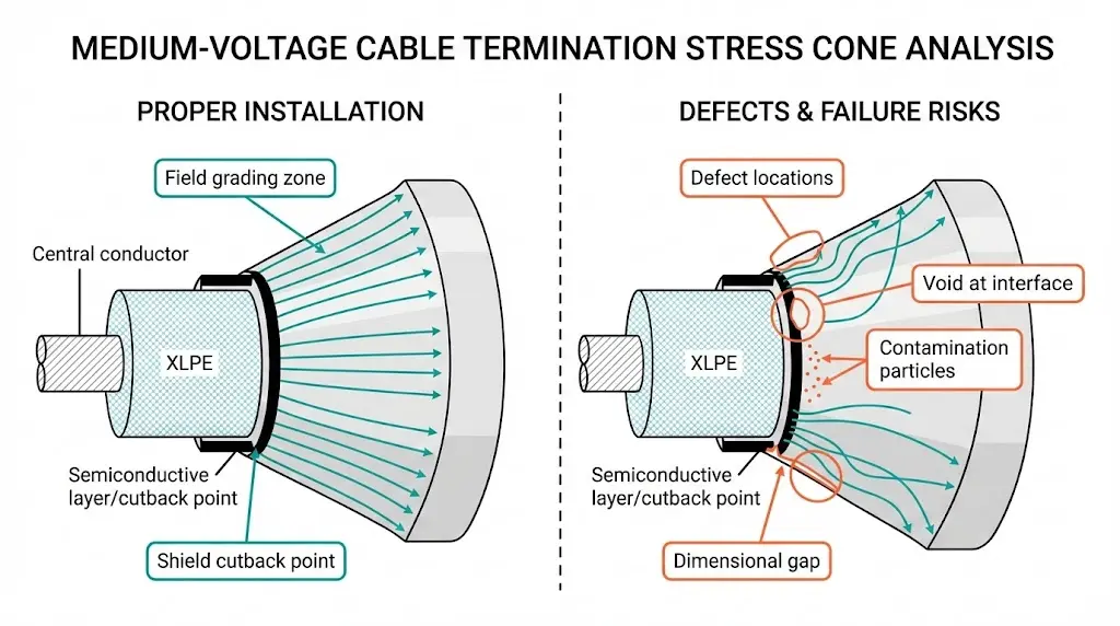
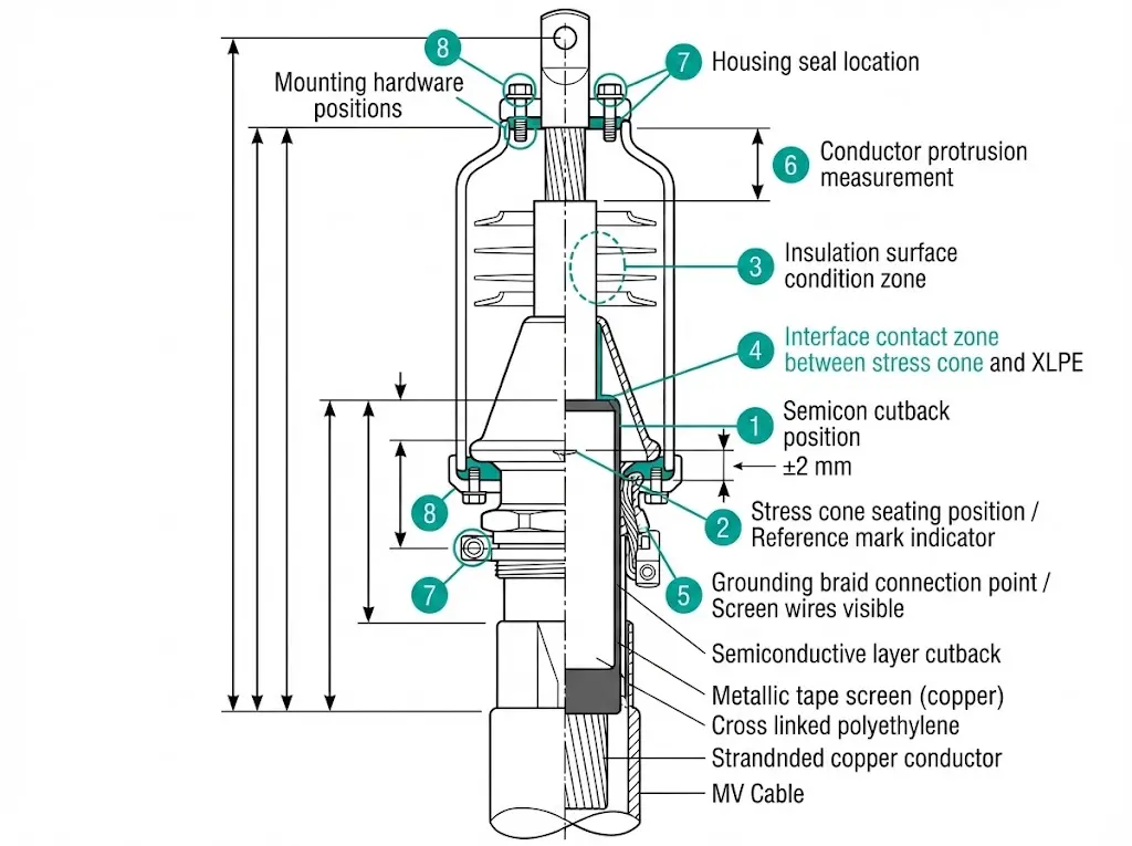
The stress cone sits at the center of each question. This component redistributes electric field intensity at the cable’s cut end, reducing peak stress from 20–30 kV/mm (ungraded) to 2–3 kV/mm (properly graded). When installation defects compromise this field grading function, partial discharge inception follows—sometimes within days, often within months.
When a medium-voltage cable is cut for termination, the semiconductive layer ends abruptly. This geometric discontinuity concentrates the electric field at the shield cutback edge. XLPE insulation withstands 20–25 kV/mm under short-term stress, but long-term reliability requires field intensity below 3–5 kV/mm. The ungraded termination operates at or beyond material limits from first energization.
The electric field magnitude at the semiconductor cutback follows the relationship: Emax = U₀ / (r × ln(R/r)), where U₀ represents phase-to-ground voltage, r is the conductor radius, and R is the insulation outer radius. Without proper stress relief, Emax values at 15 kV installations can exceed 8–10 kV/mm locally.
Stress cones solve this problem through two mechanisms. Geometric grading uses the cone’s physical shape to extend equipotential lines outward from the cable axis, spreading field intensity across a larger surface. Capacitive grading employs high-permittivity materials (εᵣ = 15–30) that absorb voltage stress through material properties rather than geometry alone.
The critical insight for troubleshooting: stress cones provide exactly the field grading required for reliable operation—no safety margin exists. Any installation defect consumes the design margin immediately. A 0.5 mm air gap at the stress cone interface experiences field stress 2.5–3× higher than surrounding material due to permittivity mismatch between air (εᵣ = 1.0) and XLPE (εᵣ = 2.3).
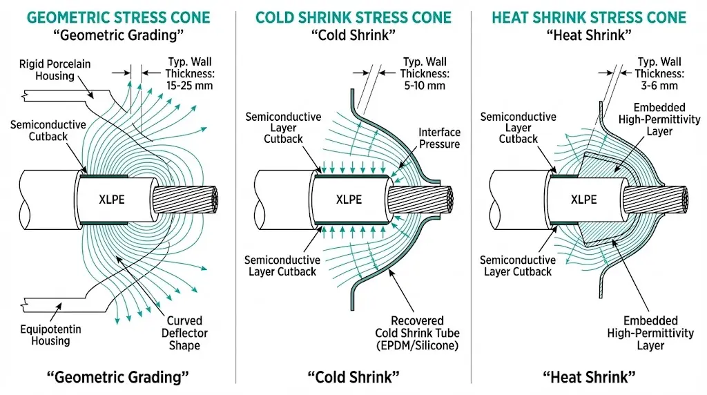
Each stress cone technology presents distinct installation vulnerabilities that field engineers must recognize during inspection and troubleshooting.
| Stress Cone Type | Grading Mechanism | Voltage Class | Critical Installation Factor | Common Failure Mode |
|---|---|---|---|---|
| Geometric (porcelain/polymer) | Physical shape extends equipotential lines | 12–36 kV | Void-free seating, precise dimensional fit | Air pockets at cone-insulation interface |
| Cold shrink (EPDM/silicone) | Pre-stretched tube recovers onto cable | 6.6–36 kV | Correct sizing within 3–5 mm diameter range | Insufficient interface pressure at range extremes |
| Heat shrink | Embedded high-permittivity compound (εᵣ = 20–30) | 6.6–24 kV | Uniform heating, complete recovery | Incomplete shrinkage, void entrapment |
| Pre-molded separable | Precision deflector geometry | 15–36 kV | Interface pressure 0.05–0.15 MPa | Contamination at separable interface |
Heat shrink terminations installed below 5°C ambient without component preheating frequently contain multiple voids. Cold shrink systems installed at the extreme edge of their diameter range lose 30–50% of designed interface pressure. These are not theoretical concerns—they represent the installation conditions we encounter repeatedly during failure investigations.
[Expert Insight: Field Observations on Stress Cone Sizing]
- Cold shrink terminations specify cable diameter ranges of 3–5 mm per size; mid-range installations consistently outperform edge-of-range installations in PD testing
- When cable diameter falls within 1 mm of the size boundary, select the smaller termination size for higher interface pressure
- Pre-installation diameter measurement at three points along the preparation length catches out-of-round cables that cause uneven stress cone contact
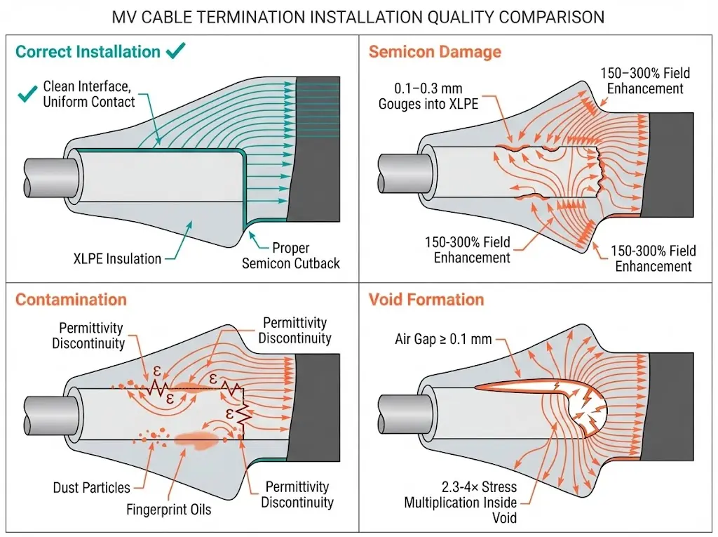
Field experience across thousands of MV cable terminations reveals consistent failure patterns. These five defects account for approximately 80% of premature failures.
Semiconductive Layer Removal Damage
Standard cable knives without depth stops frequently produce 0.1–0.3 mm gouges into the XLPE insulation surface. These gouges create local field enhancements of 150–300% above nominal values. Incomplete semiconductive removal leaves islands that create triple-junction points where air, insulation, and semiconductive material meet—partial discharge inception occurs at these locations first, typically at 60–80% of rated voltage.
Interface Contamination
A single fingerprint introduces a contamination layer 1–5 μm thick with different dielectric properties than surrounding materials. In humid environments, this contamination absorbs moisture, creating localized permittivity discontinuities. Surface discharge activity initiates at the interface—external PD measurements may show minimal activity while internal degradation progresses.
Void Formation
Voids as small as 0.1 mm diameter sustain partial discharge at operating voltage. Air-filled voids have εᵣ = 1.0 compared to 2.3–2.5 for XLPE and 3.0–4.0 for stress cone materials. The field inside the void is therefore 2.3–4.0× higher than surrounding material. For a 1 mm void in an 11 kV termination, internal void stress can reach 8–12 kV/mm—well above the 3 kV/mm breakdown strength of air.
Dimensional Mismatch
Stress cones sized incorrectly for cable diameter fail to achieve proper interface pressure. Undersized components stretch excessively, reducing wall thickness. Oversized components leave microscopic air gaps that function as distributed voids, producing broad-spectrum PD signatures rather than discrete pulses.
Grounding Connection Failures
Floating or high-resistance screen connections create voltage differences that drive capacitive currents through unintended paths. Corona discharge develops at screen wire tips or gaps in grounding connections—a defect often missed during visual inspection but readily detected during PD measurement.
| Defect Type | Visual Indicator | Field Enhancement | PD Risk Level |
|---|---|---|---|
| Semicon gouges | Visible scratches on insulation | 150–300% | High |
| Contamination | Fingerprints, dust, moisture films | 120–180% | Medium-High |
| Voids >0.1 mm | Bubbles in heat shrink, gaps in cold shrink | 230–400% | High |
| Dimensional mismatch | Excessive stretch or loose fit | 140–200% | Medium |
| Grounding failure | Loose braids, missing connections | Variable | Medium-High |
Partial discharge occurs when local electric field exceeds breakdown strength of a gas-filled cavity or contaminated surface, but the discharge does not bridge complete insulation thickness. Three PD types dominate in defective terminations.
Internal void discharge develops within enclosed cavities at the stress cone interface. The permittivity mismatch concentrates field inside the void until ionization occurs. Each discharge deposits carbon particles on void walls, gradually enlarging the conductive region until electrical treeing initiates.
Surface discharge propagates along contaminated interfaces between materials. Moisture absorption increases surface conductivity, creating preferential discharge paths. Phase-resolved patterns often show asymmetric activity influenced by surface conductivity variations.
Corona discharge develops at sharp edges or poorly grounded screen wires. Unlike void discharge, corona occurs in the ambient environment and may be audible or produce ozone odor during high-humidity conditions.
The degradation timeline varies enormously based on defect severity. Terminations operating at 90% of their partial discharge inception voltage (PDIV) may survive decades. Those operating at 150% of PDIV fail within months. The progression follows a consistent sequence: inception (weeks to months of low-magnitude activity), propagation (months to years of increasing magnitude), acceleration (weeks to months of rapid tree growth), and failure (hours to days of thermal runaway).
[Expert Insight: PD Pattern Recognition in Field Testing]
- Symmetric PD patterns in quadrants 1 and 3 typically indicate internal void discharge—remediation requires termination replacement
- Asymmetric patterns suggest surface contamination—some success with cleaning and re-termination if degradation is early-stage
- PD activity that increases with humidity points to moisture ingress at sealing interfaces
- Rising PD magnitude over successive measurements indicates active degradation requiring urgent intervention
Complete this verification before energizing any MV cable termination. Each checkpoint addresses a specific failure mechanism identified in field investigations.
Dimensional Verification
Surface Condition Assessment
Mechanical Integrity
Environmental Documentation
Three complementary tests evaluate termination quality. Each detects different defect types with varying sensitivity.
High-Voltage Withstand Testing
Apply AC or VLF test voltage at 2.0–3.0 × U₀ for 30–60 minutes [VERIFY STANDARD: IEC 60502-2 specific commissioning test voltage levels and hold times]. VLF testing at 0.01–0.1 Hz reduces capacitive charging current requirements, enabling field testing with portable equipment. Withstand testing confirms gross insulation integrity but may not detect incipient defects operating below breakdown threshold.
Partial Discharge Measurement
PD testing provides direct evidence of defect presence. Sensitivity requirement: ≤10 pC detection capability at termination location. Acceptance threshold: typically <5 pC for new installations, though utility-specific requirements vary. Measure during voltage ramp-up to identify PDIV; measure during ramp-down to confirm PD extinction voltage (PDEV). A termination showing PDIV below 1.5 × U₀ requires investigation regardless of absolute PD magnitude.
Tan Delta / Dissipation Factor
Measure at 0.5 × U₀, 1.0 × U₀, and 1.5 × U₀. Tip-up (increase in tan δ with voltage) indicates contamination or void presence. Typical acceptance for new XLPE systems: tan δ < 0.1% with tip-up < 0.05% between voltage steps. This test evaluates overall insulation condition including terminations but cannot localize defects.
| Test Method | Primary Detection | Acceptance Threshold | Defect Localization |
|---|---|---|---|
| HV Withstand | Gross insulation failure | No breakdown at test voltage | None |
| PD Measurement | Voids, contamination, tracking | <5 pC at 1.5 × U₀ | Good (with multiple sensors) |
| Tan Delta | Distributed degradation, moisture | <0.1%, tip-up <0.05% | Poor |
Prevention costs less than remediation. These controls reduce defect rates measurably.
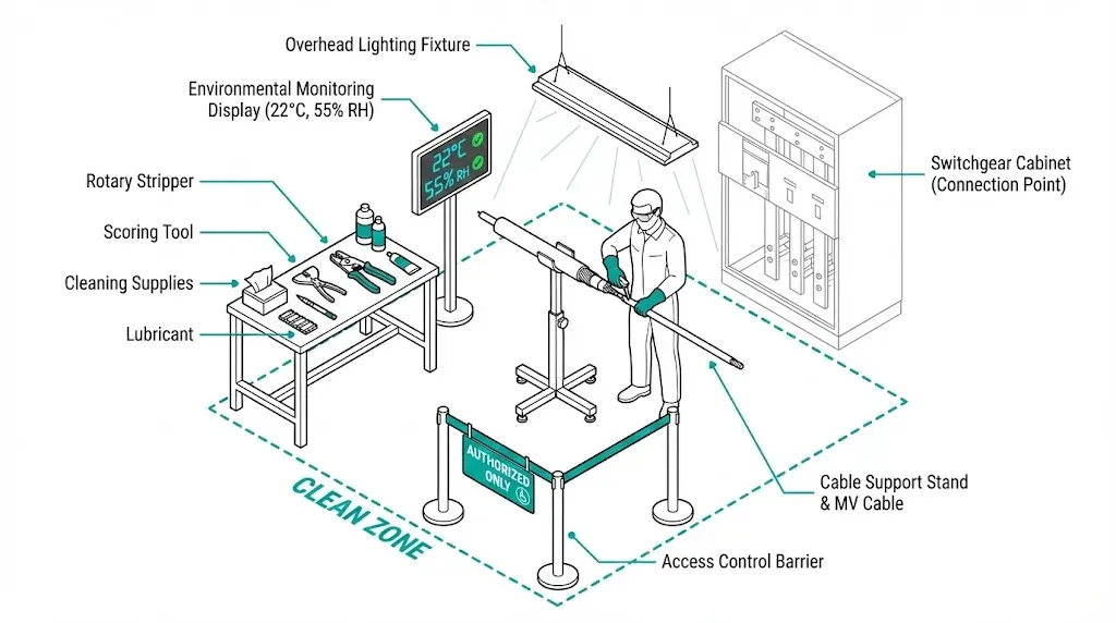
Environmental Requirements
Maintain ambient temperature between 10–35°C during installation. Below 10°C, preheat cold shrink components and cable end per manufacturer instructions. Keep relative humidity below 70% at the work location—use portable dehumidifiers or temporary enclosures when necessary. Establish a defined clean zone with controlled access; prohibit eating, smoking, and unnecessary traffic.
Tool Standards
Rotary cable stripping tools with adjustable depth stops eliminate insulation gouging. Semiconductive scoring tools create consistent, perpendicular edges. Use only manufacturer-specified cleaning solvents and lint-free wipes. Apply approved lubricants in specified quantities—excess lubricant causes as many problems as insufficient lubricant.
Installer Certification Impact
Certified installers reduce defect rates by 60–80% compared to uncertified personnel. Major termination manufacturers offer certification programs requiring classroom training, supervised hands-on installation, practical examination, and periodic recertification every 2–3 years. For critical infrastructure, specify certified installers in procurement documents: “All MV cable terminations shall be installed by personnel holding current certification from the termination manufacturer.”
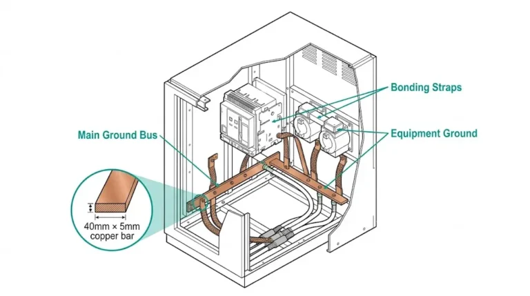
MV cable terminations interface directly with switchgear bushings and cable compartments. XBRELE’s vacuum circuit breakers are engineered with cable termination compatibility as a design priority—bushing dimensions, clearances, and mounting provisions accommodate standard termination systems without field modification.
Our switchgear components support the long-term integrity that proper termination installation establishes. When cable systems connect to equipment designed for reliable interfaces, the investment in quality termination work delivers its full service life value.
For technical consultation on termination compatibility with XBRELE switchgear, or to discuss vacuum interrupter technology for your medium-voltage applications, contact our engineering team. We provide guidance on indoor versus outdoor installations where termination requirements differ significantly.
What causes most MV cable termination failures?
Interface contamination and void formation together account for 60–70% of premature failures based on failure analysis data from multiple utilities. Both defects result from inadequate surface preparation or improper component installation rather than material deficiencies.
How quickly can a defective termination fail after installation?
Severely defective terminations with voids larger than 1 mm or gross contamination can fail within weeks. Marginal defects typically require 2–5 years to progress through the full degradation sequence, with actual timeline depending on operating voltage relative to PDIV and environmental conditions.
Can partial discharge testing detect all termination defects?
PD testing reliably detects voids, contamination, and tracking defects that have initiated discharge activity. However, defects operating below their inception voltage—such as marginal dimensional mismatches—may not produce detectable PD until voltage stress increases or environmental conditions change.
What temperature range is acceptable for cold shrink termination installation?
Most manufacturers specify 10–35°C ambient temperature. Installations below 10°C require preheating components and cable ends to ensure proper material recovery and adequate interface pressure. Installations above 35°C may cause premature tube recovery before proper positioning.
How small a void causes partial discharge problems?
Voids as small as 0.1 mm diameter can sustain PD activity at typical MV operating voltages when located in high-stress regions. The critical factor is not void size alone but the combination of void location, local field intensity, and gas composition within the void.
Is VLF testing equivalent to power frequency testing for commissioning?
VLF testing at 0.01–0.1 Hz is widely accepted as equivalent to power frequency testing for extruded insulation systems including XLPE cables and terminations. IEEE 400.2 provides guidance on VLF test procedures and acceptance criteria for field testing of shielded power cable systems.
External Reference: IEEE 48-2009, Standard for Test Procedures and Requirements for Alternating-Current Cable Terminations — IEEE Standards Association