Need Full Specifications?
Download our 2025 Product Catalog for detailed drawings and technical parameters of all switchgear components.
Get CatalogDownload our 2025 Product Catalog for detailed drawings and technical parameters of all switchgear components.
Get CatalogDownload our 2025 Product Catalog for detailed drawings and technical parameters of all switchgear components.
Get Catalog
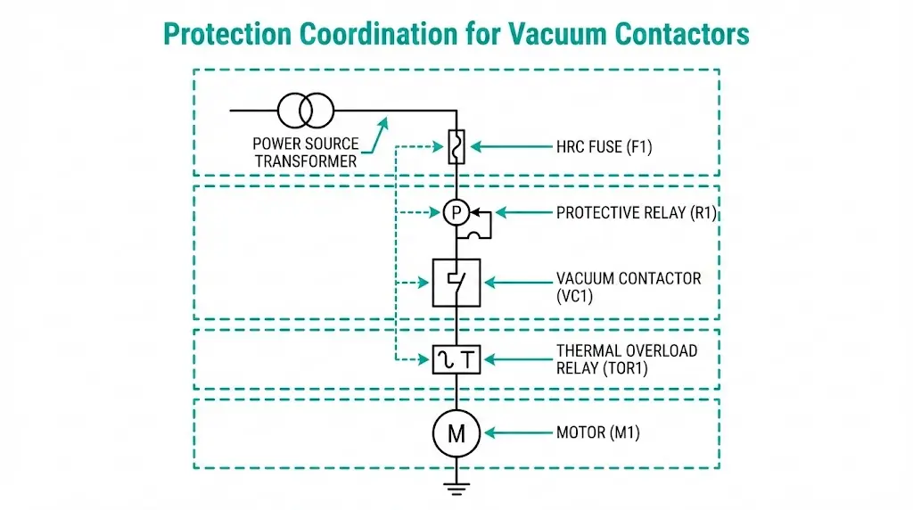
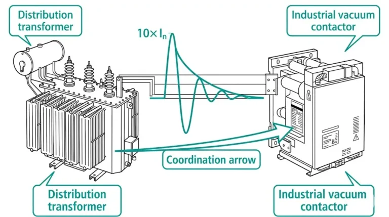
Protection coordination between fuses, relays, and overload devices determines whether a vacuum contactor survives fault conditions or suffers contact welding, arc damage, or complete failure. The coordination principle is straightforward: each protective device must operate within its designated zone before upstream devices respond, isolating faults at the nearest protection point while preserving service to unaffected circuits.
In field deployments across 200+ industrial motor control centers, we’ve documented that improper coordination causes approximately 30% of unplanned production shutdowns—even when individual devices meet their rated specifications. This guide provides practical coordination methodology for engineers designing and commissioning vacuum contactor protection schemes.
Vacuum contactors excel at switching loads repeatedly under normal operating conditions. A well-designed unit handles 100,000 to 1,000,000 mechanical operations depending on load category. But this switching capability has hard limits.
The breaking capacity of a typical medium-voltage vacuum contactor designed for frequent switching operations falls between 8× and 10× rated current for AC-3 (motor running) or AC-4 (motor starting/plugging) duty. For a 400 A contactor, that translates to roughly 3,200–4,000 A maximum interrupting current.
Compare that figure against prospective fault current at an industrial MV bus. Values of 20–40 kA are common. Some installations see 50 kA or higher.
The mismatch is severe. When fault current exceeds the contactor’s breaking capacity:
IEC 60947-4-1 defines utilization categories precisely because contactors are not fault-interrupting devices. The standard distinguishes between making capacity (closing onto a fault) and breaking capacity (opening under fault). Both ratings remain far below system fault levels in most MV applications.
This gap creates an absolute requirement: backup protection devices must interrupt faults before the contactor attempts interruption beyond its rating.
Current-limiting fuses serve as the first line of defense against prospective fault currents exceeding the vacuum contactor’s breaking capacity. Proper fuse selection requires matching the fuse’s I²t let-through characteristics to the contactor’s thermal withstand capability.
Three fuse categories apply to vacuum contactor protection:
Type gG/gL fuses provide full-range protection covering both overload and short-circuit conditions. These general-purpose fuses suit applications where moderate fault clearing times are acceptable.
Type aM fuses are motor-rated devices designed to withstand starting inrush currents while providing short-circuit protection. They do not protect against overloads—a separate overload relay handles that function.
Type aR fuses offer semiconductor-style fast action, clearing faults within 5 ms at prospective currents above 20 kA. Mining and petrochemical installations favor this combination for motor feeders where fault current contributions create severe prospective levels.
The coordination margin between fuse and contactor follows the relationship:
Fuse I²tlet-through ≤ Contactor I²twithstand
For a typical high-voltage contactor application rated at 400 A operational current, the maximum permissible fuse I²t during fault clearing should not exceed the contactor’s withstand value—typically 40,000–50,000 A²s for standard industrial units.
Table: Fuse-Contactor Coordination Example
| Parameter | Value |
|---|---|
| Contactor rated current | 400 A |
| System voltage | 7.2 kV |
| Prospective fault current | 25 kA |
| Contactor I²t withstand | 50,000 A²s |
| Selected fuse rating | 250 A HRC |
| Fuse I²t @ 25 kA | 35,000 A²s |
| Coordination status | ✓ Protected |
Field testing in mining operations demonstrated that fuse ratings should not exceed 125% of the vacuum contactor’s thermal rating. When fuse clearing time at maximum fault current drops below 10 ms, the contactor experiences minimal arc energy during the fault event, extending contact service life by 40–60% compared to poorly coordinated systems.

[Expert Insight: Fuse Selection in Practice]
- Select fuses with I²t values at least 20% below contactor withstand ratings to account for manufacturing tolerances
- Verify fuse performance at actual ambient temperature—I²t increases by 5–8% at 40°C versus 25°C rated conditions
- Replace fuses from the same manufacturer’s lot to maintain consistent coordination characteristics
- Document fuse model and batch numbers in coordination study records for future reference
Protective relays provide adjustable time-current characteristics that coordinate with both upstream fuses and downstream thermal overloads. Unlike fuses, relays can be reset and their settings adjusted to match changing system conditions.
Inverse Definite Minimum Time (IDMT) relays follow IEC standard curves—Standard Inverse (SI), Very Inverse (VI), Extremely Inverse (EI), and Long-Time Inverse (LTI). The relay operating time decreases as fault current increases, following a defined mathematical relationship.
Definite-time relays provide fixed time delays regardless of current magnitude above pickup. These suit applications requiring predictable clearing times independent of fault severity.
Instantaneous relays operate without intentional delay for high-magnitude faults. Pickup settings typically range from 6× to 12× full-load current to avoid tripping on motor starting inrush.
Total fault clearance time includes multiple components:
The relay must trip before the contactor’s thermal damage threshold at all fault current levels. According to IEC 60947-4-1 coordination requirements, Type 2 coordination demands that the contactor remain operational after fault clearing without contact welding or permanent damage.
Coordination Workflow:

A common misunderstanding: overload relays protect the load (motor windings, capacitor dielectric), not the vacuum contactor itself. The contactor still requires upstream fuse or circuit breaker protection against fault currents exceeding its breaking capacity.
Thermal overload relays use bimetallic elements that deflect under sustained current flow. Trip classes define response time:
Electronic overload relays provide programmable trip curves, phase loss detection, ground fault monitoring, and thermal memory functions. Digital communication capabilities enable remote monitoring and setting adjustment.
The complete protection stack operates as follows:
In enclosed motor control centers operating at 40°C ambient, overload settings require 10–15% reduction from nameplate values. The vacuum contactor’s reliable making and breaking capacity depends directly on proper overload protection preventing sustained overcurrent conditions that accelerate contact erosion.

[Expert Insight: Overload Relay Commissioning]
- Verify CT polarity and ratio before energizing electronic overload relays
- Test phase-loss protection by disconnecting one phase at reduced voltage during commissioning
- Set ground fault pickup at 50–100 mA for personnel safety in wet environments
- Document ambient temperature at commissioning—thermal relays require recalibration if operating temperature differs by more than 10°C
Different applications impose distinct coordination challenges. Motor starting inrush, capacitor energization transients, and transformer magnetizing current each require specific protection strategies.
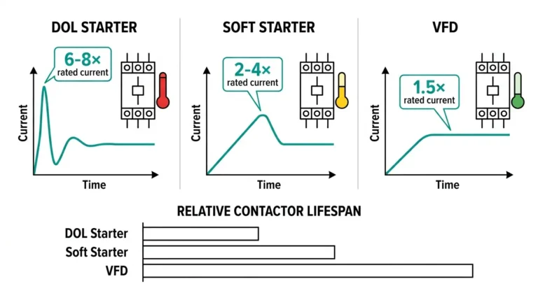
Motor starting produces inrush currents of 6–8× full-load amperes for 5–15 seconds during direct-on-line acceleration. Locked rotor conditions sustain this current level until protection operates.
The coordination challenge: protection must ride through normal starting inrush while tripping on locked rotor or stall conditions. Type aM fuses combined with Class 20 thermal overloads provide this discrimination for most industrial motor applications.
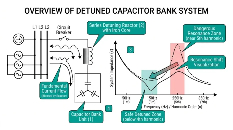
Capacitor switching with vacuum contactors creates severe transient conditions. Energization inrush can exceed 100× rated current for durations under 1 ms. Back-to-back switching—energizing one capacitor bank while others remain connected—produces even higher peaks.
Restrike during de-energization presents additional hazards. If the vacuum contactor restrikes after initial arc extinction, the resulting voltage transient can damage capacitor dielectric and connected equipment.
Coordination approach: current-limiting reactors reduce inrush peak magnitude; fast-acting current-limiting fuses clear faults before contactor damage; point-on-wave switching controllers minimize transient severity.
Transformer magnetizing inrush reaches 8–12× rated current with asymmetrical waveform characteristics. The second-harmonic content of inrush current distinguishes it from fault current—protective relays with harmonic restraint prevent false tripping during energization.
Table: Application Coordination Summary
| Application | Overload Device | Short-Circuit Device | Key Challenge |
|---|---|---|---|
| Motor starter | Class 20 thermal | aM fuse | Inrush ride-through |
| Capacitor bank | Typically none | Current-limiting fuse | Transient peak, restrike |
| Transformer feeder | IDMT relay | gG/gL fuse | Magnetizing inrush |

Real-world coordination problems stem from design errors, improper settings, or system changes that invalidate original coordination studies.
Oversized fuses: Engineers sometimes select fuses with excessive “safety margins.” A 400 A fuse protecting a 200 A contactor may not clear faults quickly enough to prevent contact welding. The fuse must be sized to coordinate with the contactor’s actual withstand capability, not arbitrarily oversized.
Relay timing mismatch: When relay operating time exceeds the contactor’s thermal withstand at high fault currents, the contactor suffers damage before the relay trips. This failure mode becomes apparent only during actual fault events.
Instantaneous element trips on inrush: Motor starting or capacitor energization produces brief current peaks that exceed instantaneous relay pickup settings. Nuisance tripping disrupts production without any actual fault condition.
Auto-reset overload cycling: Automatic reset overloads permit repeated restarting of overheated motors. The contactor operates normally while motor windings accumulate thermal damage with each restart cycle.
No discrimination study: When multiple devices trip simultaneously during a fault, locating the actual fault point becomes difficult. Production recovery time increases dramatically.
Field Case Example:
A 7.2 kV vacuum contactor in a cement plant capacitor bank experienced restrike during opening. The backup fuse was sized correctly for bolted fault clearing but not for the transient recovery voltage following restrike. Result: contactor destroyed, fuse intact—exactly opposite from intended coordination. Post-incident analysis revealed that the alternative high-voltage contactor series with enhanced restrike suppression would have survived the same event.
Accurate coordination requires precise device specifications. XBRELE provides complete technical datasheets for all vacuum contactor series, including:
For critical applications in mining, petrochemical, or water treatment facilities, XBRELE engineering support assists with coordination verification, protection device selection, and commissioning guidance.
Contact the XBRELE vacuum contactor manufacturing team for coordination datasheets, time-current characteristic curves, or application-specific technical support.
Q: What happens if I select a fuse rated higher than the vacuum contactor’s thermal withstand?
A: The fuse may not clear faults quickly enough to prevent contact welding—the contactor sustains damage while the oversized fuse remains intact, requiring both contactor replacement and root cause investigation.
Q: How do I verify coordination between relay and contactor during commissioning?
A: Inject secondary current into the relay using a test set, measure actual trip times at multiple current levels (typically 3×, 5×, and 10× pickup), and compare results against the contactor’s published thermal damage curve.
Q: Can thermal overload relays protect vacuum contactors from short circuits?
A: No—thermal overloads operate too slowly for fault protection, with trip times measured in seconds rather than milliseconds. Fuses or circuit breakers must provide short-circuit backup protection.
Q: What coordination margin should I maintain between protection devices?
A: Most industrial applications require minimum 0.3-second separation between time-current curves at maximum fault current to ensure selective operation under transient conditions and account for relay timing tolerances.
Q: Why do capacitor bank applications require special coordination considerations?
A: Capacitor energization produces transient currents exceeding 100× rated current for sub-millisecond durations, and restrike during de-energization creates voltage transients that standard protection schemes cannot address without current-limiting reactors and fast-acting fuses.
Q: How often should protection coordination studies be reviewed?
A: Coordination studies require review whenever system changes occur—new loads added, transformers upgraded, fault levels recalculated, or protective devices replaced—with periodic verification every 3–5 years even without system modifications.
Q: What documentation should I maintain for protection coordination?
A: Keep time-current coordination plots showing all device curves, relay setting sheets with pickup and time dial values, fuse specification sheets with I²t data, and records of ambient temperature and system fault levels at commissioning.