Precisa das especificações completas?
Faça o download do nosso Catálogo de Produtos 2025 para obter desenhos detalhados e parâmetros técnicos de todos os componentes do quadro elétrico.
Obter catálogo
Faça o download do nosso Catálogo de Produtos 2025 para obter desenhos detalhados e parâmetros técnicos de todos os componentes do quadro elétrico.
Obter catálogo Faça o download do nosso Catálogo de Produtos 2025 para obter desenhos detalhados e parâmetros técnicos de todos os componentes do quadro elétrico.
Obter catálogo
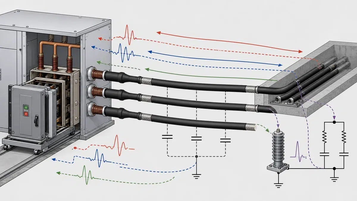
Os disjuntores a vácuo conquistaram uma posição dominante nas redes de distribuição de média tensão devido à sua forma compacta, às baixas exigências de manutenção e ao desempenho confiável na extinção do arco. Ainda assim, uma condição específica — a **comutação da corrente de carga de cabos por VCB** — continua sendo motivo de preocupação de engenharia e é frequentemente subestimada durante o projeto do sistema. Quando um VCB interrompe a pequena corrente capacitiva absorvida por um cabo sem carga, a rápida recuperação da tensão no interruptor a vácuo pode interagir com a capacitância do cabo e gerar sobretensões perigosas. No pior caso, ocorrem reignições repetidas do arco, que submetem o disjuntor e os equipamentos conectados a esforços.
Este artigo examina os mecanismos físicos por trás da reignição, o sistema de classificação que rege a adequação do VCB a serviços capacitivos, as estratégias de controle de surtos disponíveis aos projetistas e os fatores específicos do local que determinam a combinação de medidas apropriada para cada instalação.
—
Quando um VCB abre em um cabo sem carga, ele interrompe uma carga puramente capacitiva. A corrente é pequena — muitas vezes apenas algumas dezenas de ampères —, mas sua relação de fase com a tensão do sistema cria uma condição potencialmente perigosa após a interrupção. No instante de corrente zero, que o interruptor a vácuo aproveita para extinguir o arco, a tensão no cabo está no pico ou perto dele. Já a tensão do lado da fonte continua oscilando na frequência do sistema.
Dentro de meio ciclo após a interrupção, a tensão da fonte atinge o pico de polaridade oposta. Portanto, a tensão nos contatos abertos é aproximadamente o dobro do pico do sistema. Se o interruptor a vácuo não suportar essa tensão transitória de restabelecimento (TRV), o vão entre os contatos volta a romper — evento chamado **reignição** (restrike). Cada reignição injeta no cabo um pulso de corrente de alta frequência e, quando esse pulso é novamente interrompido, pode ocorrer um aumento de tensão, às vezes descrito como multiplicação da tensão ou sobretensão por reignição. Em casos graves, reignições sucessivas podem elevar as tensões fase-terra a várias vezes o pico nominal, ameaçando o isolamento dos cabos, para-raios, transformadores e motores conectados a jusante.
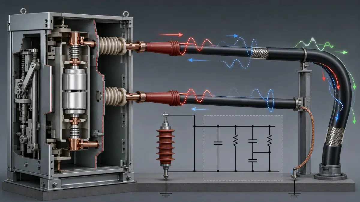
A probabilidade de reignição é determinada pela relação entre a taxa de recuperação da rigidez dielétrica (RRDRS) do interruptor a vácuo e a taxa de crescimento da TRV. A tecnologia a vácuo oferece uma RRDRS muito alta — uma de suas principais vantagens em relação ao SF₆ neste contexto —, mas a vantagem não é incondicional. O material dos contatos, a velocidade de separação dos contatos, o histórico de arcos anteriores e a magnitude da tensão de restabelecimento prevista influenciam a ocorrência de reignição.
—
A norma IEC 62271-100 introduziu uma abordagem estruturada para caracterizar a adequação de um disjuntor às operações de comutação capacitiva. São definidas duas classes:
As orientações técnicas da Schneider Electric deixam claro que a classificação C1 ou C2 se refere à baixa probabilidade de reignição durante a interrupção de corrente capacitiva, demonstrada por ensaios de tipo, enquanto as condições reais de serviço dependem da tensão e da aplicação específica de cada instalação (FAQ Schneider FA352797). Este é um ponto prático importante: um VCB com classificação C2 oferece maior garantia que um dispositivo C1, mas as condições do ensaio de tipo podem não reproduzir todas as combinações de comprimento do cabo, impedância do sistema e tensão operacional encontradas em campo. A classificação é um ponto de partida necessário, não uma garantia de que dispensam-se medidas de proteção.
Ao especificar um VCB para operações frequentes de energização e desenergização de cabos, os projetistas devem confirmar a classe aplicável, verificar se a corrente nominal de comutação capacitiva cobre a corrente de carga real do cabo e avaliar em seguida, com base nos detalhes da instalação, se é necessário controle adicional de surtos.
—
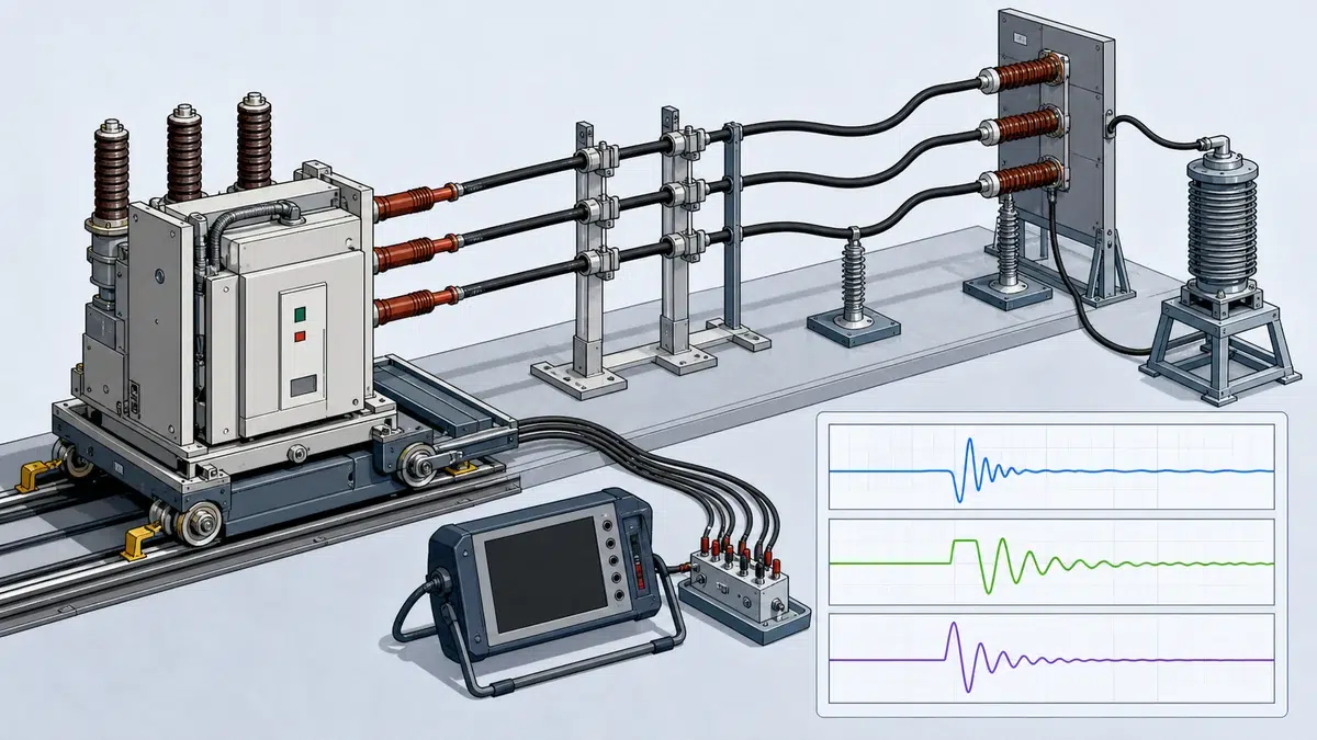
O comprimento do cabo é uma das variáveis mais influentes na avaliação do risco de reignição, pois determina diretamente a carga capacitiva armazenada no alimentador. Uma derivação curta de 200 metros apresenta uma condição muito diferente de uma linha subterrânea principal com um quilômetro. Cabos mais longos armazenam mais carga, portanto a energia injetada no sistema durante uma reignição é maior e o potencial de elevação da tensão também aumenta.
Além do comprimento, o tipo de cabo é importante. Cabos isolados em XLPE têm menor capacitância por unidade de comprimento do que os antigos cabos isolados em papel com bainha de chumbo, mas os cabos modernos de XLPE são usados em trechos cada vez mais longos à medida que as redes se expandem. A presença de várias seções de cabo em paralelo — comum em redes em anel ou malhadas — multiplica a capacitância efetiva vista pelo dispositivo de comutação.
A documentação de engenharia da Schneider para o disjuntor de média tensão EvoPacT reconhece especificamente que a capacitância de cabos longos pode afetar o comportamento da proteção contra surtos e que sistemas MT complexos podem exigir um estudo detalhado de sobretensão e a implementação de uma rede RC, cujo projeto específico deve ser definido pela análise do sistema (Guia do Usuário Schneider EvoPacT). Essa orientação registra uma realidade importante da engenharia: nenhuma solução única de controle de surtos pode ser especificada universalmente. A interação entre a capacitância do cabo, a indutância da fonte, a capacidade de absorção de energia dos para-raios e a impedância da rede de amortecimento RC deve ser avaliada em conjunto. O guia do usuário Schneider Electric EvoPacT é a fonte primária para o requisito específico do produto mencionado aqui.
Da mesma forma, as orientações de aplicação da ABB para seleção de dispositivos de comutação MT confirmam que o chaveamento de alimentadores aéreos e de cabos com disjuntores a vácuo pode exigir medidas para limitar sobretensões em algumas circunstâncias (Guia de Aplicação ABB para Dispositivos de Comutação MT, 1VGA671056). A ressalva “em algumas circunstâncias” é intencional: a necessidade de proteção adicional depende da aplicação, e muitas operações rotineiras não apresentam problema prático quando se seleciona um VCB C2 dimensionado corretamente. Os casos extremos — alimentadores longos, chaveamentos frequentes e equipamentos terminais sensíveis — exigem mais atenção. Para opções de equipamento e configuração, compare as condições de serviço do projeto com a gama de produtos VCB de média tensão.
—
Há várias medidas para controlar as sobretensões associadas à comutação da corrente de carga de cabos por VCB. Cada uma tem um mecanismo próprio e uma relação diferente entre custo e benefício.
**Redes RC de amortecimento (snubbers)**
Uma rede RC conectada aos terminais do VCB introduz um elemento resistivo que amortece as oscilações de alta frequência após a interrupção. O resistor limita a amplitude da corrente de reignição e reduz o pico de qualquer sobretensão subsequente. O capacitor fornece um caminho de baixa impedância para o transitório de alta frequência, impedindo sua propagação para a rede a montante. Redes RC são amplamente usadas em aplicações de chaveamento de motores e também se aplicam a operações em cabos, sobretudo quando cabos longos criam valores elevados de capacitância que poderiam exceder a capacidade de absorção de energia do para-raios. A seleção dos valores RC é específica do sistema e exige conhecimento da capacitância do cabo, da indutância da fonte e da frequência do modo oscilatório dominante.
**Para-raios de óxido metálico (MOSA)**
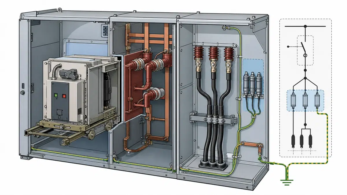
Os para-raios limitam sobretensões conduzindo corrente quando a tensão sobre eles excede seu nível de proteção. Em aplicações de comutação de cabos, normalmente são instalados no terminal do cabo e no barramento do lado da carga do disjuntor. Sua eficácia depende da capacidade nominal de absorção de energia: uma reignição injeta um pulso considerável de energia em alta frequência, e um para-raios subdimensionado pode operar fora de sua classe energética nominal, com risco de fuga térmica. Quando redes RC e para-raios são usados em conjunto, o esforço sobre o para-raios diminui porque a rede RC limita a amplitude inicial da sobretensão. Confira os campos de serviço e da placa de identificação com a referência de dados nominais do VCB antes da aceitação.
**Resistores de pré-inserção**
Resistores de pré-inserção (PIR) são usados principalmente em transitórios de energização no chaveamento de bancos de capacitores, mas o conceito também tem aplicação análoga no chaveamento de cabos. Ao inserir brevemente um resistor durante o curso de fechamento, a corrente de energização e o transitório de tensão associado são amortecidos. Para a desenergização, a abordagem equivalente — abertura controlada — é mais pertinente: alguns VCBs modernos incorporam a capacidade de chaveamento point-on-wave (POW), que sincroniza a separação dos contatos com o ponto ideal da forma de onda da corrente para minimizar a severidade da TRV. Se um comando ou o resultado do mecanismo for anormal, consulte o guia de resolução de problemas de fecho e abertura do VCB.
**Chaveamento controlado (point-on-wave)**
Os controladores de chaveamento controlado atrasam ou adiantam a operação mecânica do VCB para que a separação dos contatos ocorra em um ângulo de fase no qual a TRV subsequente seja minimizada. Na comutação de carga capacitiva, normalmente isso significa posicionar a separação dos contatos perto de um zero de corrente, quando as tensões do lado da fonte e do lado da carga apresentam uma relação favorável. O chaveamento controlado é uma técnica avançada que exige um controlador confiável e comissionamento cuidadoso, mas pode reduzir substancialmente a probabilidade de reignição sem alterar o hardware do VCB.
—
Um processo de avaliação estruturado reduz o risco tanto de superdimensionar a engenharia, acrescentando uma proteção desnecessária e cara, quanto de proteger insuficientemente um sistema em que reignições podem causar danos aos equipamentos ou interrupções. As etapas seguintes descrevem um fluxo prático.
**Etapa 1 — Caracterize o cabo.**
Determine o comprimento total do cabo, o tipo, a capacitância por unidade de comprimento e todos os caminhos em paralelo. Calcule a corrente de carga trifásica total na tensão de operação e compare-a com a corrente nominal de comutação capacitiva do VCB.
**Etapa 2 — Confirme a classe do VCB.**
Verifique se o VCB selecionado tem classificação C1 ou C2 conforme a IEC 62271-100 e se a corrente nominal de comutação capacitiva supera a corrente de carga calculada do cabo com margem adequada. Para aplicações com cabos longos ou chaveamento frequente, geralmente é preferível a classe C2.
**Etapa 3 — Avalie a impedância do sistema e a TRV.**
Use os dados da rede para calcular o pico e a taxa de crescimento da TRV. Compare-os com a capacidade nominal de TRV do VCB. Quando a TRV é dominada pela reatância do transformador e por um cabo longo, seu perfil pode ser mais severo que a forma de onda de ensaio padrão.
**Etapa 4 — Avalie a sensibilidade dos equipamentos a jusante.**
Máquinas rotativas, acionamentos eletrônicos de potência e sistemas antigos de isolamento de cabos são mais sensíveis a transitórios de sobretensão do que transformadores a seco modernos. Identifique as cargas sensíveis e seus níveis de suportabilidade previstos.
**Etapa 5 — Faça um estudo de sobretensão para sistemas complexos.**
Como enfatizado na literatura técnica da Schneider, sistemas MT complexos justificam um estudo formal de sobretensão usando simulação de transitórios eletromagnéticos (EMTP ou equivalente). O estudo deve modelar os parâmetros distribuídos do cabo, a característica de reignição do VCB e quaisquer dispositivos de proteção contra surtos existentes.
**Etapa 6 — Selecione e projete as medidas de controle de surtos.**
Com base nos resultados do estudo, especifique para-raios (com classe energética verificada), redes RC (com valores de R e C calculados) ou chaveamento controlado. Confirme que a combinação atende aos requisitos de suportabilidade dos equipamentos conectados mais sensíveis.
**Etapa 7 — Especifique os requisitos de ensaio e comissionamento.**
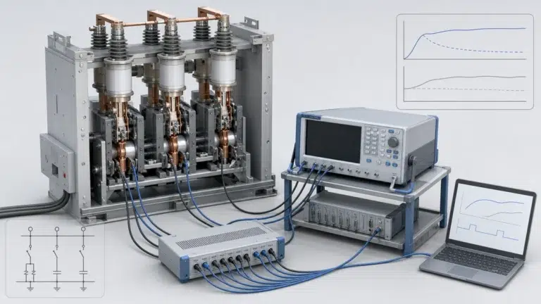
Sempre que forem instaladas redes RC ou controladores de chaveamento controlado, inclua ensaios de aceitação em fábrica (FAT) e no local (SAT) para verificar a operação correta antes da energização. A lista de verificação de aceitação do VCB oferece uma estrutura complementar para critérios de aceitação, resultados e registros de encerramento.
—
Reignição e re-ignição referem-se ao restabelecimento do arco após um zero de corrente, mas a IEC 62271-100 as distingue pelo momento em que ocorrem. Uma re-ignição ocorre durante o primeiro quarto de ciclo após a interrupção da corrente (menos de aproximadamente 5 milissegundos a 50 Hz), enquanto uma reignição ocorre depois desse intervalo. No contexto da comutação da corrente de carga de cabos por VCB, as reignições são a preocupação mais significativa porque ocorrem quando a tensão entre os contatos já atingiu ou se aproximou da tensão de restabelecimento total. Nesse momento, a energia disponível para sustentar o arco e gerar sobretensão na interrupção é máxima. As re-ignições, embora indesejáveis, ocorrem com tensões de restabelecimento menores e geralmente produzem transitórios menos severos.
A classificação C2 segundo a IEC 62271-100 significa que o disjuntor demonstrou uma probabilidade muito baixa de reignição durante a interrupção de corrente capacitiva, por meio de uma série prescrita de ensaios de tipo. É um padrão de desempenho mais exigente que a classificação C1. Essa classificação é importante em aplicações de chaveamento de cabos porque alimentadores de cabos sem carga apresentam uma carga puramente capacitiva, e a TRV após a interrupção pode exceder 2 vezes o valor de pico da tensão do sistema. Um VCB C2 foi validado — em condições de ensaio padronizadas — para manter a integridade dielétrica sob esses esforços. Conforme observado nas orientações técnicas da Schneider, a condição real de serviço depende da tensão e da aplicação; portanto, C2 é um forte indicador de adequação, mas não elimina a necessidade de avaliação específica do local em sistemas complexos.
Uma rede RC de amortecimento, às vezes chamada snubber, é conectada em série com um resistor e um capacitor nos terminais do lado da carga do VCB ou no ponto de entrada do cabo. Sua função é dupla. Primeiro, o resistor amortece a corrente oscilatória de alta frequência que flui durante uma reignição, reduzindo a amplitude dos picos de tensão sucessivos e limitando a energia disponível para aumentar ainda mais as sobretensões. Segundo, o capacitor fornece um caminho paralelo de baixa impedância para o transitório, desviando efetivamente a energia de alta frequência para longe do isolamento sensível do cabo e dos equipamentos terminais. A documentação do EvoPacT da Schneider identifica explicitamente a rede RC como uma medida recomendada para sistemas MT complexos em que a capacitância de cabos longos afeta o comportamento da proteção contra surtos; os valores específicos dos componentes devem ser determinados pela análise do sistema, e não por um valor padrão fixo.
A magnitude da corrente de carga do cabo determina se ela está dentro da capacidade nominal do VCB para comutação capacitiva. A IEC 62271-100 especifica valores nominais de corrente de comutação capacitiva, em ampères, que o disjuntor deve interromper sem exceder os limites de probabilidade de reignição de sua classe. Se a corrente de carga calculada do cabo exceder o valor nominal, o VCB estará operando fora de sua condição de serviço validada e o risco de reignição não estará quantificado. Na prática, a maioria dos cabos de média tensão de comprimento moderado apresenta correntes de carga bem dentro da capacidade nominal dos VCBs padrão, mas alimentadores muito longos ou sistemas de cabos em paralelo podem se aproximar ou exceder o limite nominal. Calcular a corrente de carga desde o início e verificá-la contra a placa de identificação do VCB é uma etapa fundamental do processo de projeto.
Quando um estudo de simulação transitória mostra que o pico ou a taxa de crescimento da TRV excede a capacidade nominal do VCB, ou que as sobretensões resultantes no cabo excedem o nível de suportabilidade dos equipamentos conectados, o projetista dispõe de várias opções de correção. As principais, que podem ser usadas individualmente ou em conjunto, são: atualizar para um VCB com classificação TRV mais alta ou classificação C2 se inicialmente foi especificada uma classe inferior; instalar para-raios de óxido metálico com classe energética verificada no terminal do cabo e no barramento do disjuntor; adicionar uma rede RC de amortecimento dimensionada para reduzir a amplitude da oscilação dominante; e implementar chaveamento controlado (point-on-wave) para minimizar a TRV no momento da separação dos contatos. As orientações de aplicação da ABB para chaveamento MT confirmam que, em certas circunstâncias, são justificadas medidas para limitar sobretensões durante a comutação de alimentadores de cabos, reforçando que a combinação apropriada depende sempre da aplicação e não é definida universalmente.