Precisa das especificações completas?
Faça o download do nosso Catálogo de Produtos 2025 para obter desenhos detalhados e parâmetros técnicos de todos os componentes do quadro elétrico.
Obter catálogo
Faça o download do nosso Catálogo de Produtos 2025 para obter desenhos detalhados e parâmetros técnicos de todos os componentes do quadro elétrico.
Obter catálogo Faça o download do nosso Catálogo de Produtos 2025 para obter desenhos detalhados e parâmetros técnicos de todos os componentes do quadro elétrico.
Obter catálogo
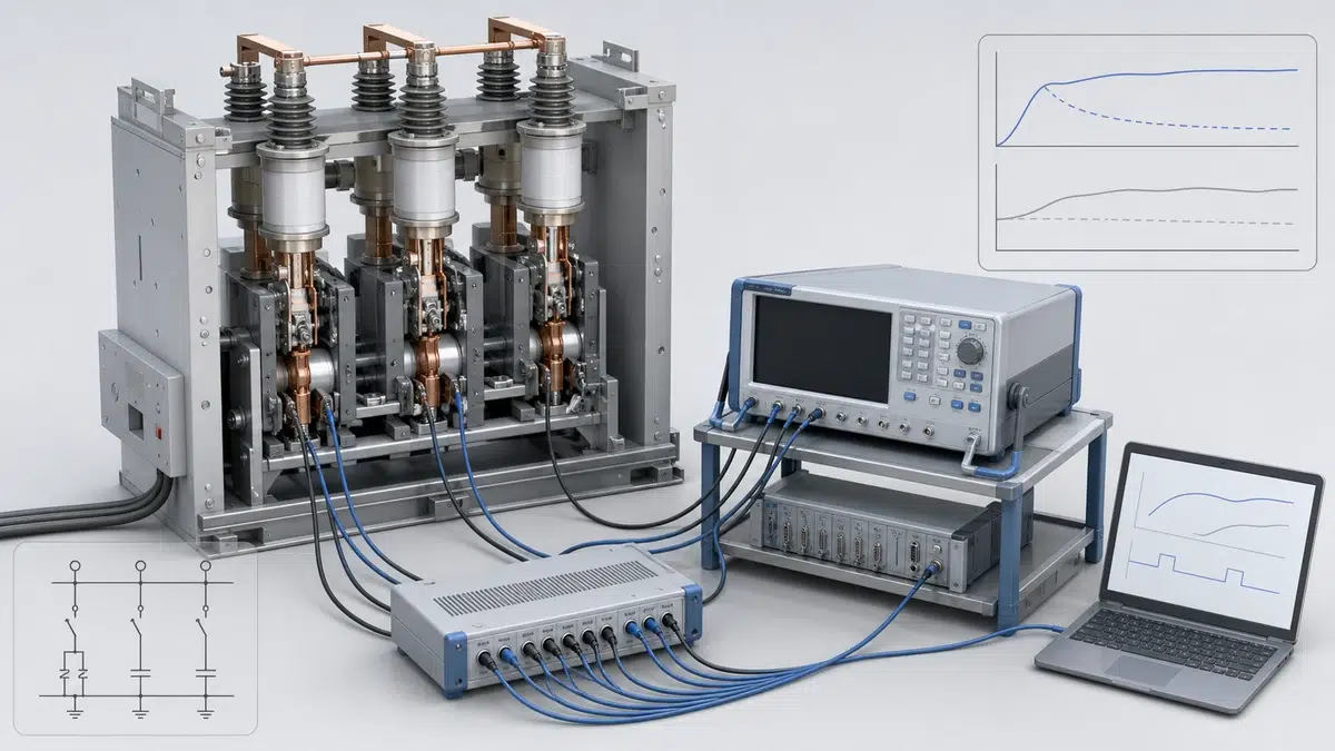
O ensaio de tempo de fechamento e abertura do VCB não é apenas uma verificação de tempo com resultado aprovado ou reprovado. Em um disjuntor a vácuo, é um método de avaliação de condição que registra o comportamento do mecanismo de operação, circuito de controle, contatos auxiliares, bobinas, sistema de trava e contatos principais durante as operações de fechamento e abertura. O resultado mais útil não é um número isolado, mas uma linha de base repetível que possa ser comparada aos requisitos do fabricante para aquele disjuntor e ao histórico de manutenção dele.
Isso importa porque os valores de tempo do VCB são específicos do produto. Por exemplo, os dados técnicos do disjuntor a vácuo Siemens 3AE8 incluem tempo de fechamento, tempo de arco, duração do repique dos contatos e valores de falta de simultaneidade no fechamento/abertura para essa família de produtos. Esses valores não devem ser tratados como limites universais para todos os projetos de VCB. A interpretação correta é comparar o resultado medido com o manual aplicável do disjuntor, os dados da placa de identificação, o regime de ensaio e os registros anteriores, e não com uma regra genérica de tempo.
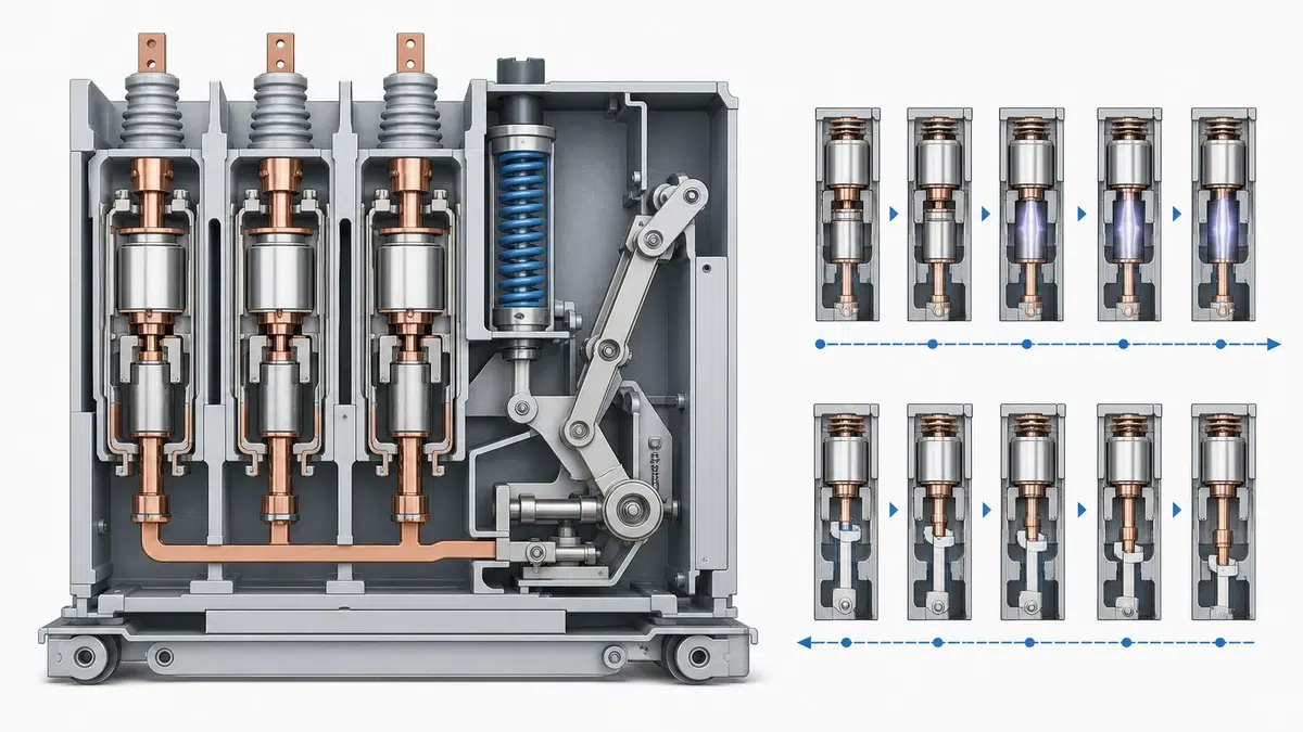
A linha de base do ensaio de tempo de fechamento e abertura deve ser registrada quando se sabe que o disjuntor está em boas condições mecânicas e elétricas: após o comissionamento, uma revisão geral ou uma manutenção corretiva que tenha restabelecido a operação adequada. Essa linha de base passa a ser a referência para ensaios futuros.
Uma linha de base prática normalmente registra:
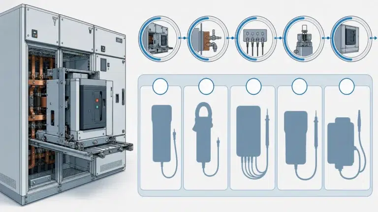
A linha de base também deve registrar as condições do ensaio. A fonte da tensão de controle, a condição de carregamento do disjuntor, sua posição, as condições ambientais, a disposição dos cabos de ensaio e a configuração do analisador de tempo podem afetar a repetibilidade. Se os ensaios futuros não forem realizados de modo comparável, o desvio aparente pode ser parcialmente procedimental, e não mecânico.
A interpretação mais sólida do tempo começa pela documentação aplicável ao VCB. A documentação Siemens 3AE8 mostra por quê: ela define valores de tempo de fechamento, tempo de arco, duração do repique e falta de simultaneidade no fechamento/abertura para esse produto, mas não estabelece uma tabela universal de tempos para todos os disjuntores a vácuo. A fonte principal do requisito específico do produto indicado aqui é os dados técnicos do VCB Siemens 3AE8 Para equipamentos e opções de configuração, compare o regime do projeto com as opções de disjuntores a vácuo.
Para as equipes de manutenção, isso significa que o tempo medido de fechamento ou abertura deve ser avaliado em relação aos requisitos publicados para o disjuntor específico, quando disponíveis. Se a instalação usar várias famílias de VCB, o modelo do analisador de tempo não deve reutilizar automaticamente os limites de um modelo para outro.
O mesmo princípio vale para sequências de operação. As perguntas frequentes da Schneider sobre a IEC 62271-100 identificam a sequência O-0.3s-CO-15s-CO para determinados ensaios de interrupção de curto-circuito, estabelecimento e resistência mecânica. Essa sequência é importante no contexto correto de norma e regime, mas sua aplicabilidade deve ser confirmada para o disjuntor, sua classificação e o objetivo do ensaio.
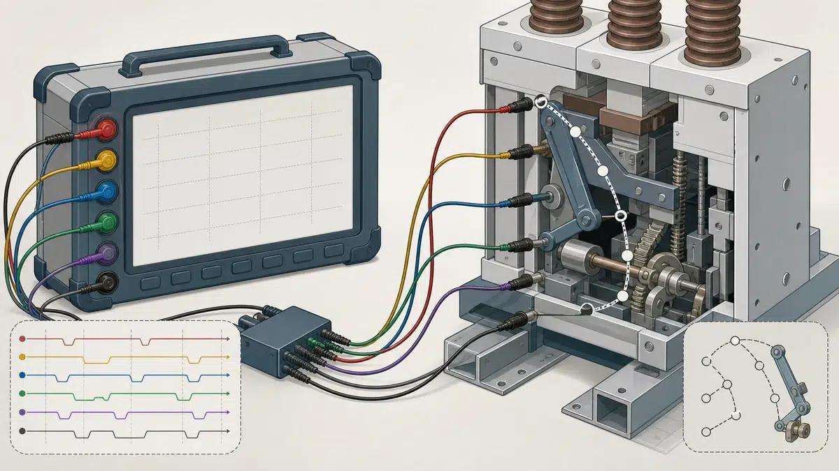
A melhor forma de interpretar o desvio do mecanismo é considerá-lo uma mudança na assinatura operacional do disjuntor ao longo do tempo. Uma única operação de fechamento ou abertura pode ser afetada pelo estado de carregamento, condição da lubrificação, estabilidade da tensão de controle, configuração do ensaio ou inatividade recente. Resultados repetidos e comparação de tendências são mais confiáveis.
Entre as preocupações comuns com o padrão de tempo estão:
Essas mudanças não identificam automaticamente uma única peça defeituosa. Elas indicam onde a investigação deve começar. Por exemplo, um tempo de abertura maior pode justificar a verificação da bobina de disparo, liberação da trava, pontos de atrito mecânico, fiação de controle e intertravamentos auxiliares. Um tempo de fechamento maior pode apontar para a bobina de fechamento, mecanismo de energia armazenada, condição das articulações, sistema de carregamento ou comportamento da alimentação de controle. Se o comando ou o resultado do mecanismo for anormal, prossiga com o guia de diagnóstico de falhas operacionais do VCB.
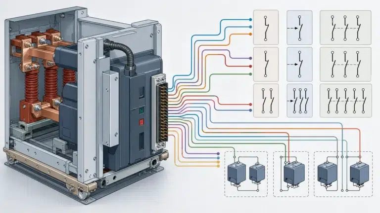
Os resultados de tempo ganham significado quando associados às verificações de controle e do mecanismo. A lista de manutenção SecoVac da ABB prevê testar chaves auxiliares e de posição durante operações de abertura/fechamento e verificar as bobinas de fechamento, disparo e trava. Isso apoia uma interpretação baseada na condição: o desvio de tempo deve ser analisado junto aos dispositivos que iniciam, comprovam e controlam o movimento.
Um VCB pode aparentar um problema de tempo quando a causa real está no circuito de controle. Alguns exemplos são energização fraca da bobina, retorno atrasado do contato auxiliar, indicação de posição inconsistente ou comportamento da bobina de trava que não corresponde à sequência esperada. Por outro lado, o circuito de controle pode funcionar corretamente enquanto as articulações mecânicas, o sistema de carregamento das molas ou as superfícies da trava provocam movimento mais lento ou menos sincronizado.
Por esse motivo, o ensaio de tempo de fechamento e abertura do VCB não deve ser tratado como registro independente. Ele deve ser associado às verificações operacionais, das bobinas e das chaves, bem como às observações de manutenção documentadas.
A resistência dos contatos fechados é uma medição diferente do tempo de fechamento/abertura. A orientação de manutenção Siemens SDV7 exige registrar essa resistência a cada intervalo de manutenção para monitorar a condição, identificando separadamente as verificações do mecanismo e do controle elétrico. Essa separação é útil: uma resistência baixa e estável não prova que o disjuntor abre rapidamente, e um tempo aceitável não comprova a integridade do caminho de corrente fechado. Confira os dados do regime e da placa de identificação com o guia de classificação e seleção de VCB antes da aceitação.
Portanto, um registro prático de manutenção deve manter os resultados de tempo e resistência juntos no mesmo arquivo histórico, mas interpretá-los separadamente. Se o tempo estiver desviando e a resistência permanecer estável, o problema pode ser mais mecânico ou relacionado ao controle. Se a resistência aumentar enquanto o tempo permanece estável, a questão pode estar mais relacionada à condição dos contatos, das conexões ou à integridade do caminho de corrente. Se ambos mudarem, o disjuntor merece investigação mais cuidadosa antes de retornar a um serviço crítico.
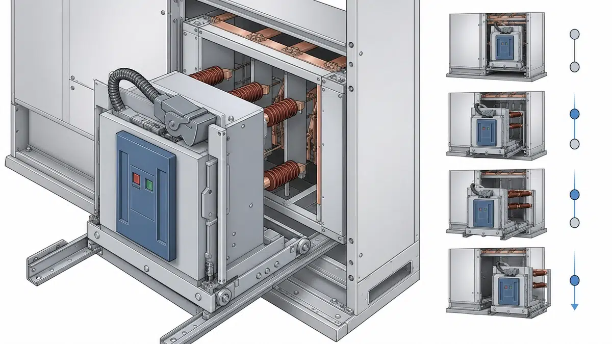
Um registro de ensaio defensável deve ser repetível. O objetivo é reduzir a incerteza antes de decidir se a mudança de tempo é real. Se a primeira operação após um longo período inativo diferir das posteriores, o registro deve informar isso, sem ocultar a diferença. Se a fonte de tensão de controle mudar entre ensaios, essa alteração também deve ser registrada. Se o disjuntor acabou de ser lubrificado, ajustado, limpo ou reparado, esse evento deve ser vinculado ao resultado de tempo. A lista de verificação de aceitação de fábrica e em campo do VCB oferece uma estrutura complementar para critérios de aceitação, resultados e registros de encerramento.
Bons registros incluem:
Isso cria um histórico de manutenção mais útil do que um certificado único. A equipe pode verificar se o disjuntor está estável, melhorando após o serviço ou desviando em direção a um problema funcional.
O ensaio de tempo de fechamento e abertura do VCB mede a relação temporal entre o comando elétrico e o movimento físico dos contatos do VCB durante o fechamento e a abertura. Conforme o equipamento de ensaio e o projeto do disjuntor, também pode registrar a dispersão entre polos, o repique dos contatos, o tempo dos contatos auxiliares e o comportamento da corrente das bobinas. O resultado serve para comparar o disjuntor com os requisitos específicos do produto e com sua própria linha de base de manutenção.
É o registro de referência feito quando o VCB está em uma condição aceitável conhecida. Ele deve conter detalhes suficientes para comparações futuras, incluindo tempos de fechamento e abertura, dispersão entre polos, comportamento relevante dos contatos auxiliares e condições do ensaio. A linha de base é especialmente valiosa porque os limites do fabricante são específicos do produto, e a tendência histórica do próprio disjuntor muitas vezes revela desvios antes de uma simples avaliação de aprovado/reprovado.
É uma mudança gradual no comportamento operacional do VCB ao longo do tempo. Pode aparecer como fechamento ou abertura mais lentos, maior dispersão entre polos, aumento do repique, mudança no comportamento da corrente da bobina ou tempo inconsistente das chaves auxiliares. O desvio deve ser interpretado com evidências de manutenção, e não estimado por um único número, pois a causa pode envolver o mecanismo de operação, sistema de trava, bobinas, circuito de controle, chaves ou condições de ensaio.
As chaves auxiliares e de posição ajudam a confirmar se a sequência de controle e indicação corresponde ao movimento dos contatos principais. A lista de manutenção SecoVac da ABB apoia essa abordagem ao exigir testes dessas chaves durante operações de abertura/fechamento e incluir verificações das bobinas de fechamento, disparo e trava. Se o retorno auxiliar mudar de forma tardia, antecipada ou inconsistente, o registro de tempo deve ser analisado junto à condição da chave e do circuito de controle.
A sequência O-0.3s-CO-15s-CO é indicada nas perguntas frequentes da Schneider sobre a IEC 62271-100 para determinados ensaios de interrupção de curto-circuito, estabelecimento e resistência mecânica. Ela não deve ser aplicada indiscriminadamente a toda verificação de tempo em campo. O uso correto depende do disjuntor, da norma, da classificação, do regime e do objetivo do ensaio. Antes de usar qualquer sequência operacional como base de aceitação, confirme sua aplicabilidade ao VCB específico e ao requisito de manutenção ou ensaio.
O tempo avalia o movimento e a sequência operacional. A resistência dos contatos fechados avalia a condição do caminho de corrente fechado. A orientação de manutenção Siemens SDV7 exige registrar essa resistência em cada intervalo de manutenção e identificar separadamente as verificações do mecanismo e do controle elétrico. Ambos os registros são importantes, mas um não substitui o outro.
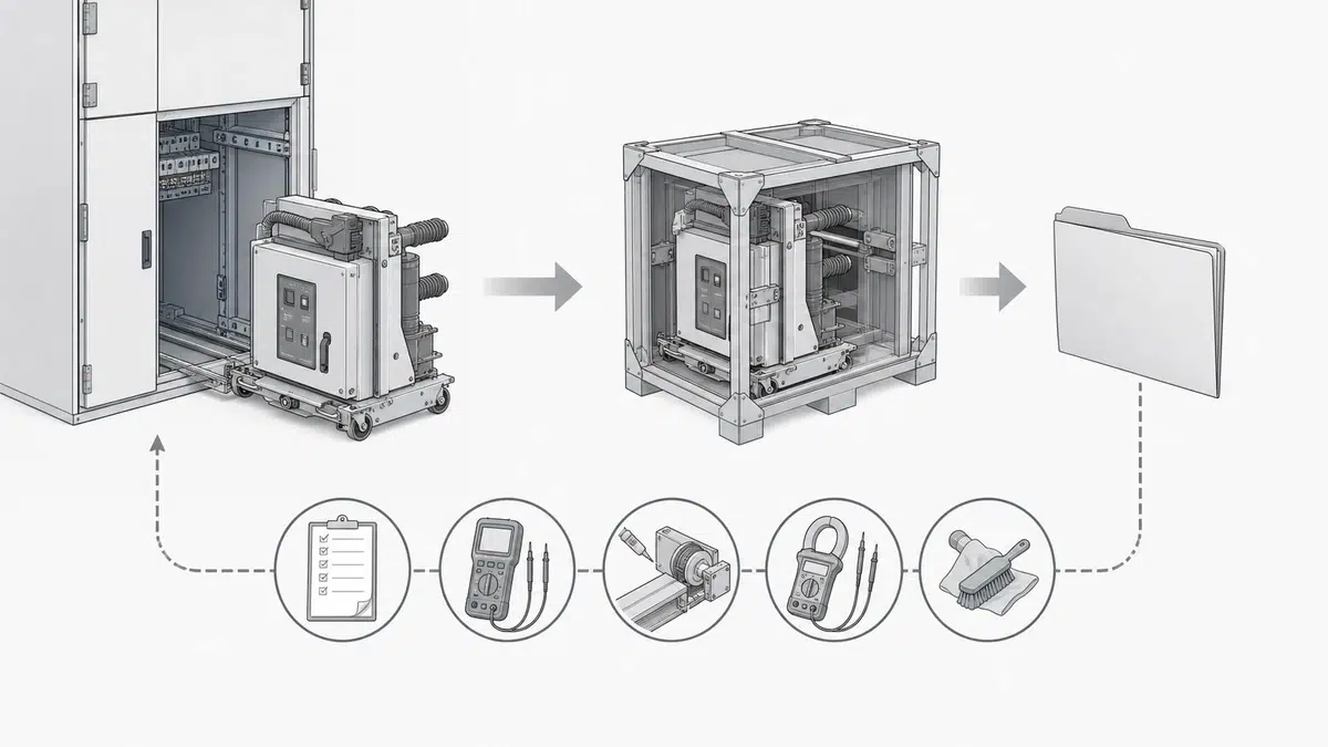
Um fluxo prático começa pela confirmação dos requisitos aplicáveis do fabricante e pelo registro ou recuperação da linha de base do próprio disjuntor. Em seguida, realiza-se o ensaio de tempo de fechamento/abertura em condições controladas e documentadas. Compara-se o resultado com o requisito específico do produto e com os registros anteriores. Se houver desvio, revisam-se as chaves auxiliares, indicação de posição, bobinas de fechamento, disparo e trava, alimentação de controle, mecanismo de operação e registros de resistência dos contatos fechados antes de atribuir uma causa.
A conclusão mais confiável normalmente se baseia na tendência: é mais fácil justificar a continuidade do serviço de um VCB que permanece consistente com sua linha de base e documentação do produto; já um disjuntor com desvio repetido de tempo merece inspeção direcionada, mesmo que uma leitura isolada ainda pareça próxima do limite de aceitação.