Precisa das especificações completas?
Faça o download do nosso Catálogo de Produtos 2025 para obter desenhos detalhados e parâmetros técnicos de todos os componentes do quadro elétrico.
Obter catálogo
Faça o download do nosso Catálogo de Produtos 2025 para obter desenhos detalhados e parâmetros técnicos de todos os componentes do quadro elétrico.
Obter catálogo Faça o download do nosso Catálogo de Produtos 2025 para obter desenhos detalhados e parâmetros técnicos de todos os componentes do quadro elétrico.
Obter catálogo
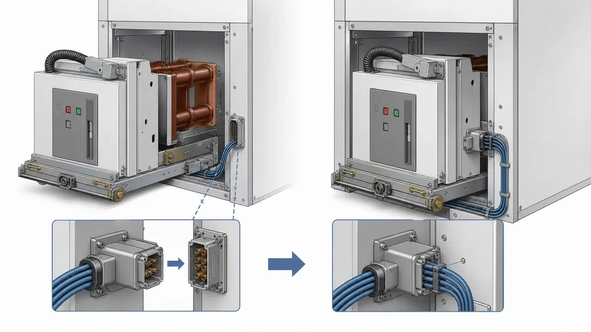
Withdrawable VCB secondary plug failures can turn a mechanically healthy vacuum circuit breaker into equipment that will not close, will not trip from remote control, gives false position indications, or fails interlock logic. In a withdrawable VCB, the primary power circuit is not the only connection that matters. The breaker also depends on a secondary control interface between the moving breaker truck and the fixed panel or cradle.
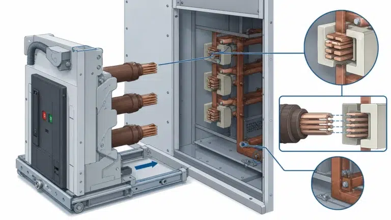
That interface may be a manual multi-pole control wiring plug connector, or it may be an automatic secondary disconnect that mates as the breaker reaches the connected position. The exact design depends on the VCB and switchgear family. ABB guidance for a withdrawable assembly describes a multi-pole control wiring plug connector between the panel and the circuit breaker and states that the plug and socket must be connected before racking the breaker to the service position. Schneider guidance for EvoPacT MV equipment describes a secondary disconnect that normally connects automatically at the connected position and disconnects while racking out toward test or disconnected, with a movable position that can permit testing in the test/disconnected position.
Because this connector carries control, indication, protection, and auxiliary circuits rather than load current, failures are often misread as relay faults, coil faults, auxiliary switch faults, or operator error. A disciplined diagnosis separates the secondary plug problem from the rest of the VCB control circuit.
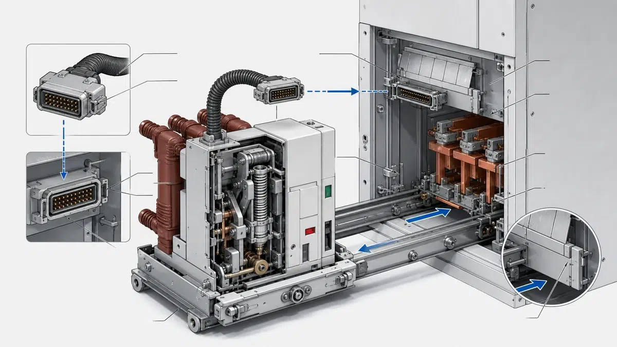
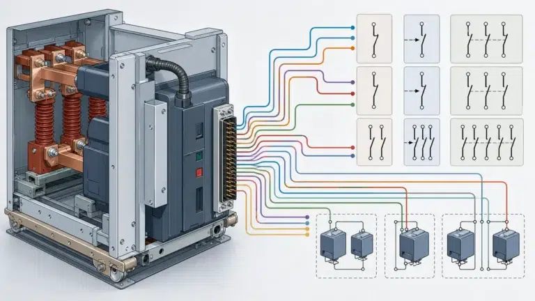
The secondary plug is the removable control-circuit bridge between the fixed switchgear and the withdrawable VCB. It may carry circuits associated with closing, tripping, spring charging, anti-pumping, auxiliary contacts, position indication, lockout, and protection or monitoring signals, depending on the equipment design. Review the medium-voltage VCB product range as a practical starting point for matching the required breaker format to the application.
In a manual plug arrangement, the plug and socket must be correctly engaged before the breaker is moved into its service position. In an automatic secondary disconnect arrangement, the contacts are designed to mate during racking into the connected position and separate when the breaker is racked out toward test or disconnected. Some designs allow the secondary disconnect to be moved or positioned for testing while the breaker remains in test/disconnected position.
This distinction matters during troubleshooting. A failure on a manually connected plug can be caused by the plug never being seated. A failure on an automatic disconnect can be caused by racking position, contact travel, alignment, or damage in the cradle interface.
The most common symptoms are control symptoms, not primary circuit symptoms. Operators may see the breaker physically rack normally, yet the control scheme behaves as if part of the breaker is missing.
Typical indications include:
These symptoms do not prove that the secondary plug is the root cause. They show that the secondary interface should be inspected before replacing coils, relays, motors, or auxiliary switches.
Withdrawable VCB secondary plug failures usually come from loss of continuity, incomplete mating, or mechanical damage at the breaker-to-panel interface. The safest approach is to stay within the manufacturer’s maintenance instructions and not apply generic dimensions, torque values, contact pressure values, or pin assignments unless the original documentation provides them. The ABB ZN1 vacuum circuit breaker manual is the primary source for the product-specific requirement stated here.
Likely causes include:
Schneider guidance specifically identifies breaker-to-cradle misalignment as a potential source of secondary disconnect plug and receptacle damage. It also states that inspection and maintenance are governed by the manufacturer-supplied parts and instructions. That point is important: the fix is not to bend contacts until they “look right,” but to restore the interface according to the equipment documentation. The VCB rated-data reference helps translate the system duty into the breaker data that must be confirmed.
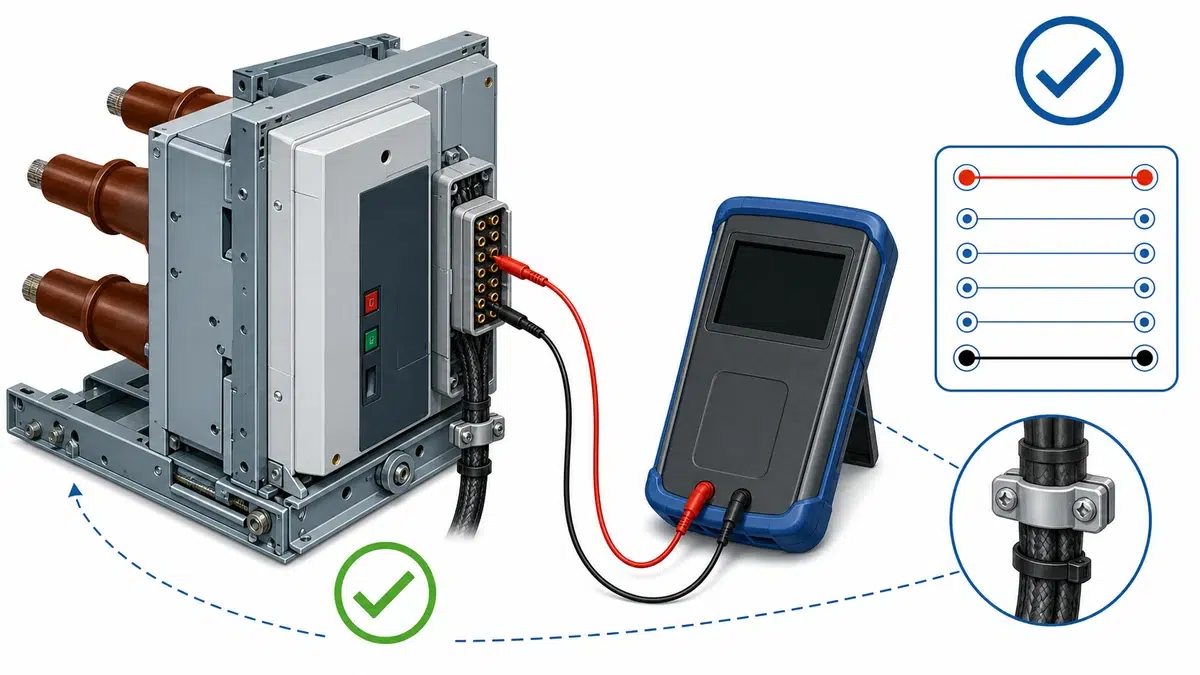
Before any inspection or test, follow the site safety procedure, isolate energy sources as required, and use qualified personnel. A VCB control circuit may include stored energy, external control power, trip circuits, closing circuits, and interlocks. Treat the secondary plug as part of the protection and control system, not as a harmless accessory.
A practical diagnostic sequence is:
1. Confirm the symptom and operating position: disconnected, test, connected, or service.
2. Verify whether the VCB design uses a manual plug or an automatic secondary disconnect.
3. Check that the breaker is in the position required by the manufacturer for the control function being tested.
4. Inspect the plug, socket, disconnect block, guides, latch points, mounting hardware, and visible wiring.
5. Look for misalignment marks, scraped plastic, bent guide surfaces, broken receptacle support, or unusual racking resistance.
6. Compare the breaker and cradle identification to confirm compatibility.
7. Test continuity only against the correct control drawing and only under the required isolation conditions.
8. Re-test operation in the correct position after any approved cleaning, adjustment, or replacement.
This sequence prevents unnecessary replacement of close coils, trip coils, relays, or auxiliary switches when the actual fault is a disconnected or damaged secondary interface.
For withdrawable VCBs that use a manual multi-pole control wiring plug, the first check is simple but critical: confirm whether the plug and socket are connected before the breaker is racked to the service position. ABB guidance for the referenced withdrawable assembly states this requirement directly.
A manual plug failure can occur when the operator assumes the plug connects automatically, when the plug is left hanging after maintenance, or when the plug appears inserted but is not fully seated. The visible condition of the connector should be checked before racking, not after a failed closing attempt.
Inspection should include:
If the plug does not seat normally, do not force it. Forcing can turn a simple seating issue into damaged contacts, broken insulation, or a misaligned receptacle.
For a VCB with an automatic secondary disconnect, the connector should mate as the breaker reaches the connected position. For EvoPacT MV equipment, Schneider guidance states that the secondary disconnect normally connects automatically at the connected position and disconnects while racking out toward test/disconnected. It can also be moved to permit testing in the test/disconnected position.
That means position is part of the diagnosis. If the breaker is not fully in the connected position, the secondary circuits may not be connected as expected. If the disconnect has been moved for test-position work, its position should be verified before drawing conclusions about a fault.
Checks should include:
A repeat failure after breaker insertion is a warning sign. The root cause may be the cradle interface, not the removable breaker alone.
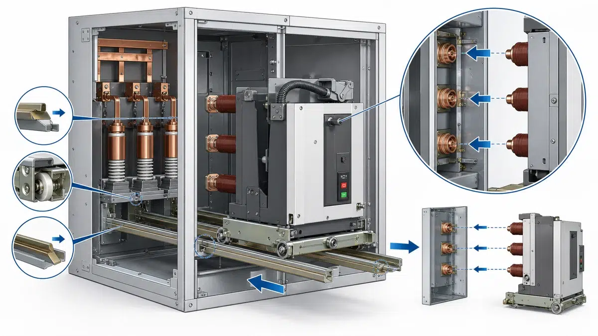
Misalignment is one of the most important mechanical causes of withdrawable VCB secondary plug failures. If the breaker truck does not approach the cradle correctly, the secondary contacts may not enter squarely. This can bend pins, distort sockets, crack insulating supports, or push a receptacle out of position.
Misalignment may be caused by worn guide parts, damaged cradle components, obstruction in the racking path, incorrect handling, or a breaker that is not suitable for that cradle. The symptom may appear electrical, but the failure mechanism is mechanical.
Warning signs include:
When misalignment is suspected, replacing only the plug may not fix the problem. The cradle, breaker truck, guides, secondary disconnect mounting, and manufacturer-specified alignment checks should be addressed together.
The correct fix depends on the failure mode. The goal is to restore the designed interface, not to improvise a connection.
Practical corrective actions include:
Avoid shortcuts such as wedging the plug, bypassing interlocks, bending contacts without guidance, or tying circuits together to “prove” the breaker works. These actions can mask the real fault and may compromise trip, close, indication, or protection functions. If a command or mechanism result is abnormal, continue with the VCB close/trip fault checklist.
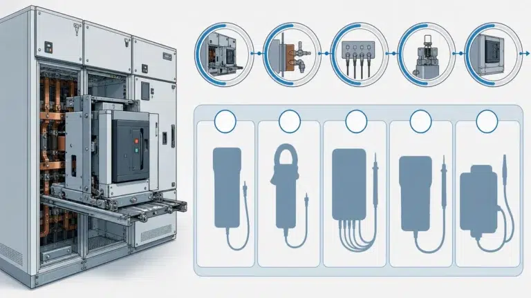
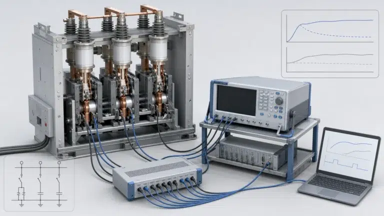
After corrective work, the VCB should be tested in the positions relevant to the equipment design. A repair is incomplete if the plug looks good but the control functions are not proven through normal operation. Use the VCB FAT and SAT acceptance checklist to keep factory and site evidence traceable through handover.
Useful post-repair checks include:
The acceptance criteria should come from the VCB manual, switchgear manual, drawings, and site procedure. Do not substitute generic acceptance values for manufacturer requirements.
A withdrawable VCB secondary plug failure is a loss, degradation, or incorrect engagement of the control wiring connection between the withdrawable vacuum circuit breaker and the fixed panel or cradle. It can affect closing, tripping, indication, interlocking, spring charging signals, or protection-related feedback even when the primary circuit and vacuum interrupters are not the source of the problem.
A manual plug must be physically connected according to the equipment instructions, such as the ABB withdrawable assembly guidance that requires the plug and socket to be connected before racking to service position. An automatic secondary disconnect is designed to connect as the breaker reaches the connected position and disconnect as it is racked out, as described for EvoPacT MV equipment. Some automatic designs also allow a test-position arrangement for control testing.
The fastest reliable method is to match the symptom to the breaker position, connector type, and control drawing, then inspect the secondary interface before replacing control components. If the breaker fails only after racking, gives inconsistent indication, or behaves differently in test and connected positions, the secondary plug or disconnect should be checked early.
Breaker-to-cradle misalignment can prevent proper secondary contact engagement and can physically damage the plug and receptacle. Schneider guidance identifies misalignment as a potential source of secondary disconnect plug and receptacle damage. If damage repeats after parts replacement, the cradle and breaker alignment should be investigated before the VCB is returned to service.
The safest fix is to follow the manufacturer’s inspection and maintenance instructions, use the correct supplied parts, and correct any underlying alignment or racking problem. Damaged contacts, cracked housings, loose receptacles, or distorted guides should not be forced back into service without confirming the approved repair method and functional performance.