Request a Quote for High-Voltage Components&Equipment

Tell us your requirements — rated voltage, model, quantity, and destination — and our XBR Electric team will prepare a detailed quotation within 24 hours.
Contact Form Demo
MV switchgear safety interlocks showing five-prevention logic with DSN lock and DXN voltage indicator

Safety Interlocks & Five-Prevention Logic (DSN/DXN) in MV Switchgear

What “Safety Interlocks” and “Five-Prevention” mean in MV switchgear

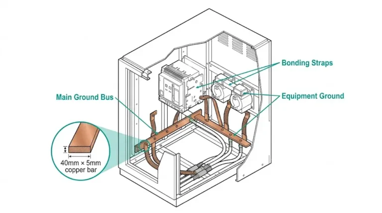
A safety interlock in medium-voltage (MV) switchgear is an engineered permission barrier: it prevents an unsafe operation sequence from being physically possible (mechanical interlock) or electrically permitted (control-circuit interlock). The goal is not convenience—it is to make dangerous sequences impossible, especially during outage work when people are under time pressure.

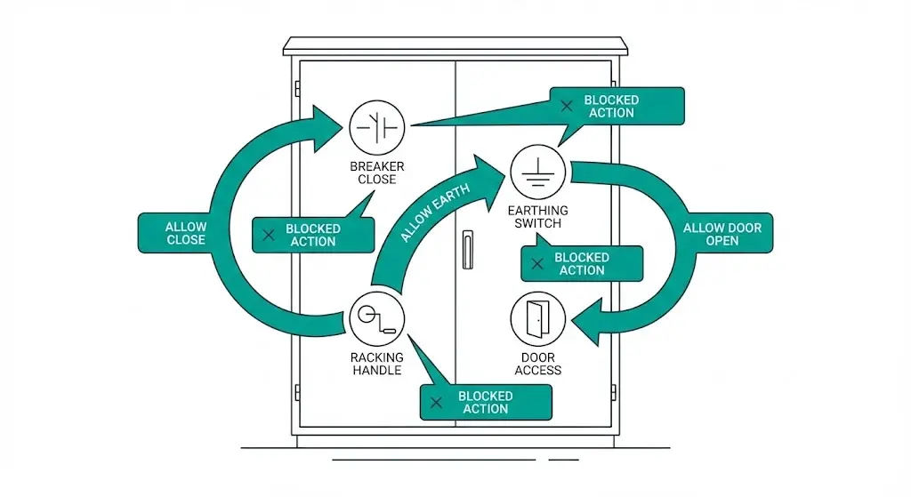
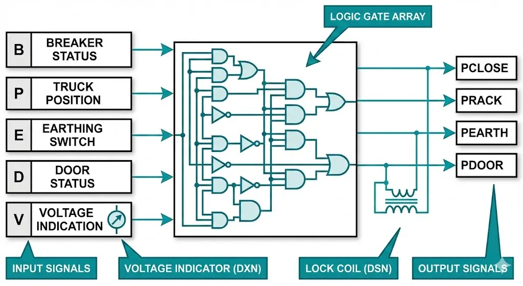
“Five-prevention” (5-prevention) is the practical framework used in many metal-enclosed lineups: it defines the specific misoperations that must be blocked, then ties each block to verifiable equipment states (breaker status, truck position, earthing status, door/access status).

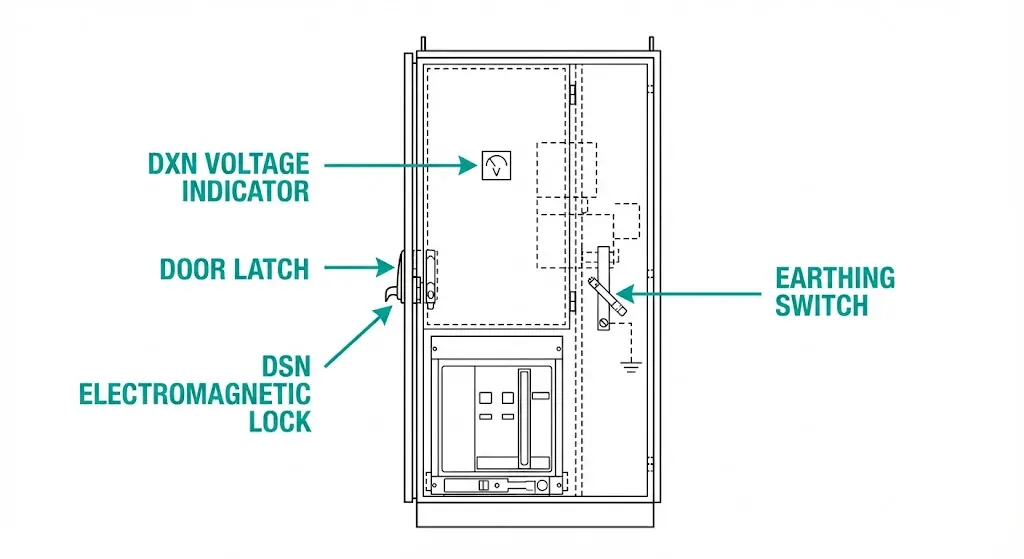
You will often see labels like DSN and DXN in drawings and site conventions. These names are not universal and should be read directly from the project schematics, but common usage is:

  • DSN: an electromagnetic lock/solenoid that enforces sequencing (a “permission actuator” in the interlock chain).
  • DXN: a voltage presence indication element that supports “LIVE / NOT LIVE / UNKNOWN” decisions (a “status confirmer,” not a standalone safety proof).

Most MV panels fall in typical voltage classes such as 12 kV up to 40.5 kV, while the interlock and indication circuits commonly run on 110 V DC or 220 V AC/DC control power (often 50/60 Hz for AC). Your interlock philosophy should be conservative: missing signals or conflicting feedback must default to NOT permitted for high-consequence actions (earthing, door access, racking, closing).

For standards context, the IEC 62271 family covers high-voltage switchgear and controlgear; IEC 62271-200 addresses AC metal-enclosed switchgear and controlgear. Authority reference: IEC 62271 series (IEC Webstore).Internal reference (non-competing context): Switchgear Component Manufacturer.
Diagram of interlock boundary in MV switchgear with breaker truck, earthing switch, door latch, DSN lock, and DXN indicator
Block-level interlock boundary tying breaker status, truck position, earthing state, and door access into one enforced sequence.

The “five misoperations” checklist and the human actions it blocks

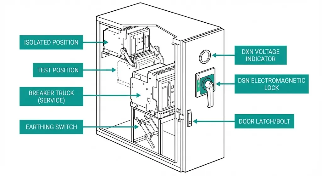
Five-prevention only works when it is written as “you cannot do X unless state Y is proven.” Below is a practical checklist that can be used as an operations/commissioning reference across different MV lineups.

  1. Close breaker while earthing switch is CLOSED → direct fault-to-earth path, severe arc risk → Block closing until earthing is proven OPEN and the breaker/truck state is correct.
  2. Close earthing switch while breaker is CLOSED → earthing into an energized circuit → Block earthing until breaker OPEN is proven and position conditions are satisfied.
  3. Rack a withdrawable breaker in/out while breaker is CLOSED → damage/arcing at primary stabs during motion → Block racking unless breaker OPEN and the mechanism is in the safe condition for movement.
  4. Open a door or access shutter when the primary circuit is not in a safe isolated/earthed state → exposure to live parts / arc hazard → Block access until the lineup reaches the defined “safe access state.”
  5. Act on false-safe indication (lost VT, miswired aux, failed indicator) → wrong decisions under pressure → Design for cross-checks and fail to “NOT permitted” when safety cannot be proven.
Internal reference (earthing mechanism context): Indoor HV Earthing Switches.
Five-prevention map showing blocked actions and permissives in MV switchgear safety interlocks
Five-prevention map linking common misoperations to the specific interlocks that block them.

[Expert Insight]

  • Treat UNKNOWN as a real state: if the panel cannot prove isolation, block the risky action.
  • The easiest way to “break” five-prevention is a small maintenance change: swapped NO/NC contacts or a forgotten jumper.
  • If the safe path is slow and confusing, operators will invent shortcuts—make the permitted sequence obvious.

DSN/DXN interlock logic: signals, states, and permissive chains

A robust interlock scheme is a state machine. DSN (lock coil) is typically an output device that physically prevents a handle/door/operation; DXN (voltage indication) is typically an input that informs whether “live” might still exist. Neither should be treated as a single point of truth.

Use a defined set of inputs (states) and outputs (permissives), and then validate them during commissioning with “wrong action” attempts. Typical inputs:

  • Breaker status (OPEN/CLOSED via aux contacts + mechanical indication)
  • Truck position (SERVICE/TEST/ISOLATED via position switches + indicator)
  • Earthing switch (OPEN/CLOSED)
  • Door/access status (CLOSED/OPEN)
  • Voltage indication (LIVE/NOT LIVE/UNKNOWN)

Typical outputs:

  • PCLOSE (allow close)
  • PRACK (allow rack-in/out)
  • PEARTH (allow earthing operation)
  • PDOOR (allow door open)

A readable matrix (example) shows how the panel should behave:

  • B=OPEN, P=TEST, E=OPEN, D=CLOSED, V=UNKNOWN → PRACK=YES; PCLOSE=NO; PDOOR=NO; PEARTH=YES*
  • B=OPEN, P=ISOLATED, E=OPEN, D=CLOSED, V=NOT LIVE → PRACK=YES; PCLOSE=NO; PDOOR=YES*; PEARTH=YES
  • B=OPEN, P=ISOLATED, E=CLOSED, D=CLOSED → PRACK=NO; PCLOSE=NO; PDOOR=YES (access allowed only per defined scheme); PEARTH=NO
  • B=CLOSED (any position) → PRACK=NO; PEARTH=NO; PDOOR=NO

*Many lineups add extra requirements such as key release, shutter position, or latch engagement before PEARTH/PDOOR becomes YES.

The rule to protect people is consistent: for high-consequence operations, missing input = NOT permitted and disagreement = NOT permitted, even if that creates nuisance blocks that must be resolved by proper sensing and wiring discipline.

DSN/DXN permissive chain diagram showing input states and output interlocks for MV switchgear
Permissive-chain model showing how DSN (lock) and DXN (voltage indication) integrate into interlock decisions.

Hardware building blocks: mechanical key interlocks vs electrical interlocks

Five-prevention is enforced by hardware. A scheme is only as safe as its weakest enforcement point.

Mechanical key interlocks (trapped key / key exchange / linkage)
Best at creating a hard, power-independent barrier for access and earthing. They physically prevent motion of door bolts, earthing handles, or racking handles. Typical issues are wear and alignment: sticky cylinders, bent cams, door sag, or poor key control.

Electrical interlocks (aux contacts, position switches, relays, DSN-type locks)
Best at combining multiple states and supporting remote operation. They can also create evidence (alarms/logs). Typical issues are maintenance drift: miswired aux contacts, swapped NO/NC logic, stuck relays, or permissives that go true when a signal is missing.

Practical comparison (what engineers should care about):

  • Power dependency: Mechanical = none; Electrical = depends on control supply (commonly 110 V DC or 220 V AC/DC).
  • Fail behavior target: Mechanical often fails “blocked” if intact; Electrical must be designed to fail “NOT permitted” on signal loss.
  • Bypass risk: Mechanical relies on key discipline; Electrical relies on wiring discipline and tamper control.
  • Best use: Mechanical for door/earthing/racking enforcement; Electrical for close permissives and state correlation.

[Expert Insight]

  • If a lock can be defeated with one jumper, assume it will be—design tamper evidence and audit points.
  • Mechanical alignment matters: a few millimeters of sag can turn a safe lock into a nuisance block or a defeated block.
  • “Indicators agree” is not a test. A state matrix plus misoperation attempts is.

Typical MV switchgear interlock sequences (breaker truck + earthing switch + door)

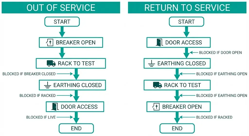
Operators follow sequences, so commissioning should verify that the lineup forces the safe sequence every time.

Sequence A — taking a feeder out of service (isolate + earth + access):

  1. Open/trip the breaker; verify OPEN by indicator and aux contact.
  2. Rack from SERVICE to TEST; racking must be blocked if the breaker is CLOSED.
  3. Confirm position indication and shutters behave consistently.
  4. Close the earthing switch; earthing must be blocked unless breaker OPEN and the truck position matches the scheme.
  5. Only then allow door access per the lineup’s safe-access definition.

Sequence B — returning to service (close only when safe):

  1. Door closed/secured (if required by the permissive chain).
  2. Open the earthing switch; closing must remain blocked if earthing is still CLOSED.
  3. Rack from TEST to SERVICE; prevent service entry on ambiguous position feedback.
  4. Final permissive check (position=SERVICE, earthing=OPEN, door status per scheme, control supply healthy).
  5. Close the breaker.

Common field failure points to actively look for:

  • Position/shutter misalignment producing a false state.
  • Earthing travel issues where indication suggests CLOSED but engagement is incomplete.
  • Aux contact inversion after maintenance (NO/NC swapped).
  • DSN-type lock coil energizes but does not mechanically restrain due to wear or loose mounting.
Flowchart of MV switchgear interlock sequence for taking out of service and returning to service
Two safe operating sequences demonstrating the enforced order of racking, earthing, access, and closing operations.

Commissioning & maintenance checks that keep interlocks trustworthy

Interlocks usually fail partially. Commissioning and periodic maintenance should treat five-prevention as a system with pass/fail outcomes.

Mechanical checks (control power OFF is fine):

  • Door lock: attempt access across SERVICE/TEST/ISOLATED. PASS only if access is possible only in the defined safe-access state.
  • Key interlock: confirm the exact key capture/release order. PASS only if the unsafe sequence cannot be completed.
  • Earthing mechanism: verify full travel and positive end-stops. PASS only if OPEN/CLOSED indication matches true mechanical position.
  • Racking: attempt racking with breaker CLOSED. PASS only if physically blocked every time.

Electrical checks (control power ON):

  • Verify control supply matches the schematic requirements (commonly 110 V DC or 220 V AC/DC; 50/60 Hz for AC). PASS if undervoltage or a missing input does not create a false permissive.
  • Validate that breaker aux contacts and position switches match the indications. PASS if disagreement forces NOT permitted.
  • Exercise the DSN-type lock: energize/de-energize and confirm reliable restraint.
  • Where DXN-type voltage indication is used: verify that “UNKNOWN” blocks high-risk actions.

Misoperation simulation (the test that matters):
Try the forbidden actions—close with earthing CLOSED; earth with breaker CLOSED; rack with breaker CLOSED; open door in unsafe states. PASS only if the lineup blocks them reliably and repeatably.

Operational discipline completes the system: any temporary bypass should be logged, tagged, time-limited, and followed by a full interlock re-test after restoration.

When to upgrade or retrofit the interlock scheme (and what to specify)

Retrofits make sense when your lineup’s “allowed actions” no longer match how the site operates: repeated near-misses, frequent nuisance blocks that drive bypass behavior, mixed-vendor replacements that break the original permissive chain, or adding remote operation without upgrading access/earthing enforcement.

Procurement/spec items (write them so they can be tested):

  • A “shall not be possible” list covering the five-prevention targets.
  • Required state inputs: breaker status, truck position, earthing status, door/access status, and voltage state if used (LIVE/NOT LIVE/UNKNOWN).
  • Required outputs: PCLOSE, PRACK, PEARTH, PDOOR.
  • Control supply compatibility (e.g., 110 V DC or 220 V AC/DC) and defined behavior under supply loss (safety-critical actions default to NOT permitted).
  • Defeat control: sealed terminals, labeled test points, tamper-evident covers, and a documented bypass procedure.

Acceptance tests (witnessed and recorded):

  • Truth-table trials across representative states (including “unknown” and disagreement cases).
  • Power-loss behavior: remove control supply and confirm no false permissive appears.
  • Repeatability: run the key sequences at least 3 full cycles with consistent results.

Share your single-line diagram and the interlock drawings. XBRELE can convert the DSN/DXN scheme into a testable permissive matrix, identify bypass-prone points, and return a commissioning checklist your operators can execute with confidence.

FAQ

1) Is “five-prevention” the same thing as a key interlock?
Not exactly; five-prevention is the safety logic target, while a key interlock is one hardware method used to enforce part of that logic.

2) Can voltage indication alone be used to permit earthing?
It may support decisions, but many schemes add position and breaker-status confirmations so one failed signal doesn’t create a false-safe condition.

3) Why do some lineups block operations even when the operator believes it’s safe?
Conservative logic will block when it cannot prove the required state; the fix is usually better state sensing, wiring discipline, or mechanical alignment—not removing the block.

4) What’s the quickest way to catch a dangerous interlock defect during commissioning?
Use a written permissive matrix and physically attempt the forbidden actions under controlled conditions.

5) Do remote-operated panels reduce the need for physical interlocks?
Remote operation reduces exposure, but access, earthing, and racking still need hard prevention against unsafe sequences.

6) What should a site do if an interlock must be bypassed temporarily?
Treat it as a controlled deviation: label it, record who applied it and why, set a removal time, and re-test the full interlock sequence after restoration.

Hannah Zhu marketing director of XBRELE
Hannah

Hannah is the Administrator and Technical Content Coordinator at XBRELE. She oversees website structure, product documentation, and blog content across MV/HV switchgear, vacuum breakers, contactors, interrupters, and transformers. Her focus is delivering clear, reliable, and engineer-friendly information to support global customers in making confident technical and procurement decisions.

Articles: 61