Need Full Specifications?
Download our 2025 Product Catalog for detailed drawings and technical parameters of all switchgear components.
Get CatalogDownload our 2025 Product Catalog for detailed drawings and technical parameters of all switchgear components.
Get CatalogDownload our 2025 Product Catalog for detailed drawings and technical parameters of all switchgear components.
Get Catalog
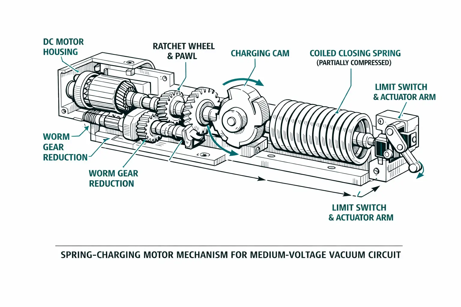

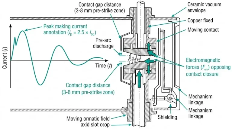
The charging cycle follows a precise mechanical sequence. When the motor energizes, a worm gear rotates a cam mechanism that progressively tensions the closing spring. Standard charging time runs 8–15 seconds for 12 kV vacuum circuit breakers. The motor continues until a limit switch detects full compression and interrupts motor current.
Three critical subsystems interact during this process:
Drive train components: Motor shaft, worm gear, charging cam, and roller followers transmit torque through the system. The gear train converts high-speed motor rotation (1,400–1,800 RPM) to approximately 2–4 RPM at the charging cam, multiplying torque by factors of 350:1 to 500:1.
Energy storage elements: The closing spring stores potential energy during charging. The opening spring typically charges during the closing operation itself, ensuring trip capability immediately after breaker closure.
Control and feedback devices: Limit switches, position indicators, and anti-pumping relays govern the charging sequence. The limit switch must reliably interrupt motor current at full charge—contact welding here causes motor burnout.
The closing spring stores potential energy according to the relationship E = ½kx², where k represents spring constant (typically 15–25 kN/m for 12kV breakers) and x is the compression distance (80–120 mm). This stored energy—generally 150–300 joules per spring—must overcome contact pressure, wipe distance, and mechanism friction during closing operations.
Field experience demonstrates that wear patterns in the worm gear assembly directly correlate with charging current anomalies. A healthy motor draws 2–4 amperes during mid-cycle operation. Worn gears or dried lubrication can increase current draw by 40–60%, signaling impending failure before complete mechanism seizure.
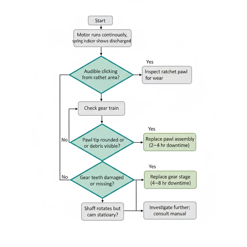
This failure mode presents a paradox: the motor operates normally, yet the spring never reaches full compression. The disconnect occurs somewhere in the mechanical transmission chain.
Symptom pattern: Motor energizes and runs continuously. Charging indicator remains in “discharged” position. Motor may eventually trip on thermal protection. Audible clicking from the ratchet area without corresponding spring movement.
| Root Cause | Field Indicators | Repair Action | Downtime |
|---|---|---|---|
| Ratchet pawl wear | Metallic debris near ratchet; rounded pawl tip | Replace pawl assembly; inspect ratchet wheel teeth | 2–4 hours |
| Gear train damage | Inconsistent motor sound; visible chipped teeth | Replace affected gear stage | 4–8 hours |
| Charging shaft key shear | Motor runs smoothly but cam doesn’t rotate | Replace shear key; investigate jam cause | 1–2 hours |
| Worm gear thread wear | Elevated motor current; slow charging progression | Replace worm gear set | 4–6 hours |
The ratchet-pawl interface deserves particular attention. The pawl transfers rotational energy from the motor-driven gear to the charging wheel. Contamination accelerates wear dramatically—grit particles embed in the hardened steel pawl tip and scoring begins. In dusty environments (cement plants, mining facilities), pawl life can decrease by 50% compared to clean indoor installations.
Gear train failures often start small. A single broken tooth creates impact loading on adjacent teeth, propagating damage through the train. Plastic intermediate gears—used in some cost-reduced designs—prove particularly vulnerable to thermal cycling between -25°C and +55°C operating ranges.
[Expert Insight: Ratchet Mechanism Diagnostics]
- Listen for distinct “click-click” without spring movement—indicates pawl skipping over teeth
- Check pawl spring tension; weak springs allow disengagement under load
- Inspect ratchet wheel for wear pattern asymmetry suggesting misalignment
- Verify charging cam key hasn’t partially sheared (motor rotates but cam slips)
When the charging motor fails to energize, troubleshooting splits between electrical supply issues and motor-internal faults. Systematic diagnosis prevents unnecessary motor replacement.
Symptom pattern: No motor rotation on command. Possible audible hum without shaft movement. Motor housing warm despite no operation. Control voltage present at panel terminals.
Limit switch malfunction ranks as the most common electrical cause. The charging limit switch serves dual purposes: stopping the motor at full charge and permitting restart after close operation. Contact welding—from interrupting inductive motor current—keeps the circuit permanently open. Mechanical linkage drift compounds the problem; bent actuator arms or worn cam followers prevent proper switch actuation.
Diagnostic step: Measure resistance across limit switch terminals with spring discharged. Open circuit indicates welded contacts or linkage misadjustment.
Motor winding failure manifests differently in DC versus AC designs. DC motors suffer brush wear and commutator degradation over 8,000–12,000 operations. AC motors face insulation breakdown, accelerated by moisture ingress in outdoor or high-humidity installations. Single-phase AC motors additionally depend on starting capacitors that degrade with age.
Diagnostic step: Measure winding resistance and compare to nameplate values; deviations exceeding ±10% indicate problems. Insulation resistance below 1 MΩ at 500V DC suggests moisture contamination. [VERIFY STANDARD: IEEE 43 provides specific insulation resistance criteria for rotating machinery testing]
Thermal protection lockout catches many technicians off-guard. Embedded thermal protection—bimetallic disc or PTC thermistor—prevents restart until the motor cools. Repeated partial charging attempts trigger protection before completing charge. The motor appears dead but simply requires a 15–30 minute cooling period.
For switchgear components operating in extreme environments, thermal protection settings may require adjustment or motor derating to prevent nuisance lockouts.
Charging times creeping upward signal developing problems that will eventually cause complete failure. Trending this parameter catches issues early.
Symptom pattern: Charging time exceeds 20 seconds (versus 8–15 second baseline). Motor current runs 20–40% above nameplate rating. Spring indicator barely reaches “charged” threshold. Close operation velocity decreases.
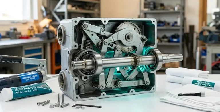
Lubricant degradation affects every moving interface in the mechanism. Greases specified for switchgear service maintain viscosity from -25°C to +70°C. But aged lubricant thickens—particularly in cold conditions. High-temperature exposure causes base oil separation, leaving stiff residue that impedes movement.
Field observations from northern climate installations show charging times can double during cold snaps when lubricant selection doesn’t match environmental conditions. Conversely, tropical installations see accelerated oxidation requiring more frequent relubrication.
Spring fatigue develops gradually over thousands of operations. Closing springs—typically chrome-silicon or chrome-vanadium steel—maintain consistent stored energy across their rated life of 8,000–10,000 mechanical operations. But approaching end-of-life, springs lose force capacity through stress relaxation. The motor works harder to achieve the same stored energy.
Measurement criteria: Compare spring free length to original specification. Permanent set exceeding 3% indicates replacement. Springs operating above 40°C ambient experience accelerated relaxation, reducing stored energy by 5–8% over a decade.
Bearing degradation throughout the mechanism accumulates wear incrementally. Pivot bearings at cam followers, main shaft, and lever connections develop excessive clearance. Bronze bushings exceeding 0.3mm radial play require replacement. Sealed ball bearings losing lubricant develop roughness detectable by manual rotation.

Intermittent failures frustrate troubleshooting because symptoms don’t reproduce consistently. These faults often trace to marginal conditions that only manifest under specific circumstances.
Symptom pattern: Motor starts and stops repeatedly during single charging cycle. “Charged” indication flickers. Anti-pumping relay activates unexpectedly. Breaker occasionally fails to close despite charged indication.
Limit switch adjustment drift develops gradually. The gap between switch actuator and operating cam determines switching precision. As cam surfaces wear or switch mounting loosens, this gap changes. Too tight: switch opens prematurely, before full charge. Too loose: switch never opens reliably, risking motor burnout.
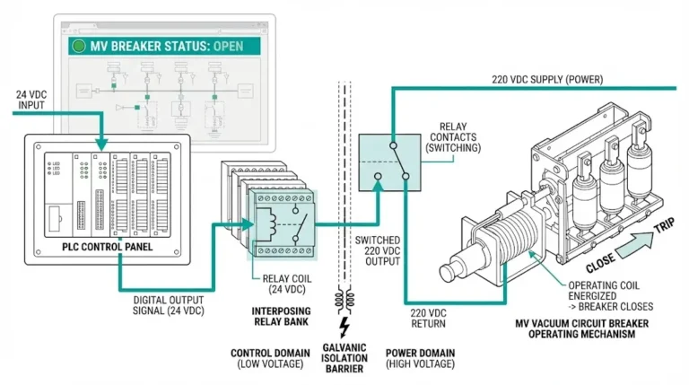
Control circuit voltage sag affects motor torque directly. A 110V DC motor receiving only 95V develops significantly reduced torque. During high-current charging phase, this voltage depression worsens. Battery banks approaching end-of-life exhibit this pattern—adequate voltage at rest, but sag under load.
Diagnostic protocol:
Loose connections cause localized voltage drops that static testing misses. Vibration from motor operation, thermal cycling, and age loosen terminals progressively. A connection measuring 0.1Ω resistance drops 0.4V at 4A charging current—enough to cause erratic behavior at marginal supply voltages.
[Expert Insight: Voltage Troubleshooting]
- DC systems: Check battery specific gravity and load-test capacity
- AC systems: Verify transformer tap settings match actual supply voltage
- Measure at motor terminals during operation, not at rest
- Suspect wiring if panel voltage normal but motor voltage low during charging
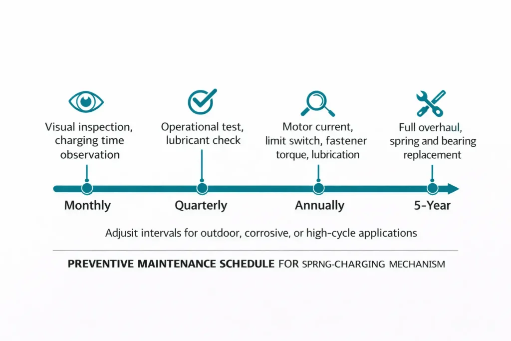
Reactive repair addresses immediate failures, but preventive maintenance extends mechanism life and prevents protection gaps. These intervals represent industry consensus for medium-voltage stored-energy breakers per IEC 62271-100 mechanical endurance requirements:
| Frequency | Inspection Tasks | Action Criteria |
|---|---|---|
| Monthly | Visual: spring indicator position, unusual sounds during charging | Investigate any deviation from normal |
| Quarterly | Operational: record charging time, verify close/open operations | Charging time >15% above baseline triggers investigation |
| Annually | Detailed: motor current measurement, limit switch inspection, fastener torque, lubrication condition | Relubricate per manufacturer schedule; tighten loose fasteners |
| 5-Year | Overhaul: complete disassembly, spring measurement, bearing replacement | Replace springs >5,000 operations or showing >3% set |
Environmental conditions modify these intervals. Outdoor switchgear, corrosive atmospheres, and high-cycling applications require compressed schedules. Equipment in clean indoor environments with infrequent operation may extend intervals—but never beyond manufacturer maximums.
Gearbox lubricant typically requires replacement every 5,000 operations or 5 years, whichever occurs first. Use only manufacturer-specified grease; incompatible lubricants can cause seal degradation or inadequate film strength under load.
When specifying new equipment, include maintenance requirements in the VCB RFQ documentation to ensure access to OEM-recommended lubricants and replacement components.
Spring mechanism reliability depends on component quality and proper specification matching. XBRELE supplies OEM-grade spring-charging mechanism components engineered for medium-voltage vacuum circuit breaker applications.
Our product range includes:
Technical support includes specification matching for retrofit applications and compatibility verification for non-OEM installations. Contact our engineering team for mechanism component sourcing and troubleshooting assistance.
External Reference: IEEE C37.2 — IEEE electrical power system device function numbers
How long should a spring-charging motor take to complete the charging cycle?
Standard charging time for 12kV vacuum circuit breakers runs 8–15 seconds under normal conditions. Charging times consistently exceeding 20 seconds indicate friction buildup, lubricant degradation, or motor issues that warrant investigation before complete failure occurs.
What typically causes a spring-charging motor to burn out?
Motor burnout most commonly results from limit switch failure that allows continuous operation, mechanical jams that increase current draw beyond thermal limits, or repeated partial charging cycles that accumulate heat without completing the charge. Monitoring charging current helps detect developing problems.
Can aftermarket motors replace OEM charging motors?
Aftermarket motors can work if voltage rating, mounting configuration, shaft dimensions, and torque characteristics match original specifications. Mismatched torque curves—particularly peak torque occurring at different speeds—can cause erratic charging or protection device trips even when basic ratings match.
How do I determine if the closing spring needs replacement?
Measure spring free length and compare to manufacturer specifications; permanent set exceeding 3% indicates replacement need. Additional indicators include slower closing velocity, increased contact bounce during close operations, and charging times trending upward despite normal motor current.
Why does the charging motor cycle on and off repeatedly without completing charge?
Repeated cycling typically indicates limit switch maladjustment causing premature cutoff, control voltage sag during the high-current charging phase, or intermittent wiring connections that open under vibration. Measure voltage at motor terminals during operation to isolate supply issues from switch problems.
Do outdoor circuit breakers require different mechanism maintenance?
Outdoor installations demand more frequent attention: quarterly lubrication checks versus annual for indoor units, anti-condensation heater verification before cold seasons, and seal inspection for contamination ingress. Temperature extremes, humidity cycling, and airborne contaminants accelerate wear on all mechanism components.
What’s the expected service life of a spring-charging mechanism?
Well-maintained mechanisms typically achieve 8,000–10,000 mechanical operations before major overhaul. Actual life depends on operating frequency, environmental conditions, and maintenance quality. High-cycling applications (multiple operations daily) may require overhaul at 5-year intervals regardless of operation count.