Need Full Specifications?
Download our 2025 Product Catalog for detailed drawings and technical parameters of all switchgear components.
Get CatalogDownload our 2025 Product Catalog for detailed drawings and technical parameters of all switchgear components.
Get CatalogDownload our 2025 Product Catalog for detailed drawings and technical parameters of all switchgear components.
Get Catalog
Procurement teams often shortlist surge arrester suppliers by comparing voltage ratings and unit prices. A 36 kV arrester from Supplier A costs 15% less than Supplier B’s equivalent. Purchase order issued.
Six months later, the cheaper arrester fails during a routine capacitor bank switching event—not a lightning strike, just normal operational stress. The protected transformer sustains insulation damage worth 80× the arrester’s price difference.
This scenario repeats across utilities and industrial facilities because kV rating reveals almost nothing about an arrester’s ability to survive real-world surge events. Voltage rating confirms the arrester belongs in a particular system voltage class. It says nothing about energy handling, thermal recovery, or long-term reliability.
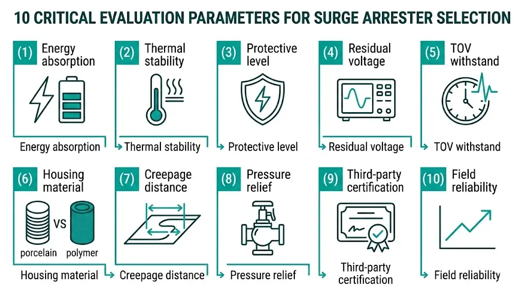
This guide provides the technical framework for evaluating surge arrester manufacturers based on parameters that actually predict field performance. Rather than ranking specific companies, we examine ten criteria that separate quality suppliers from those offering specification-sheet compliance with hidden compromises.
Rated voltage (Ur) defines the maximum continuous operating voltage an arrester can withstand indefinitely. Think of it as the arrester’s “system address”—it confirms compatibility with your network voltage, nothing more.
Two 36 kV arresters from different manufacturers can differ dramatically in:
These differences determine whether an arrester provides decade-long protection or becomes a recurring replacement expense.
Manufacturers optimizing for price minimize material in MOV (metal-oxide varistor) blocks, use thinner housings, and skip extended thermal testing. The arrester passes type tests but lacks margin for repeated real-world stress.
Quality manufacturers design for specific application profiles—distribution feeders, capacitor switching, cable protection, transformer terminals—each requiring different performance envelopes beyond identical kV ratings.
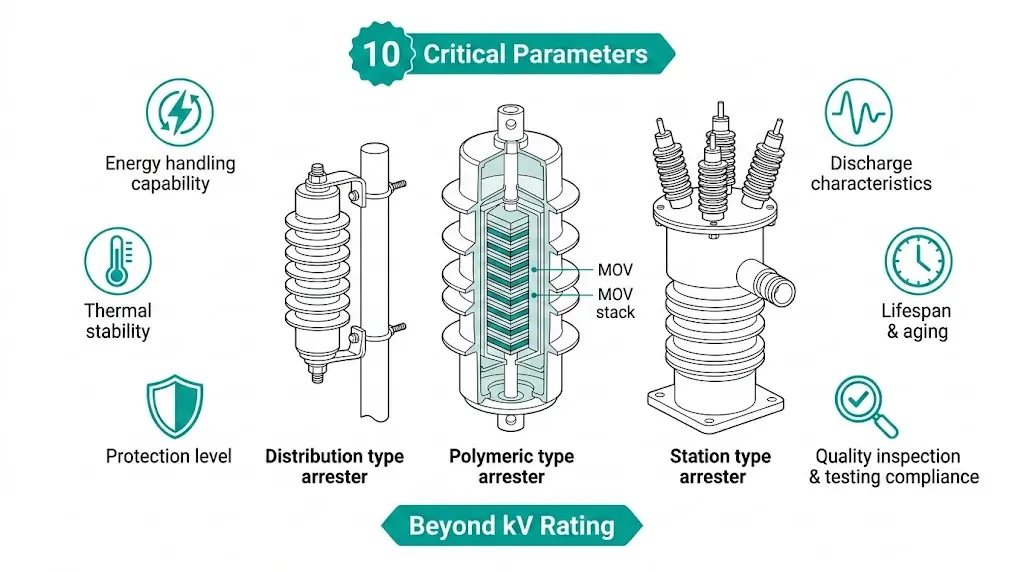
Energy absorption capacity determines how much transient energy the MOV blocks can dissipate without thermal runaway. Distribution-class arresters typically handle 2.5–4.5 kJ/kV, while station-class units provide 9–14 kJ/kV.
According to IEC 60099-4, arresters must survive multiple charge transfer events totaling 0.4–2.0 coulombs depending on line discharge class. Request operating duty test results—not catalog specifications—when evaluating manufacturers.
After absorbing surge energy, MOV blocks heat up. Quality arresters dissipate this heat before the next event. Poor thermal designs accumulate temperature until the zinc oxide material enters thermal runaway—a self-reinforcing heating cycle ending in failure.
In our field assessments across 80+ industrial substations, arresters with superior thermal designs maintained stable operation after 1,000+ surge impulses of 10 kA magnitude. Economy-grade materials exhibited measurable degradation after 200–400 impulses.
Protective level is the maximum voltage appearing across the arrester during discharge—the actual “clamping” voltage protecting downstream equipment. Two 36 kV arresters might specify:
That 14 kV difference directly affects insulation coordination margins. Lower protective levels allow either reduced BIL requirements for protected equipment or greater safety margins with existing insulation.
Residual voltage at various discharge currents (1 kA, 5 kA, 10 kA, 20 kA) reveals performance across the realistic range of surge magnitudes. Request complete residual voltage curves, not single-point specifications.
Premium zinc oxide varistors maintain flatter voltage-current characteristics, with residual voltage increase typically limited to 15–25% between 5 kA and 20 kA discharge currents.
TOV capability defines how long an arrester survives temporary system overvoltages during faults or load rejection events. Standard arresters withstand 1.4× rated voltage for 1 second. Enhanced designs handle 1.25× for 10 seconds or longer.
For systems with extended fault clearing times or weak grid connections, TOV withstand often determines arrester survival more than lightning performance.
Housing material affects thermal dissipation, contamination performance, and failure mode characteristics.
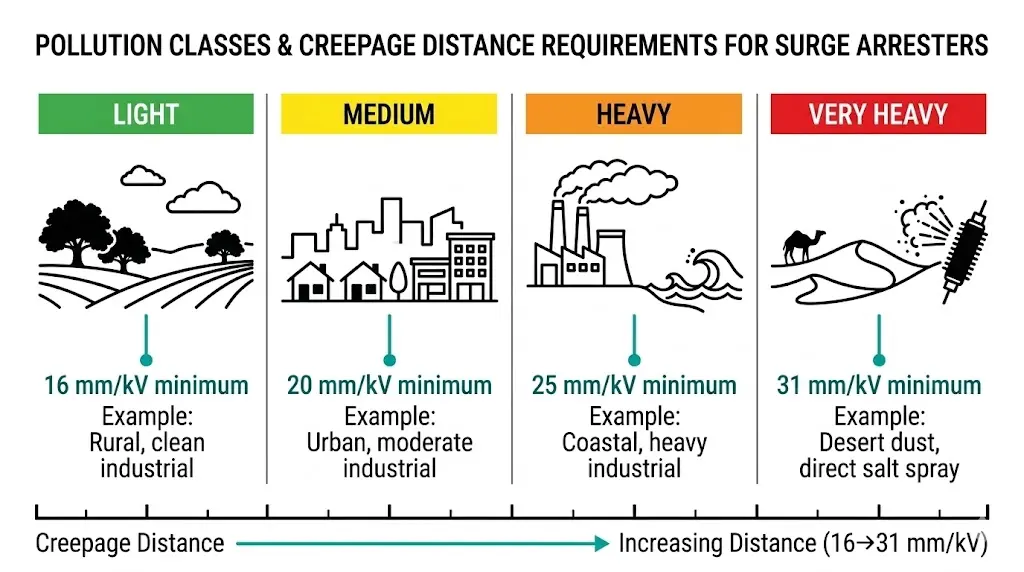
Creepage distance (mm/kV) determines pollution class suitability. Light pollution environments require 16 mm/kV minimum; heavy industrial or coastal installations need 25–31 mm/kV.
When arresters fail, pressure relief systems vent internal arc gases before housing rupture. Quality designs activate at pressures well below housing burst strength and direct venting away from personnel access areas.
Request IEC 60099-4 type test reports from accredited laboratories (KEMA, CESI, KERI, XIHARI). Manufacturers with genuine quality track records provide these without hesitation.
Ask for statistical reliability data from installed base. Quality manufacturers can provide failure rate data (failures per million arrester-years) from field populations. Warranty terms should align with stated service life claims.
[Expert Insight: MOV Quality Indicators]
- Nonlinearity coefficient (α) should range from 25–50 for quality ZnO formulations
- Residual voltage ratio (Ures/Ur) typically between 2.0–2.5 indicates proper design
- Power dissipation under continuous operating voltage should remain below 0.5 W/kVr
- Varistor switching voltage variation exceeding ±10% across production batches indicates quality control issues
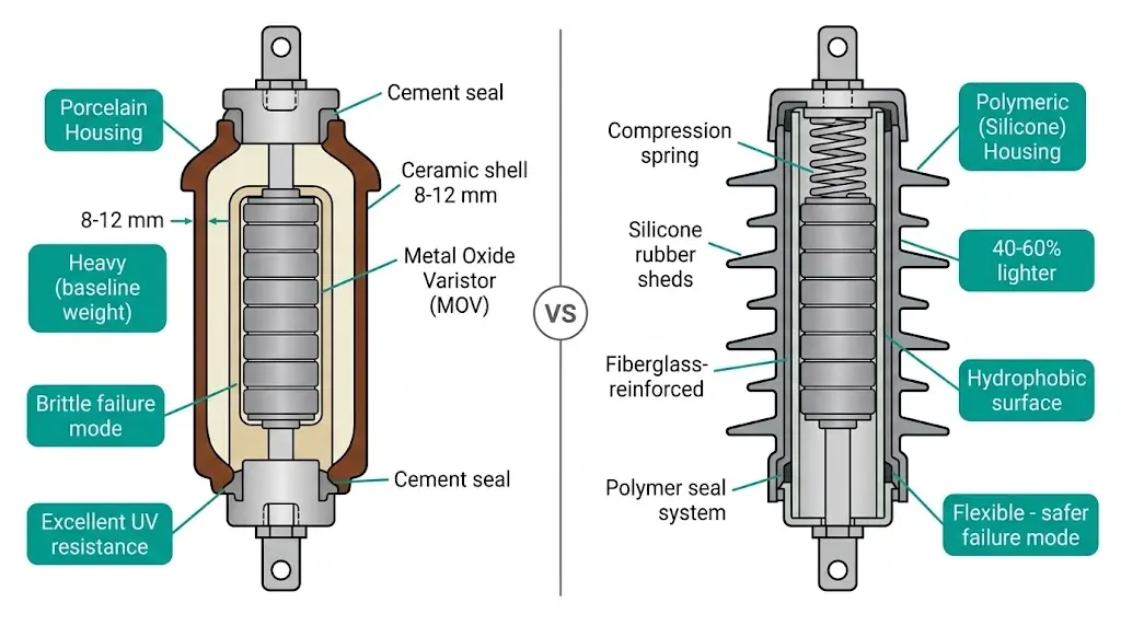
| Factor | Porcelain | Polymeric (Silicone) |
|---|---|---|
| Pollution performance | Requires periodic cleaning | Hydrophobic, self-cleaning |
| Weight | Heavy (baseline) | 40–60% lighter |
| Seismic withstand | Brittle failure mode | Flexible, superior performance |
| Failure mode | Shattering risk, shrapnel hazard | Splits, lower fragmentation |
| UV resistance | Excellent | Requires stabilized formulation |
| Tracking resistance | >4.5 kV per IEC 60587 | Class HC4 minimum for polluted sites |
| Initial cost | Lower | Higher |
| Lifecycle cost | Higher (maintenance) | Lower (reduced cleaning) |
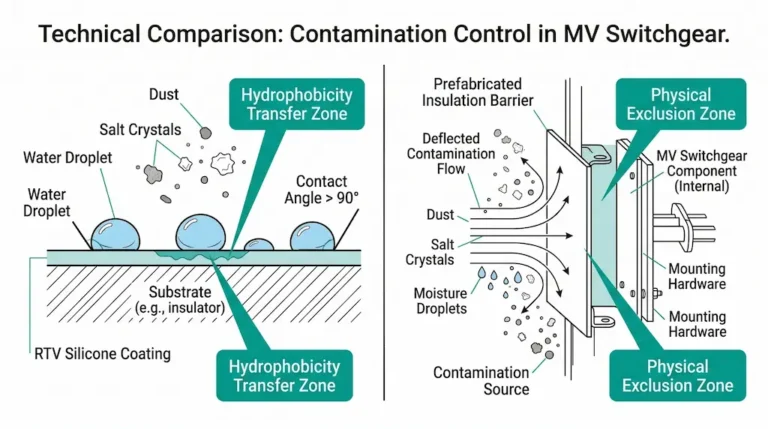
In coastal installations with high salt contamination, polymer silicone rubber housings show hydrophobicity recovery within 24–48 hours after pollution events. This self-cleaning property maintains creepage distance effectiveness without manual intervention.
For installations alongside switchgear parts and components in outdoor substations, polymeric housings dominate new installations due to superior pollution withstand and safer failure characteristics.
Above 1,000 m elevation, reduced air density decreases external flashover strength. Arresters require either increased creepage distance, voltage derating per manufacturer curves, or special high-altitude designs.
For outdoor pole-mounted VCB systems at high altitude, coordinating arrester ratings with circuit breaker insulation levels prevents protection gaps.
| Pollution Level | Minimum Creepage | Typical Environment |
|---|---|---|
| Light | 16 mm/kV | Rural, clean industrial |
| Medium | 20 mm/kV | Urban, moderate industrial |
| Heavy | 25 mm/kV | Coastal, heavy industrial |
| Very Heavy | 31 mm/kV | Desert dust, direct salt spray |
MOV characteristics shift with temperature. Verify minimum operating temperature (affects polymeric housing flexibility), maximum ambient temperature (affects thermal stability margins), and solar radiation allowance for exposed installations.
When selecting indoor vs outdoor circuit breaker configurations, arrester environmental ratings must match the switchgear installation class.
Polymeric arresters outperform porcelain in seismic applications. For high-seismic installations, verify dynamic withstand testing per IEEE 693 or equivalent regional standards.
[Expert Insight: Field Deployment Lessons]
- Arresters in areas exceeding 40 thunderstorm days annually show accelerated degradation within 5–8 years if energy ratings are inadequate
- Temperature differentials exceeding 15°C across individual varistor stacks indicate inconsistent current distribution—a red flag during acceptance testing
- Hydrophobicity recovery testing matters more than initial hydrophobicity measurements for long-term pollution performance
- Systems with >15% renewable penetration may experience 20–30% more switching surge events annually compared to conventional grids
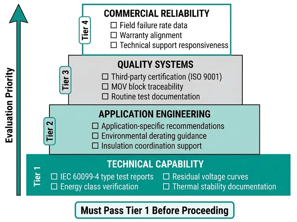
Tier 1 — Technical Capability (Must Pass)
Tier 2 — Application Engineering
Tier 3 — Quality Systems
Tier 4 — Commercial Reliability
Manufacturers strong across all four tiers justify price premiums. Those weak in Tier 1—regardless of pricing—present unacceptable risk to protected equipment worth 50–500× the arrester cost.
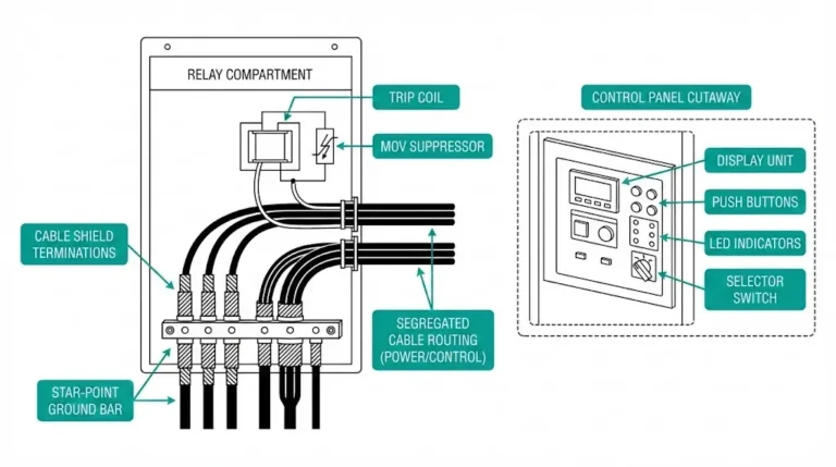
Surge arresters function as part of a coordinated insulation system. Their protective levels must remain below the BIL of protected equipment—transformers, cables, and vacuum circuit breaker protection systems—while staying above the maximum continuous operating voltage plus temporary overvoltage allowance.
Proper coordination requires:
According to IEC 60099-5 application guidelines, the protective margin for transformer protection should exceed 20% under lightning impulse conditions. For a 35 kV system with transformer BIL of 200 kV, the arrester residual voltage should remain ≤167 kV to achieve minimum margin requirements.
When specifying switchgear systems, arrester selection should occur during system design—not as an afterthought. Integrated suppliers ensure coordination between arresters, circuit breakers, and instrument transformers from the project’s outset.
Selecting surge arresters requires balancing technical requirements against verified manufacturer capability. The ten parameters outlined above separate quality manufacturers from those offering minimum-compliance products at attractive prices.
XBRELE provides surge arresters alongside complete medium-voltage switchgear systems—ensuring protection coordination across your installation. As an established switchgear component manufacturer, we supply type-tested equipment with full documentation and application engineering support.
Request a technical consultation to discuss arrester selection for your specific system voltage, environmental conditions, and protection coordination requirements.
Q: What causes most surge arrester failures in the field?
A: Cumulative thermal stress from repeated surge events—rather than single catastrophic strikes—accounts for the majority of arrester degradation, particularly when energy absorption capacity is marginal for the application’s surge duty profile.
Q: How do I verify a manufacturer’s energy absorption claims?
A: Request line discharge class test reports per IEC 60099-4 from accredited third-party laboratories; manufacturers unable to provide independent verification typically rely on internal testing that may not reflect production consistency.
Q: What protective margin should I maintain between arrester residual voltage and equipment BIL?
A: A minimum 15–20% margin between arrester residual voltage at nominal discharge current and protected equipment BIL provides adequate coordination; critical installations or those with long separation distances may require 25% or higher margins.
Q: When does polymeric housing outperform porcelain for surge arresters?
A: Polymeric silicone rubber housing provides superior performance in polluted environments (coastal, industrial, desert), seismic zones, and installations where failure mode safety is prioritized—though porcelain remains viable for clean indoor environments with minimal seismic risk.
Q: How often should surge arresters be replaced even without visible failure?
A: Most quality surge arresters are designed for 20–25 year service life under normal duty; however, arresters in high-lightning regions (>40 thunderstorm days annually) or those protecting critical equipment warrant leakage current monitoring after 10–15 years to detect gradual degradation before failure.
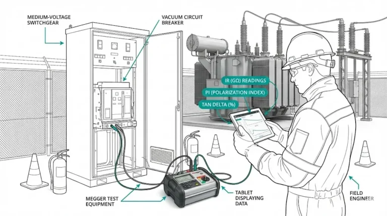
Q: Can surge arresters be tested in the field without removal?
A: Leakage current measurement under energized conditions provides the primary field diagnostic—resistive leakage current exceeding manufacturer thresholds (typically >100–200 μA total at continuous operating voltage) indicates MOV degradation requiring replacement evaluation.
Q: What documentation should I require before accepting surge arrester shipments?
A: Minimum documentation includes routine test certificates showing residual voltage measurements, reference voltage at 1 mA, and insulation resistance; for critical applications, request thermal imaging of varistor stacks during factory acceptance testing.