Need Full Specifications?
Download our 2025 Product Catalog for detailed drawings and technical parameters of all switchgear components.
Get CatalogDownload our 2025 Product Catalog for detailed drawings and technical parameters of all switchgear components.
Get CatalogDownload our 2025 Product Catalog for detailed drawings and technical parameters of all switchgear components.
Get Catalog
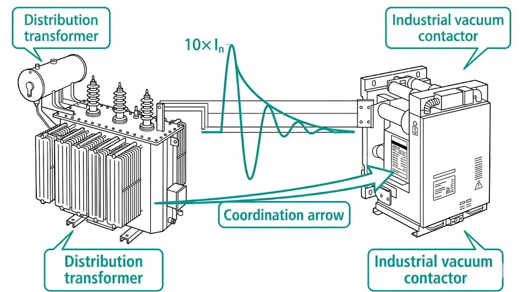
Energizing a transformer through a contactor is not a gentle event. The magnetic core demands instant flux establishment—and when closing occurs at an unfavorable voltage angle, core saturation drives magnetizing current to peaks of 8–12× rated value. Sometimes higher.
This inrush phenomenon has caused premature contact erosion, nuisance protection trips, and coordination failures across countless industrial installations. Standard motor-switching contactors simply weren’t designed for it.
This guide covers what engineers specifying vacuum contactors for transformer duty must understand: the physics driving inrush severity, coordination principles that prevent premature failure, and a complete specification checklist ready for your next RFQ.
Transformer inrush and motor starting current look similar on paper—both produce high multiples of rated current. The physics, however, diverge significantly.
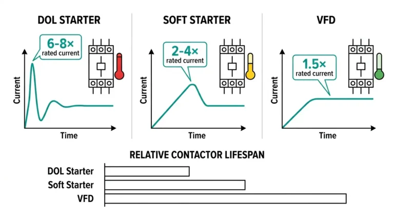
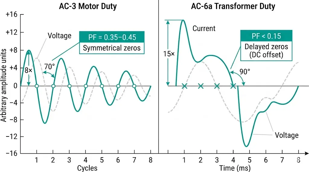
Motor starting current results from locked-rotor impedance. The waveform remains symmetrical, decays predictably as the rotor accelerates, and presents natural current zeros for arc extinction. Contactors rated AC-3 handle this reliably.
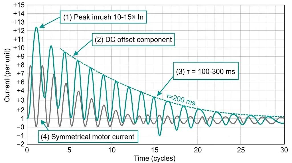
Transformer inrush originates from core saturation. When voltage applies at zero-crossing while residual flux remains in the core, the magnetic circuit attempts to establish flux exceeding twice normal peak value. The core saturates, permeability collapses, and magnetizing inductance drops by a factor of 100 or more.
The resulting current waveform contains substantial DC offset—sometimes 1.8× the AC peak component. This asymmetry delays natural current zeros, extending arc duration during contact separation. Field measurements across distribution networks show inrush peaks persisting 100–500 ms before decaying below twice rated current.
Peak inrush magnitude depends on three primary factors: (1) point-on-wave switching angle θ, where θ = 0° produces maximum inrush; (2) residual flux polarity and magnitude Br; and (3) core material saturation characteristics. Peak inrush current Ipeak typically reaches 8–15 × Irated for distribution transformers rated 50–2000 kVA.
Standard AC-3 contactors assume power factors of 0.35–0.45 with inrush durations under 10 cycles. Transformer magnetizing inrush presents power factors below 0.15 and durations of 5–25 cycles. The mismatch accelerates contact erosion dramatically—testing has revealed contact welding failures when AC-3 rated contactors attempt transformer switching beyond 50 duty cycles.
Not all transformers produce identical inrush. Core material, transformer rating, and residual flux conditions create significant variation that affects contactor selection.
Core Material Influence
Grain-oriented silicon steel—the dominant material in distribution transformers—saturates at approximately 1.9–2.0 Tesla. After de-energization, cores retain residual flux of 0.5–0.8 T. When re-energization polarity aligns with this residual flux, combined flux requirements push saturation deeper, amplifying inrush peaks.
Amorphous metal cores saturate at lower flux densities (1.5–1.6 T) but exhibit reduced residual flux retention. Transformers using amorphous cores typically produce inrush peaks 15–25% lower than equivalent silicon steel designs.
Transformer Rating Effects
Smaller transformers generate proportionally higher inrush multipliers. A 50 kVA dry-type unit may exhibit 15× inrush, while a 2,000 kVA oil-filled transformer typically stays below 10×. This inverse relationship stems from the higher per-unit magnetizing impedance in larger designs.
In field deployments across manufacturing facilities, we’ve documented that transformers below 100 kVA present the most challenging inrush conditions for contactor coordination—yet these applications often receive the least engineering attention.
Source Impedance Impact
Supply system impedance limits peak inrush magnitude. Installations fed from weak networks (impedance >4%) experience self-limiting inrush behavior. Strong supplies with impedance below 2% allow full theoretical inrush peaks to develop.
[Expert Insight: Field Observations on Inrush Variability]
- Cold energization after extended outages produces worst-case inrush; warm re-closure within 30 minutes reduces peaks by 20–35%
- Toroidal transformers can exceed 25× inrush due to efficient core geometry and high residual flux retention
- Three-phase transformers with delta windings exhibit lower inrush than equivalent wye configurations
- Point-on-wave controlled closing reduces inrush by 50–70% but adds $800–2,000 to contactor cost
IEC 60947-4-1 defines utilization categories that determine contactor suitability for specific load types. Misunderstanding these categories causes most transformer-contactor coordination failures.
AC-3 Category Limitations
AC-3 ratings apply to squirrel-cage motor starting and switching. The standard assumes:
These assumptions fail for transformer applications. The low power factor of magnetizing current (<0.15) means current and voltage remain nearly 90° out of phase. Arcs extinguish at current zero while substantial recovery voltage exists across contacts—promoting restrike and extended arcing.
AC-6a Category Requirements
The AC-6a utilization category specifically addresses transformer switching. Per IEC 60947-4-1, AC-6a contactors must:
For JCZ series vacuum contactors and similar medium-voltage devices, IEC 62271-106 provides equivalent guidance, specifying inrush withstand of 10× rated current with DC time constants up to 120 ms.
Comparison Table: Utilization Category Requirements
| Parameter | AC-3 (Motor) | AC-6a (Transformer) |
|---|---|---|
| Typical inrush multiple | 6–8× | 10–25× |
| Power factor during inrush | 0.35–0.45 | 0.10–0.20 |
| Inrush duration | <10 cycles | 5–25 cycles |
| DC offset component | Minimal | Significant |
| Making capacity requirement | 10× Ie | 25× Ie minimum |
Proper coordination requires matching contactor ratings to calculated inrush parameters—not simply selecting based on transformer nameplate current.
Step 1: Calculate Transformer Full-Load Current
For three-phase transformers:
Example: 500 kVA transformer at 6.6 kV
Step 2: Determine Expected Inrush Peak
Apply appropriate inrush multiplier based on transformer type:
For worst-case coordination, use the upper multiplier with 1.2× safety factor.
Example: 500 kVA dry-type transformer
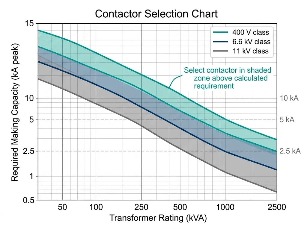
Step 3: Verify Contactor Making Capacity
The contactor’s making capacity (peak let-through current) must exceed calculated inrush. Making capacity appears on datasheets as peak kA or peak amperes—not RMS values.
Step 4: Confirm Thermal Withstand
Calculate inrush I²t energy and verify it falls below contactor thermal damage threshold:
Coordination Reference Table
| Transformer | Voltage | FLA | Inrush Peak (15×) | Min. Making Capacity |
|---|---|---|---|---|
| 100 kVA | 400 V | 144 A | 2,592 A | 3.5 kA |
| 250 kVA | 400 V | 361 A | 6,498 A | 8.0 kA |
| 500 kVA | 6.6 kV | 44 A | 786 A | 1.0 kA |
| 1,000 kVA | 11 kV | 52 A | 943 A | 1.2 kA |
Contact degradation in transformer switching applications follows different patterns than motor-control duty. Understanding these mechanisms enables realistic maintenance planning.
Erosion Rate Acceleration
Silver-tin oxide (AgSnO₂) contacts—standard in industrial contactors—erode at 0.1–0.3 mg per operation under transformer inrush conditions. Equivalent resistive load switching produces erosion below 0.02 mg per operation. This 5–15× acceleration directly impacts service life.
The erosion mechanism involves localized melting during contact bounce. When contacts close onto high inrush current, electromagnetic forces cause micro-separations that draw arcs. Each arc event removes contact material through vaporization and spatter.
Contact Welding Risks
Sustained inrush current during contact bounce can weld contacts together. Once welded, the contactor fails to open—creating a protection coordination hazard. We’ve documented welding failures within 6 months when facilities used AC-3 contactors for transformer switching exceeding 20 operations daily.
Practical Service Life Expectations
For properly rated AC-6a contactors in transformer duty:
For switchgear components including replacement contacts, specifying the correct material grade and erosion allowance ensures availability when maintenance intervals arrive.
[Expert Insight: Maintenance Observations from Industrial Installations]
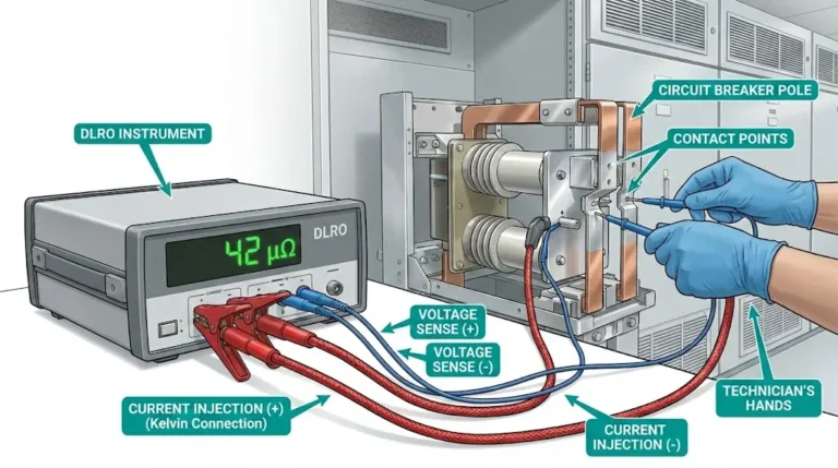
- Contact resistance measurements above 50 μΩ indicate significant erosion—schedule replacement
- Silver-cadmium oxide contacts (AgCdO) exhibit 25% better inrush performance but face environmental restrictions
- Vacuum contactors eliminate arc erosion concerns entirely for medium-voltage transformer switching
- Cumulative I²t tracking (where available) provides more accurate remaining life estimation than operation counters alone
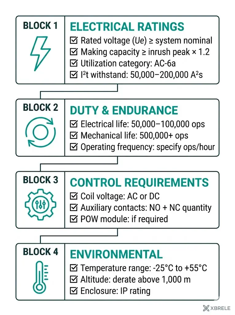
Engineers preparing RFQs for transformer switching applications should include these parameters to ensure proper coordination.
Electrical Ratings
| Parameter | Requirement | Notes |
|---|---|---|
| Rated operational voltage (Ue) | ≥ System nominal | 400 V, 6.6 kV, 11 kV typical |
| Rated operational current (Ie) | ≥ 1.25 × transformer FLA | Include margin for harmonics |
| Making capacity (peak) | ≥ Calculated inrush peak × 1.2 | Verify peak value, not RMS |
| Utilization category | AC-6a minimum | Per IEC 60947-4-1 |
| Power frequency withstand | Per system BIL | 2.5 kV for LV; 28–38 kV for MV |
Duty and Endurance
| Parameter | Typical Range | Your Requirement |
|---|---|---|
| Electrical endurance (AC-6a) | 50,000–100,000 ops | ___ operations |
| Mechanical endurance | 500,000–2,000,000 ops | ___ operations |
| Operating frequency | ≤ 60 operations/hour | ___ ops/hour |
| Thermal withstand (I²t) | 50,000–200,000 A²s | ___ A²s |
Control and Integration
Environmental Specifications
Documentation Requirements
Request certified test reports showing:
Selecting contactors for transformer duty requires precise coordination between inrush characteristics, switching frequency, and long-term reliability expectations. Generic AC-3 selections lead to premature failures; proper AC-6a coordination ensures decades of reliable service.
XBRELE engineers review your specific transformer ratings, inrush profiles, and operational cycles to recommend contactors that deliver verified performance. Our technical team provides:
Ready to specify your transformer switching solution?
Contact XBRELE’s vacuum contactor team for engineering consultation and technical datasheets tailored to your application requirements.
What inrush current should I expect when energizing a distribution transformer?
Distribution transformers typically produce inrush peaks of 8–12× rated full-load current for oil-filled designs and 10–15× for dry-type units. Actual magnitude depends on point-on-wave at closing, residual core flux, and source impedance—worst-case cold energization at voltage zero-crossing with aligned residual flux produces maximum values.
Can I use an AC-3 rated contactor for transformer switching?
AC-3 contactors may function initially but typically fail prematurely in transformer applications. The asymmetrical inrush waveform with DC offset exceeds AC-3 design assumptions, accelerating contact erosion by 5–15× compared to motor switching duty and causing potential welding failures within months at moderate switching frequencies.
How does point-on-wave controlled closing reduce transformer inrush?
Controlled closing synchronizes contact engagement with optimal voltage phase angle (near peak voltage rather than zero-crossing), reducing inrush by 50–70%. This approach requires electronic controllers with closing accuracy of ±1–2 ms and adds cost, but significantly extends contact life in high-cycle applications.
What altitude derating applies to transformer switching contactors?
Above 1,000 m elevation, reduced air density diminishes dielectric strength and heat dissipation capability. Per IEC 62271-1, apply voltage derating of approximately 1% per 100 m above 1,000 m. Current ratings may also require 2–3% derating per 500 m for thermal reasons—always specify actual installation altitude in procurement documents.
How often should contactors be maintained in transformer switching service?
Annual inspection is recommended for transformer switching duty with moderate frequency (10–30 operations daily). Check contact resistance (replace above 50 μΩ), verify operation counter readings against expected life, inspect arc chute condition, and test auxiliary contact function. High-frequency applications (>50 operations daily) may require semi-annual inspection.
Why is making capacity more critical than breaking capacity for transformer applications?
Transformer energization subjects contactors to extreme current during contact closure (making), while breaking current equals only the small magnetizing current (typically 1–3% of rated). Making capacity determines whether contacts survive repetitive inrush events without welding—breaking capacity matters primarily for fault conditions handled by upstream protection.
What contact material performs best for transformer inrush duty?
Silver-tin oxide (AgSnO₂) provides good performance with environmental compliance. Silver-cadmium oxide (AgCdO) offers approximately 25% better inrush resistance but faces regulatory restrictions. For medium-voltage applications, vacuum interrupters with copper-chromium contacts eliminate atmospheric arc erosion entirely, offering superior service life in demanding transformer switching applications.