Need Full Specifications?
Download our 2025 Product Catalog for detailed drawings and technical parameters of all switchgear components.
Get CatalogDownload our 2025 Product Catalog for detailed drawings and technical parameters of all switchgear components.
Get CatalogDownload our 2025 Product Catalog for detailed drawings and technical parameters of all switchgear components.
Get Catalog
Vacuum circuit breakers fail in predictable ways. Contact erosion from arc energy, timing drift from mechanism wear, insulation degradation from moisture—these deterioration modes announce themselves through measurable indicators months before catastrophic failure.
Unlike contactors that switch loads thousands of times annually, VCBs interrupt faults occasionally but must perform flawlessly when called. A single failure to clear a short circuit cascades: equipment damage, extended downtime, safety incidents. The difference between a VCB that clears a 25 kA fault in 50 ms and one that fails to interrupt costs tens or hundreds of thousands of dollars.
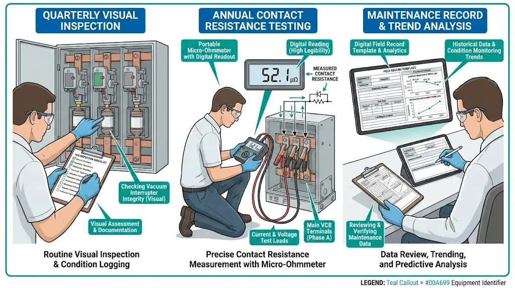
Maintenance catches deterioration early. A quarterly visual inspection identifies loose connections before they cause arcing damage. An annual timing test reveals 15% slower opening speed—not yet a failure, but trending toward the replacement threshold. Structured maintenance transforms random failures into planned replacements during scheduled outages.
This checklist provides the specific quarterly and annual maintenance tasks, acceptance criteria, and field record templates engineers need to maintain vacuum circuit breaker reliability across utility, industrial, and commercial installations rated 12–40.5 kV.
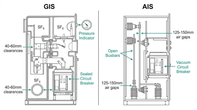
Circuit breakers and contactors both use vacuum interrupters, but their maintenance requirements differ significantly.
Duty cycle comparison:
| Parameter | Vacuum Circuit Breaker | Vacuum Contactor |
|---|---|---|
| Primary function | Fault interruption | Load switching |
| Operations/year | 5–20 (rare fault clearing) | 5,000–50,000 (frequent load switching) |
| Current interrupted | 10–40× rated (short circuit) | 1–8× rated (inrush/normal) |
| Arc energy per operation | Very high (kA-level faults) | Moderate (load-level currents) |
| Cumulative arc energy | Moderate (few operations × high energy) | High (many operations × moderate energy) |
| Failure consequence | Catastrophic (equipment destruction, safety) | Moderate (process interruption) |
| Maintenance priority | Protection integrity | Operational reliability |
VCB maintenance emphasizes readiness—ensuring the breaker will operate correctly during the rare fault event. Contactor maintenance emphasizes endurance—tracking cumulative wear from frequent switching.
Maintenance requirements also vary by VCB lubrication and overhaul strategy as well as design, voltage class, and application environment. Indoor switchgear may require more frequent cleaning in dusty environments, while outdoor installations face weathering and temperature cycling challenges.
Both require contact resistance measurement and vacuum integrity checks, but VCBs add critical focus on timing/travel (interrupting capability depends on opening speed) and protection coordination (relay settings must match actual breaker performance).
Combine time-based, operation-based, and condition-based triggers for comprehensive coverage.
Scope: Visual inspection, basic functional checks
Duration: 30–60 minutes per breaker
Can be performed: During facility rounds, minimal production impact
Tasks:
Scope: Detailed electrical and mechanical testing
Duration: 2–4 hours per breaker
Requires: Breaker isolation, specialized test equipment, trained personnel
Tasks:
Scope: Comprehensive assessment, often coincides with major outages
Duration: Full day per breaker (with panel access)
Tasks:
Independent of time, perform full inspection after:
Track operations via:
Perform immediate unscheduled inspection when:
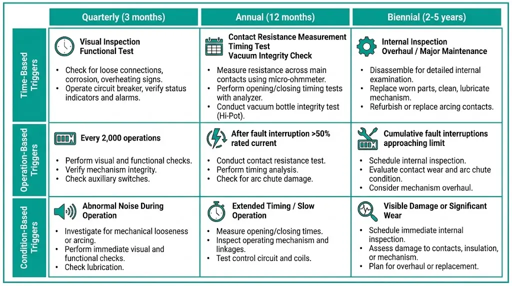
Quarterly checks catch developing problems before they require emergency repairs.
Check for:
Acceptance criteria:
Corrective actions:
Procedure:
Acceptance:
Issues indicating detailed inspection needed:
Voltage measurement:
Measure DC control voltage at:
Acceptance: 85–110% of rated voltage (e.g., 110–138 V for 125 VDC system)
Low voltage (<85%): Indicates wiring voltage drop, weak battery, charger failure
High voltage (>110%): Indicates charger malfunction, potential coil damage
Auxiliary contact check:
Critical connections (check annually, spot-check quarterly):
Use calibrated torque wrench per manufacturer specifications (typically):
Signs of loose connections:
Record for trending:
High temperature (>40°C sustained) or high humidity (>85% RH) accelerates insulation degradation—may require derating or environmental control improvements.
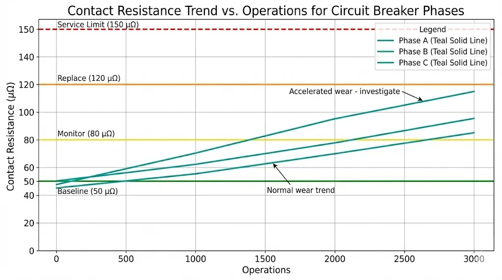
Annual tests verify electrical and mechanical integrity through measurable parameters.
Purpose: Detect contact erosion, contamination, misalignment before resistance causes overheating or interrupting capability loss. For field setup details, use this micro-ohm contact resistance testing procedure.
Equipment:
Procedure:
Typical values for 12–36 kV VCBs:
Evaluation:
| Resistance | Trend | Action |
|---|---|---|
| <80 μΩ | Stable | Acceptable, continue monitoring |
| 80–120 μΩ | Increasing gradually | Monitor at next interval, plan replacement |
| >120 μΩ | Approaching limit | Replace contacts at next outage |
| >150 μΩ | Exceeded service limit | Immediate replacement required |
| Sudden jump (>50% increase) | Abnormal | Retest to confirm; if confirmed, investigate misalignment or contamination |
Pole-to-pole variation:
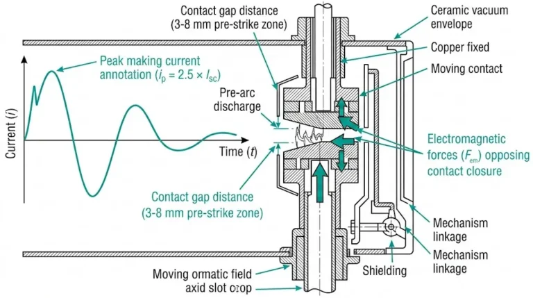
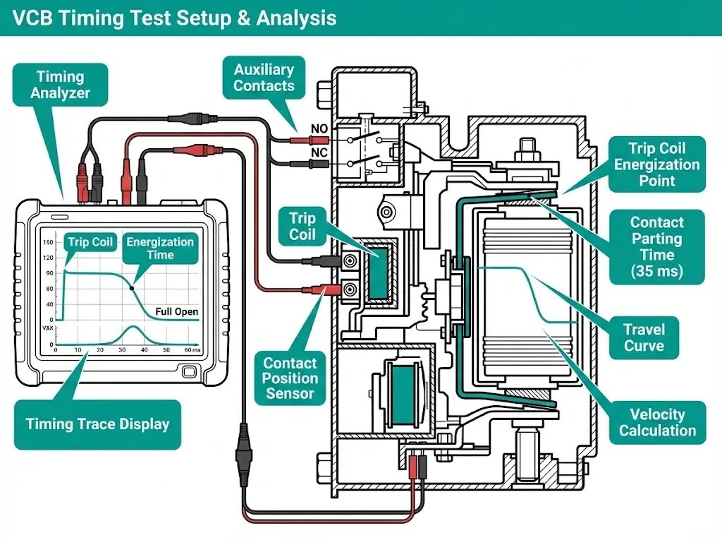
VCB interrupting capability depends on opening speed. Timing tests verify mechanism performance against manufacturer specifications and should be reviewed with contact-gap and alignment limits before mechanical adjustment.
Equipment needed:
Measurements:
Opening time: Time from trip coil energization to contact separation
Closing time: Time from close coil energization to contact touch
Contact travel: Total distance contacts move from fully open to fully closed
Velocity: Average contact separation speed during opening
Procedure:
Acceptance criteria:
Out-of-spec conditions:
| Symptom | Likely Cause | Remedy |
|---|---|---|
| Opening time slow (>10% over spec) | Dried lubricant, spring fatigue, friction | Lubricate, adjust, replace springs |
| Opening time fast (>10% under spec) | Over-tensioned springs, reduced damping | Adjust spring tension, check damper |
| Inconsistent timing (varies >15% between operations) | Binding, mechanical play, latch wear | Inspect mechanism, replace worn parts |
| Low travel (<90%) | Mechanism wear, vacuum interrupter swelling (vacuum loss) | Adjust mechanism; if vacuum lost, replace VI |
| Excessive travel (>110%) | Stop adjustment lost, over-travel damage risk | Adjust mechanical stops |
Verifies insulation integrity between live parts and ground, preventing leakage currents and flashovers.
Equipment: Insulation resistance tester (Megger), 2.5 kV or 5 kV test voltage
Test points:
Low insulation resistance (<100 MΩ on main circuit):
Trending: Track insulation resistance over time. Gradual decrease indicates developing problem even if still above minimum.
Vacuum interrupter dielectric strength depends on maintaining high vacuum (<10⁻⁴ Pa). Loss of vacuum may not prevent load switching but catastrophically fails during fault interruption.
Method 1: High-Voltage Withstand Test (most definitive)
Equipment: AC high-voltage test set, 10–50 kV adjustable
Procedure:
Acceptance:
Method 2: Insulation Resistance at Reduced Voltage (field-expedient)
Procedure:
Less definitive than high-voltage test but adequate for routine screening.
Method 3: Shield Current Measurement (advanced, requires specialized equipment)
Some manufacturers provide shield current measurement ports for non-invasive vacuum assessment.
Lubrication check:
Action:
Wear inspection:
Alignment check:
Auxiliary relays:
Protection relay settings:
Annunciation:
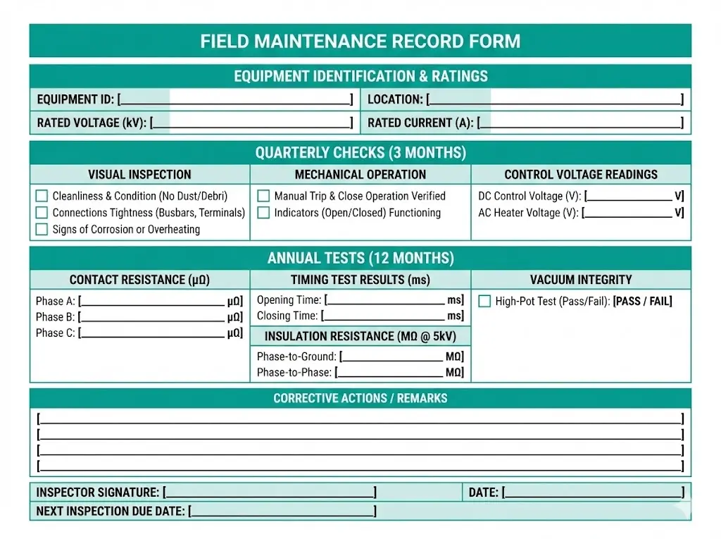
Consistent documentation enables trending analysis. Use this template or adapt to your CMMS system.
VACUUM CIRCUIT BREAKER MAINTENANCE RECORD

Equipment ID: ________________  Location: ________________
Manufacturer: ________________  Serial No: ________________
Rated Voltage: _______ kV      Rated Current: _______ A
Rated Short-Circuit: _______ kA   Year Installed: _______

MAINTENANCE TYPE: [ ] Quarterly  [ ] Annual  [ ] Post-Fault
Date: _______________  Operations Since Last Inspection: _______
Ambient Temp: _____ °C   Humidity: _____ %

═══════════════════════════════════════════════════════════

QUARTERLY CHECKS (if applicable):

Visual Inspection:
[ ] External clean, no tracking
[ ] No physical damage or cracks
[ ] No moisture/corrosion
[ ] Ventilation adequate

Mechanical Operation:
[ ] Closes smoothly
[ ] Trips promptly
[ ] Latches positively
[ ] Charging motor stops correctly

Control Voltage (measured):
Trip coil: _______ V (Spec: 85-110% of _____ V)
Close coil: _______ V
Auxiliary: _______ V

Connection Check:
[ ] No loose connections observed
[ ] No discoloration around terminals

═══════════════════════════════════════════════════════════

ANNUAL TESTS (if applicable):

CONTACT RESISTANCE (μΩ):
Phase A: _______ (Baseline: _____)  Status: [ ] OK  [ ] Monitor  [ ] Replace
Phase B: _______ (Baseline: _____)  Status: [ ] OK  [ ] Monitor  [ ] Replace
Phase C: _______ (Baseline: _____)  Status: [ ] OK  [ ] Monitor  [ ] Replace

TIMING TEST:
Opening time: _______ ms  (Spec: _____ ± _____ ms)  [ ] Pass  [ ] Fail
Closing time: _______ ms  (Spec: _____ ± _____ ms)  [ ] Pass  [ ] Fail
Contact travel: _______ mm  (Spec: _____ ± _____ mm)  [ ] Pass  [ ] Fail
Average velocity: _______ m/s  (Min spec: _____ m/s)  [ ] Pass  [ ] Fail

INSULATION RESISTANCE (MΩ):
Phase A to ground: _______  (Min: 1000 MΩ)  [ ] Pass  [ ] Fail
Phase B to ground: _______  (Min: 1000 MΩ)  [ ] Pass  [ ] Fail
Phase C to ground: _______  (Min: 1000 MΩ)  [ ] Pass  [ ] Fail
Control circuit: _______  (Min: 10 MΩ)  [ ] Pass  [ ] Fail

VACUUM INTEGRITY:
Test method used: [ ] HV withstand  [ ] Megger test  [ ] Shield current
Result: [ ] Pass (vacuum intact)  [ ] Fail (vacuum lost)
If failed: Interrupter replacement required: [ ] Yes

MECHANISM INSPECTION:
[ ] Lubrication condition acceptable
[ ] No excessive wear observed
[ ] Alignment within tolerance
[ ] Springs in good condition

═══════════════════════════════════════════════════════════

CORRECTIVE ACTIONS TAKEN:
____________________________________________________________
____________________________________________________________

PARTS REPLACED:
____________________________________________________________

NEXT INSPECTION DUE:
Date: _______________  OR  Operations: _______

BREAKER STATUS:
[ ] Returned to service (all tests passed)
[ ] Out of service (repairs required)
[ ] Contact replacement scheduled for: _______________

Inspector: _____________________  Signature: __________
Reviewed by: ___________________  Date: ____________
Individual measurements are snapshots. Trends reveal deterioration patterns.
Key parameters to trend:
Predictive maintenance actions:
Fleet trending:
If you maintain multiple identical VCBs, compare:
| Symptom | Diagnostic Test | Likely Cause | Remedy |
|---|---|---|---|
| Won’t trip | Check trip coil voltage | Under-voltage, open circuit | Correct voltage supply, repair wiring |
| Check mechanical linkage | Binding, mechanical jam | Free mechanism, lubricate | |
| Test anti-pumping circuit | False lockout | Reset relay, verify circuit | |
| Won’t close | Check close coil voltage | Under-voltage, coil failure | Correct supply, replace coil |
| Check mechanism charge | Spring discharged, hydraulic pressure low | Charge mechanism | |
| Verify interlocks | Interlock preventing close | Check interlock status, clear fault | |
| Slow opening time | Timing test | Lubrication dried, spring fatigue | Re-lubricate, replace springs |
| Measure spring force | Weak spring | Replace spring assembly | |
| Contact bounce | Timing trace analysis | Closing speed excessive, damping lost | Adjust closing speed, replace damper |
| High contact resistance | Resistance trending | Contact erosion, misalignment | Clean contacts (if accessible), replace if >limit |
| Low insulation resistance | Measure under controlled humidity | Moisture | Dry out panel, improve sealing |
| Visual inspection | Contamination, tracking | Clean insulators, replace if tracked | |
| Failed vacuum test | Vacuum integrity test | Vacuum interrupter degradation | Replace vacuum interrupter |
VCB maintenance involves stored energy, high voltage, and mechanical hazards.
Before starting work:
During testing:
After maintenance:
For detailed procedures on specific VCB types, consult manufacturer maintenance guides and this drawout VCB racking and alignment checklist.
External Reference: IEC 62271-106 — IEC 62271-106 standard for AC contactors
Q1: How often should I perform contact resistance testing on a VCB?
A: Annually for standard distribution VCBs, semi-annually for generator breakers or transfer schemes with frequent operations (>500 ops/year). Always test after any fault interruption >50% rated short-circuit current, as fault arc energy accelerates contact erosion.
Q2: What’s the difference between VCB maintenance and contactor maintenance?
A: VCBs emphasize protection readiness (timing accuracy, interrupting capability) while contactors emphasize operational endurance (cumulative wear tracking). VCBs require more detailed timing/travel analysis because fault interruption depends on precise contact separation speed; contactors focus more on contact resistance trending due to frequent arcing exposure.
Q3: Can I perform vacuum integrity testing without high-voltage equipment?
A: Yes—use 1,000–2,500 V Megger across open contacts as field-expedient screening test. Good vacuum shows >100 MΩ resistance. This method is less definitive than high-voltage withstand testing but adequate for routine annual checks. Perform high-voltage test every 3–5 years or if Megger results are marginal.
Q4: What causes timing to drift out of specification over time?
A: Primary causes: (1) lubrication aging—grease dries or liquifies, increasing friction; (2) spring fatigue—springs lose tension over thousands of operations; (3) mechanical wear—pivot holes elongate, linkage pins wear down, creating slack; (4) latch wear—reduces engagement time. Gradual drift is normal; sudden changes indicate specific component failure.
Q5: How do I know when to replace contacts vs. entire vacuum interrupter?
A: If contact resistance exceeds service limit (typically 150 μΩ) OR vacuum integrity fails, entire vacuum interrupter must be replaced—contacts and vacuum envelope are sealed unit that cannot be field-repaired. Cost: $300–$1,500 per interrupter depending on voltage/current rating. Replacement time: 2–6 hours per VCB.
Q6: Should quarterly and annual maintenance be performed by the same personnel?
A: Quarterly checks can be performed by facility electricians familiar with the equipment. Annual testing requires specialized test equipment (micro-ohmmeter, timing analyzer, HV test set) and training in interpretation of results—typically performed by dedicated maintenance technicians or contracted specialists.
Q7: How do fault interruptions affect maintenance intervals?
A: Each fault interruption causes significant contact erosion and mechanical stress. Perform contact resistance and timing tests after ANY fault interruption >50% of rated short-circuit current. Multiple fault operations may consume years of normal operational life in seconds—adjust replacement planning accordingly based on fault history, not just operation count.