Need Full Specifications?
Download our 2025 Product Catalog for detailed drawings and technical parameters of all switchgear components.
Get Catalog
Download our 2025 Product Catalog for detailed drawings and technical parameters of all switchgear components.
Get Catalog Download our 2025 Product Catalog for detailed drawings and technical parameters of all switchgear components.
Get Catalog
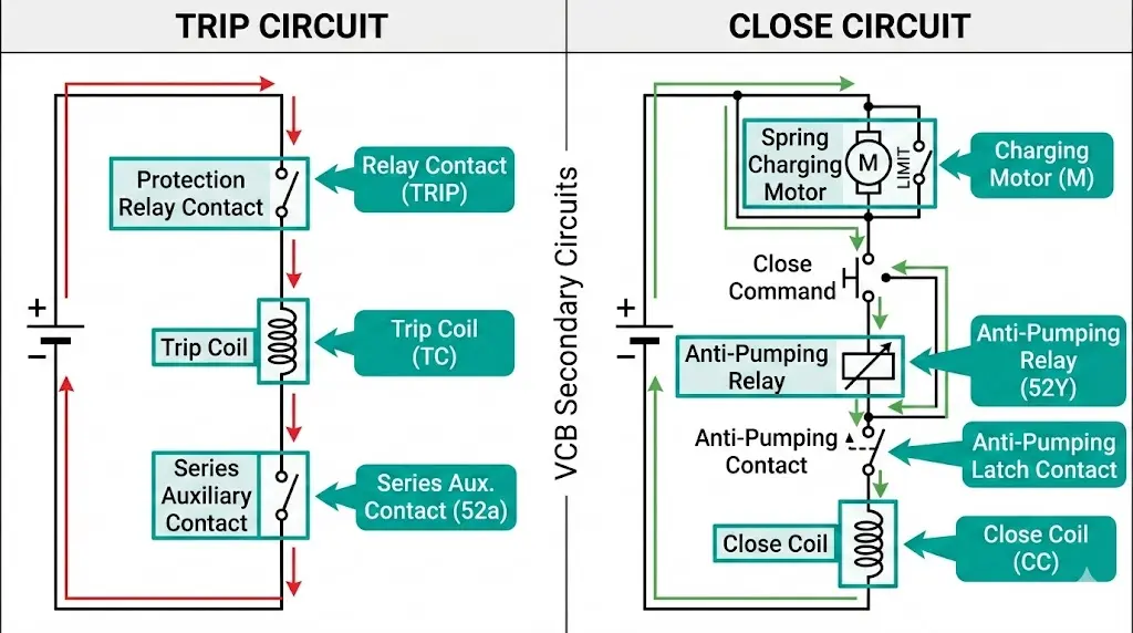
Circuit breaker primary circuits carry load and fault currents. Secondary circuits control when those operations happen. A vacuum circuit breaker’s main contacts might withstand 25 kA short-circuit current perfectly—yet the installation fails commissioning because the control wiring introduces nuisance trips, allows dangerous simultaneous closures, or permits motor pumping that destroys the mechanism.
Secondary circuit design separates properly engineered switchgear from field failures waiting to happen. The difference shows up in control logic details: trip coil supervision, anti-pumping relay placement, mechanical interlock verification, and auxiliary contact sequencing.
This guide breaks down VCB secondary circuits from the manufacturer’s engineering perspective. You’ll understand why certain circuit elements exist, how they prevent common failure modes, and what to verify during factory acceptance tests and site commissioning.
Primary circuits in a VCB conduct current from line side to load side through the vacuum interrupter contacts. Secondary circuits command those contacts to open or close, prevent improper operations, and report breaker status back to protection relays or SCADA systems.
Secondary circuits encompass:
Control circuits — Trip coil, close coil, spring charging motor circuits that directly actuate the mechanism
Auxiliary circuits — Status indication contacts, position signaling to interlocks and protection devices
Protection circuits — Anti-pumping logic, coil supervision, electrical/mechanical interlock circuits
Annunciation circuits — Alarms for motor failure, spring not charged, mechanism malfunction
Voltage levels vary by application. Most medium-voltage VCBs use 110 VDC or 220 VDC control power from station batteries. Some industrial installations specify 110 VAC or 220 VAC control. The circuit topology stays conceptually similar, though AC control introduces timing considerations around zero-crossing and requires different anti-pumping approaches.
[DESIGN NOTE: DC control allows operation during grid blackouts when station batteries provide backup power—critical for utility breakers protecting generators and transformers]
Understanding secondary circuits starts with the operating sequence. The vacuum circuit breaker working principle explained in this VCB operating principle guide shows how vacuum arc extinction requires precise contact motion—secondary circuits time and coordinate that motion across all operating conditions.
Trip and close circuits directly energize the solenoid coils or motors that actuate the VCB mechanism. Design priorities differ: trip circuits must be fail-safe and ultra-reliable, while close circuits must prevent dangerous simultaneous operations.
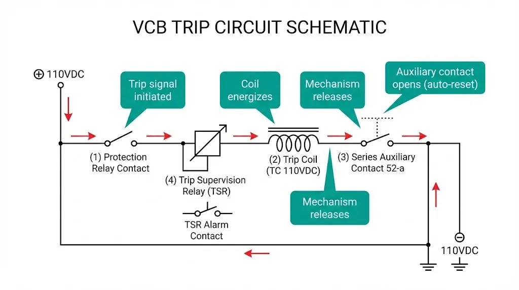
A typical trip circuit follows this signal path:
| Trip Circuit Element | Function | Typical Rating |
|---|---|---|
| Trip coil | Electromagnetic actuator releasing trip latch | 110/220 VDC, 5–10 A inrush |
| Series auxiliary contact | Auto-resets trip circuit once breaker opens | “a” contact, rated for coil current |
| Shunt trip release | Mechanical coupling between coil and latch mechanism | Force rated for mechanism spring |
| Trip supervision relay | Monitors coil circuit continuity | Alarm contact on open circuit |
The series auxiliary contact prevents trip coil burnout. Without it, the coil remains energized after the breaker trips, overheating and failing within minutes. Proper designs place an “a” (normally open, closed when breaker closed) auxiliary contact in series with the trip coil—when the mechanism trips, this contact opens automatically.
[OEM Design Insight: Trip Circuit Reliability]
- Redundant trip coils (Trip Coil 1 + Trip Coil 2) double reliability for critical applications
- Gold-plated trip coil terminals reduce contact resistance and corrosion failures
- Trip coil continuity supervision alarms alert operators before the breaker can’t trip when needed
- Fast-acting fuses protect trip circuits from short circuits without delaying protection operation
Close circuits charge stored energy (compressed spring or magnetic actuator) then release it to drive contacts closed. Because closing onto a fault creates extreme mechanical stress, close circuits include anti-pumping and interlock protection.
A spring-charged mechanism close sequence:
| Close Circuit Element | Function | Typical Rating |
|---|---|---|
| Close coil | Releases stored energy latch | 110/220 VDC, 3–8 A |
| Spring charging motor | Compresses closing spring | 110/220 VDC, 2–5 A continuous |
| Spring charged switch | Signals readiness for close operation | Mechanical limit switch |
| Anti-pumping relay | Prevents repeated close attempts on persistent faults | Auxiliary relay with seal-in circuit |
| Close interlock contacts | Prevents closing when unsafe (e.g., earthing switch closed) | Hard-wired “b” contacts |
The spring charging motor runs automatically after each close operation or can be manually initiated. A limit switch stops the motor when spring compression reaches the required force. If the motor fails or the spring mechanism jams, the “spring not charged” alarm activates.
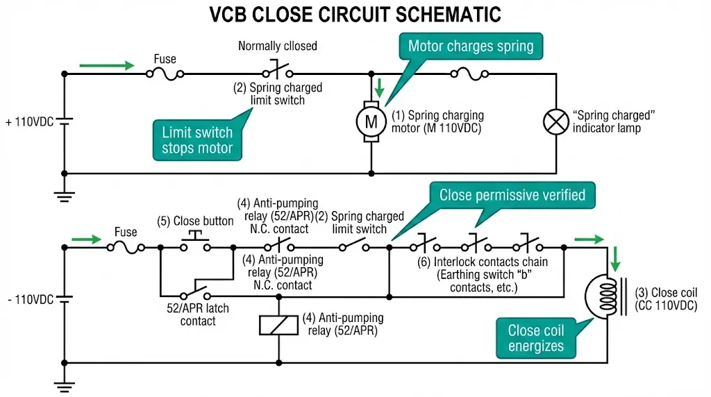
Anti-pumping protection prevents the VCB from repeatedly attempting to close onto a fault. Without it, the breaker cycles open-close-open-close rapidly, destroying the mechanism and potentially causing contact welding.
Consider this scenario without anti-pumping:
This “pumping” action subjects the mechanism to extreme mechanical shock at fault-current making capacity—far exceeding normal duty cycle ratings.
A properly designed anti-pumping circuit requires the close command to be reset (de-energized and re-energized) before allowing another close operation:
Control relay method:
Auxiliary contact method (simpler but less flexible):
| Anti-Pumping Method | Advantages | Limitations |
|---|---|---|
| Auxiliary relay with seal-in | Prevents pumping regardless of close signal duration; works with automatic reclosing | Adds relay cost and complexity |
| Breaker auxiliary contact only | Simple, no additional components | May not block all pumping scenarios in auto-reclose schemes |
| Programmable logic controller | Fully configurable, integrates with SCADA | Requires backup hardwired protection for safety-critical applications |

[Field Failure Case: Anti-Pumping Circuit Bypass]
A mining operation modified their switchgear to allow “forced closure” during emergencies by bypassing anti-pumping protection. During a cable fault, the operator held the close button attempting to restore power. The VCB pumped six times in 15 seconds before the mechanism shattered the spring guide. Replacement cost exceeded $45,000 plus two weeks downtime.
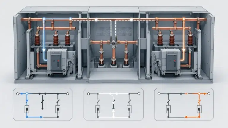
Interlocks prevent unsafe operating sequences: closing with the earthing switch engaged, operating two incomers simultaneously, or racking the breaker while energized. Implementation uses both hard-wired contacts (electrical interlocks) and physical blocking (mechanical interlocks).
Earthing switch interlock:
Busbar transfer interlock:
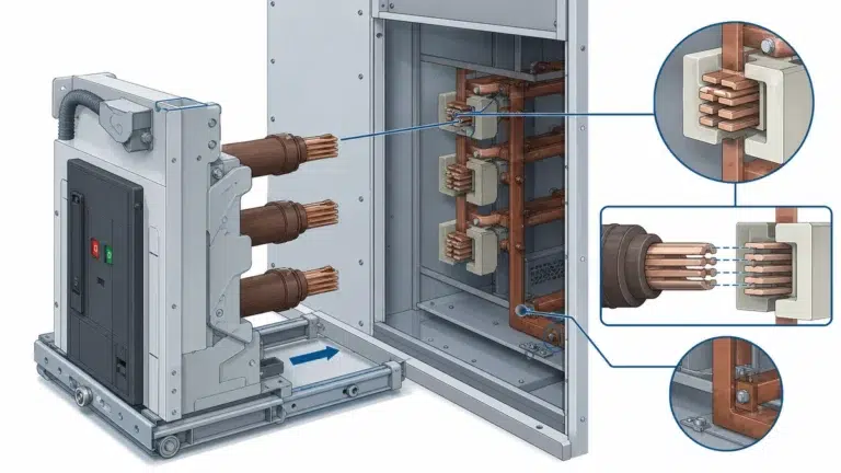
Withdrawable breaker interlock:
Key interlock systems:
Padlock provisions:
Racking interlock:
| Interlock Type | Primary Function | Redundancy Level |
|---|---|---|
| Electrical (hard-wired) | Prevents energization of control circuits | First-line defense |
| Mechanical (physical blocking) | Physically prevents mechanism motion or breaker positioning | Backup if electrical interlock fails or bypassed |
| Administrative (key/lock) | Enforces procedural compliance | Human factors layer |
OEM best practice combines all three layers for critical interlocks. For example, earthing switch safety typically requires electrical interlock (auxiliary contacts), mechanical blocking (latch), AND key interlock (sequence enforcement).
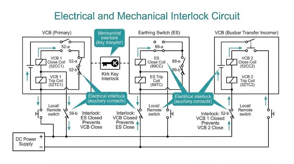
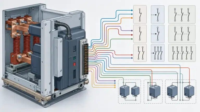
Auxiliary contacts report breaker position to protection relays, SCADA systems, alarms, and interlock circuits. Contact sequencing—the precise order contacts make and break during opening and closing—determines whether external circuits operate correctly.
“a” contacts (Normally Open):
“b” contacts (Normally Closed):
Most VCBs provide 6–12 auxiliary contacts as standard, expandable to 20+ with auxiliary contact blocks. Contacts rated 5–10 A at control voltage handle signaling and relay coil loads but cannot directly switch motors or heaters.
During closing operation:
During opening operation:
This sequencing ensures external circuits see the status change only after the VCB reaches a stable mechanical position. Early “breaker closed” signaling before contacts fully engage can cause protection miscoordination. Late “breaker open” signaling can delay earthing switch permissives, violating safety procedures.
| Sequence Requirement | Why It Matters |
|---|---|
| “a” closes after main contacts touch | Prevents false “closed” signal during bounce or incomplete closing |
| “b” opens after “a” closes | Avoids dead zone where both contacts open simultaneously (no status indication) |
| “b” closes before main contacts open | Provides “breaker opening” signal to relays before arc interruption |
| “a” opens before main contacts separate | De-energizes trip coil circuit before auxiliary contact arcing begins |
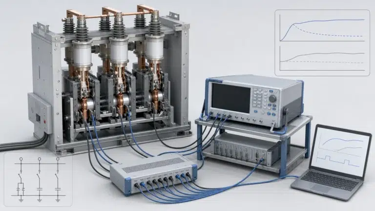
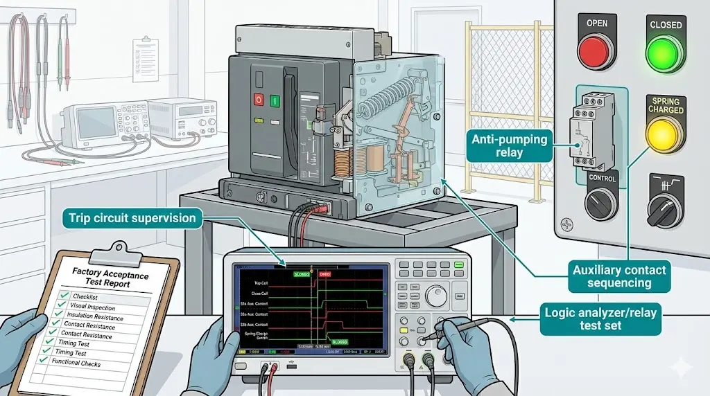
Auxiliary contact timing is verified during VCB type testing. Commissioning checks use simultaneous recording of main contact position and auxiliary contact transitions to confirm proper sequencing.
Control circuits fail when station batteries discharge, AC control transformers lose supply, or wiring develops high-resistance faults. Secondary circuit design must detect these failures and prevent unsafe conditions.
Continuous trip circuit monitoring ensures the breaker can trip when protection operates:
Supervision relay method:
Microprocessor-based monitoring:
VCBs with spring-operated mechanisms require stored energy to close. If spring motor fails or limit switch malfunctions, the breaker cannot close:
Low control voltage affects coil operation:
| Supervision Function | Detection Method | Typical Alarm Threshold |
|---|---|---|
| Trip circuit continuity | Supervision relay or microprocessor | Open circuit or >150% nominal resistance |
| Close circuit readiness | Spring charged switch | Spring not charged after 30 seconds post-operation |
| Control voltage | Under-voltage relay | <85% rated voltage |
| Auxiliary contact failure | Discrepancy between position and contact status | Mismatch >500 ms |
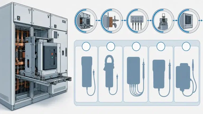
Secondary circuits must be verified before site installation. Factory acceptance tests (FAT) and site acceptance tests (SAT) follow overlapping but distinct protocols.
Continuity and insulation:
Operational sequence:
Anti-pumping verification:
Interlock function:
Supervision and alarms:
Wiring verification:
Integration testing:
Interlock coordination:
Load testing:
Site commissioning catches installation errors that factory tests cannot: reversed control polarity, incorrect relay settings, external interlock wiring mistakes, or control power distribution faults.
Symptoms: Breaker trips without fault present, often during closing operation or motor start
Possible causes:
Diagnosis:
Symptoms: Close button pressed but breaker does not close, or closes sluggishly
Possible causes:
Diagnosis:
Symptoms: Breaker pumps repeatedly on fault, or refuses to close after single trip
Possible causes:
Diagnosis:
Symptoms: Protection relay misoperation, SCADA status incorrect, earthing switch interlock fails
Possible causes:
Diagnosis:
Frequent operations accelerate auxiliary contact wear:
Critical breakers require dual trip coils:
SCADA-controlled breakers need additional supervision:
Secondary circuit quality separates reliable breakers from maintenance burdens. When evaluating suppliers:
Check auxiliary contact ratings: Some manufacturers provide 3 A contacts when application requires 6 A—premature failure results.
Verify anti-pumping implementation: Ask for detailed circuit diagrams showing relay type and seal-in logic.
Examine interlock flexibility: Can the breaker accommodate both electrical and mechanical key interlocks without custom modification?
Review supervision capabilities: Modern designs offer trip circuit supervision, spring status monitoring, and control voltage alarms as standard—older designs require retrofitting.
Confirm FAT test protocol: Does the manufacturer’s standard FAT include anti-pumping verification, contact sequencing measurement, and insulation testing?
XBRELE vacuum circuit breakers include comprehensive secondary circuit packages engineered for reliable operation across utility, industrial, and renewable energy applications. Our standard designs incorporate trip circuit supervision, dual-relay anti-pumping protection, and configurable interlock contact arrangements. Complete secondary circuit documentation, FAT reports, and commissioning support ensure installations meet both safety standards and operational requirements. Learn more in our vacuum circuit breaker manufacturer guide.
External Reference: IEC 62271-100 test and operating requirements are available on the IEC publication page: IEC 62271-100.
Q1: What is the difference between a trip circuit and a close circuit in a vacuum circuit breaker?
A: Trip circuits energize a coil that releases the mechanism’s trip latch, allowing opening springs to separate the contacts. Close circuits charge stored energy (spring or capacitor) then release it to drive contacts closed. Trip circuits prioritize fail-safe reliability, while close circuits incorporate anti-pumping and interlock protection.
Q2: Why do VCBs need anti-pumping protection?
A: Without anti-pumping protection, a breaker can repeatedly close onto a fault if the close command remains active. This “pumping” action subjects the mechanism to extreme mechanical shock, potentially destroying the spring mechanism or welding contacts. Anti-pumping circuits require the close command to reset before permitting another close attempt.
Q3: How many auxiliary contacts does a typical vacuum circuit breaker provide?
A: Most medium-voltage VCBs include 6–12 auxiliary contacts as standard (mix of “a” normally open and “b” normally closed contacts), expandable to 20+ contacts with additional auxiliary contact blocks. Contacts typically handle 5–10 A at control voltage.
Q4: What is trip circuit supervision and why is it necessary?
A: Trip circuit supervision continuously monitors the integrity of the trip coil circuit using a low-current relay or microprocessor-based system. If the circuit develops an open or high-resistance fault, supervision alarms alert operators before a protection operation fails. This prevents situations where the breaker cannot trip during a fault.
Q5: Can electrical interlocks be bypassed for emergency operations?
A: While physically possible, bypassing electrical interlocks creates severe safety risks and typically violates safety standards. Emergency procedures should use pre-engineered “forced operation” modes with supervisor authorization and additional safeguards—never field modifications that defeat interlocks.
Q6: What happens if control voltage drops below the rated value during operation?
A: Trip coils may fail to operate below 70% rated voltage, while close coils exhibit slow or incomplete operation below 80% rated voltage. Control voltage monitoring relays typically alarm at 85% to provide warning before operational failures occur. Critical applications may auto-trip the breaker on low voltage to avoid partial-stroke damage.
Q7: How is auxiliary contact sequencing verified during commissioning?
A: Commissioning engineers use simultaneous recording of main contact position (via travel measurement) and auxiliary contact state transitions (via logic analyzer or relay test set). Timing measurements are compared to manufacturer’s type test data—typically “a” contacts close 5–15 ms after main contact touch, and “b” contacts close 3–10 ms before main contact separation.