Need Full Specifications?
Download our 2025 Product Catalog for detailed drawings and technical parameters of all switchgear components.
Get Catalog
Download our 2025 Product Catalog for detailed drawings and technical parameters of all switchgear components.
Get Catalog Download our 2025 Product Catalog for detailed drawings and technical parameters of all switchgear components.
Get Catalog

Check 50Hz and60Hz transformer compatibility using voltage-to-frequency ratio, rated current, taps, losses, impedance, auxiliaries and downstream equipment requirements.
Whether a transformer can move between a 50 Hz and a 60 Hz supply depends on which direction it is moving, what it was originally rated for, and what sits on either side of it. It is not a single yes-or-no property. A unit built and nameplated for 60 Hz is the case that most often goes wrong when it is dropped into a 50 Hz network; a unit built for 50 Hz placed on a 60 Hz network is the more forgiving direction, but forgiving is not the same as approved. Between those two extremes sits a third case: a transformer that carries a genuine dual 50/60 Hz rating, with manufacturer-declared operating conditions at both frequencies.
The first thing to settle is what the transformer does and does not do. It transforms voltage. It does not transform frequency. Hammond Power Solutions states the point plainly in its 50/60 Hz definition FAQ: Transformers cannot change frequency, the primary frequency equals the secondary frequency. A 50 Hz sine wave entering the primary leaves the secondary as a 50 Hz sine wave, at whatever voltage the turns ratio dictates. Nothing inside the tank or the cast-resin enclosure generates a new frequency.
That single fact reframes the whole compatibility question. If the load needs 60 Hz and the site supplies 50 Hz, no transformer selection will fix it; a motor-generator set, a static frequency converter or a different machine design will. The transformer question is narrower and more answerable: given the frequency the site actually supplies, is this particular transformer allowed to run at that frequency, at the voltage and current it will see?
Nameplates carry frequency alongside voltage, kVA, connection and temperature rise, and the mark matters in three distinct ways.
A transformer marked for 50 Hz only was designed, and its magnetic circuit dimensioned, around 50 Hz. A transformer marked 60 Hz only was designed around 60 Hz. A transformer marked 50/60 Hz states that the manufacturer has qualified the same unit at both frequencies, which normally implies a declared rating at each — not necessarily identical kVA, and not necessarily the same tap position.
Hammond Power Solutions, in its frequency FAQ, gives directional guidance that matches the physics: 60 Hz-rated units should not be used on a 50 Hz supply because of core saturation, increased losses and higher temperature, while 50 Hz designs can be operated on 60 Hz. That is a statement about the magnetic core’s loading, and it is the right starting point. It is not a blanket approval of a complete installation, because the transformer is only one item in a chain that also contains cooling fans, control relays, contactor coils and the load itself.
So the practical order of checks is: read the nameplate frequency, read whether both frequencies are declared, then look at the voltage the supply will actually deliver at that frequency.
The core is the part of the transformer that cares most about frequency, and it cares through a ratio rather than through frequency alone.
For a sinusoidal supply, the induced emf in a winding follows the standard relation E ≈ 4.44 f N A Bmax, where f is frequency, N is turns, A is the effective core cross-section and Bmax is the peak flux density in the core. Rearranged, Bmax ≈ V / (4.44 f N A). For a finished winding on a finished core, N and A are fixed. Peak flux density is therefore proportional to volts per hertz.
That ratio is what the design was built around. At its rated voltage and rated frequency, the transformer sits at a peak flux density its designer chose — high enough to use the core efficiently, low enough to stay off the saturated part of the magnetisation curve, with margin for supply overvoltage and waveform distortion.
Change the frequency and hold the voltage, and the ratio moves:
The 20 percent increase is the whole reason the 60-to-50 direction is the dangerous one. Pushing peak flux density up by a fifth can take a core that was comfortably below the knee of its magnetisation curve into the region where a small additional voltage produces a large additional magnetising current. The consequences are not subtle: a distorted, peaky magnetising current, a sharp rise in no-load loss, audible noise, and heating in the core and the surrounding structure.

The ratio is a trend indicator, not a saturation verdict. Two units with the same V/f change can behave very differently, depending on how much headroom the original design carried, how much supply overvoltage the site actually delivers (a 50 Hz network running at plus 10 percent is a further 10 percent on top of the already increased ratio), how distorted the supply waveform is (the flux waveform depends on the time integral of applied voltage, so a fundamental-frequency V/f ratio does not capture every waveform effect), and how the core behaves at the resulting temperature. That is why the honest answer to whether a specific 60 Hz unit will survive at 50 Hz is a manufacturer’s calculation on the actual design, not an extrapolation from the ratio alone.
There is an obvious-looking workaround: if V/f is the problem, lower the voltage along with the frequency. On paper the arithmetic works.
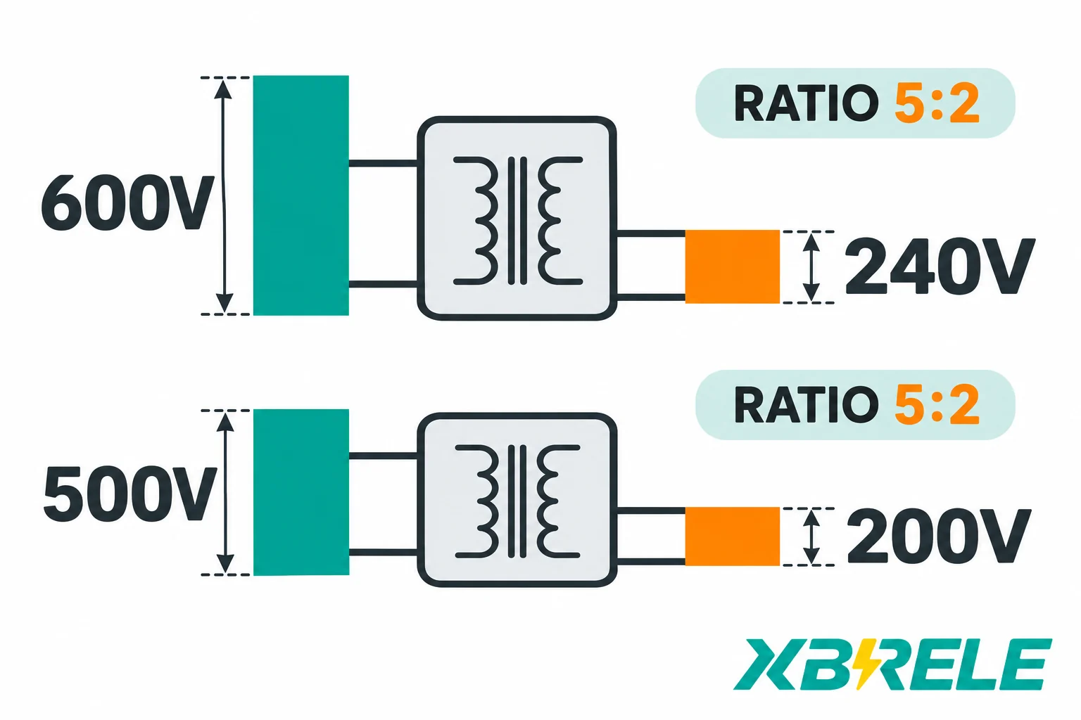
Take an illustrative unit rated 600 V at 60 Hz. Its rated V/f is 10 volts per hertz. Run it at 50 Hz and 500 V and the ratio is again 10 volts per hertz. For the same turns and core under an ideal sinusoidal assumption, the calculated flux-density demand is unchanged. This removes the arithmetic V/f increase; it does not prove the whole operating point is acceptable.
What has actually changed is everything downstream of the core.
The turns ratio is untouched, so the secondary voltage falls by the same five-sixths. A transformer with a 600/240 V ratio, fed at 500 V instead of 600 V, will produce 200 V at its secondary, not 240 V. If the load needs its original voltage, the workaround has already failed.
The current rating is a property of the winding conductors and their cooling, not of the core, so in principle the unit can still carry its rated current. Apparent power is voltage times current, so at five-sixths of the voltage and full current the throughput is five-sixths of the nameplate kVA. That is arithmetic, not an approved rating. Nothing about that calculation has verified temperature rise, loss density, insulation stress or the suitability of the reduced-voltage point for the load.
The dielectric design is unchanged and, at reduced voltage, less stressed — that part is true. But the load is not. The familiar voltage-squared induction-motor torque approximation compares conditions at the same frequency and slip; it cannot be used alone to compare 240 V/60 Hz with 200 V/50 Hz. The motor’s V/f, speed, load torque, cooling and permitted current must be checked together. Contactors with AC coils may not pick up reliably. Timers and instruments referenced to voltage may misoperate. Control power supplies may drop out. Each of these is a load-side problem created by a fix applied on the transformer side.
Taps deserve their own warning. An off-load tap changer alters the number of effective turns on one winding, which changes the volts per turn and therefore changes flux density for a given primary voltage. A tap can genuinely bring V/f back into range for a specific site voltage, and that is a legitimate part of a manufacturer’s study. But a tap changes turns. It does not change frequency, it does not restore the original secondary voltage and the original throughput at the same time, and current capability, impedance and loss distribution require confirmation at the selected tap. A tap is not a frequency conversion, and a tap table is not a derating certificate.
Clearing the core is one check out of several. The others are thermal and electromagnetic, and they do not follow the same rules.

Core loss depends on both frequency and flux density as well as material and waveform. At constant voltage a frequency change also changes flux, so it is insufficient to consider frequency in isolation. Winding resistance loss depends on current and conductor temperature, while additional eddy and structural stray losses have their own frequency and field dependence. The loss components need a design-specific assessment at the target operating point; they do not all follow a single frequency multiplier.
The consequence is that there is no general rule of the form efficiency falls by X percent or temperature rise rises by Y kelvin when the frequency changes. The total loss at the new operating point has to be established for that design, and then compared against the cooling available at that point.
Cooling auxiliaries may have separate frequency limits. A line-fed induction fan motor can change speed when frequency changes; its developed torque, current, available airflow and absorbed power must then be checked on the fan/system curves and motor rating. An electronically controlled or DC fan may behave differently. A higher nominal speed does not by itself prove adequate or permissible cooling. Fan and pump motors, control transformers, relays and contactor coils each need their own compatibility confirmation.
Impedance moves as well. For a preliminary linear leakage-inductance model, X = 2πfL changes with frequency. DC winding resistance mainly follows material and temperature, while effective AC resistance and additional losses also depend on frequency and conductor geometry. Percent impedance on a fixed kVA base therefore changes when the frequency changes, and the X/R ratio changes with it. That has three practical consequences: voltage regulation under load shifts, short-circuit current at the secondary shifts because it is driven by the impedance, and protection coordination studies that assumed one impedance value may no longer describe the same installation. A percentage impedance quoted at 60 Hz should not be silently reused at 50 Hz; ask for the value recalculated on the declared base at the target frequency.
The transformer passes frequency through unchanged, so whatever is on the secondary sees the grid’s frequency — and that is where a surprising number of export problems actually live.
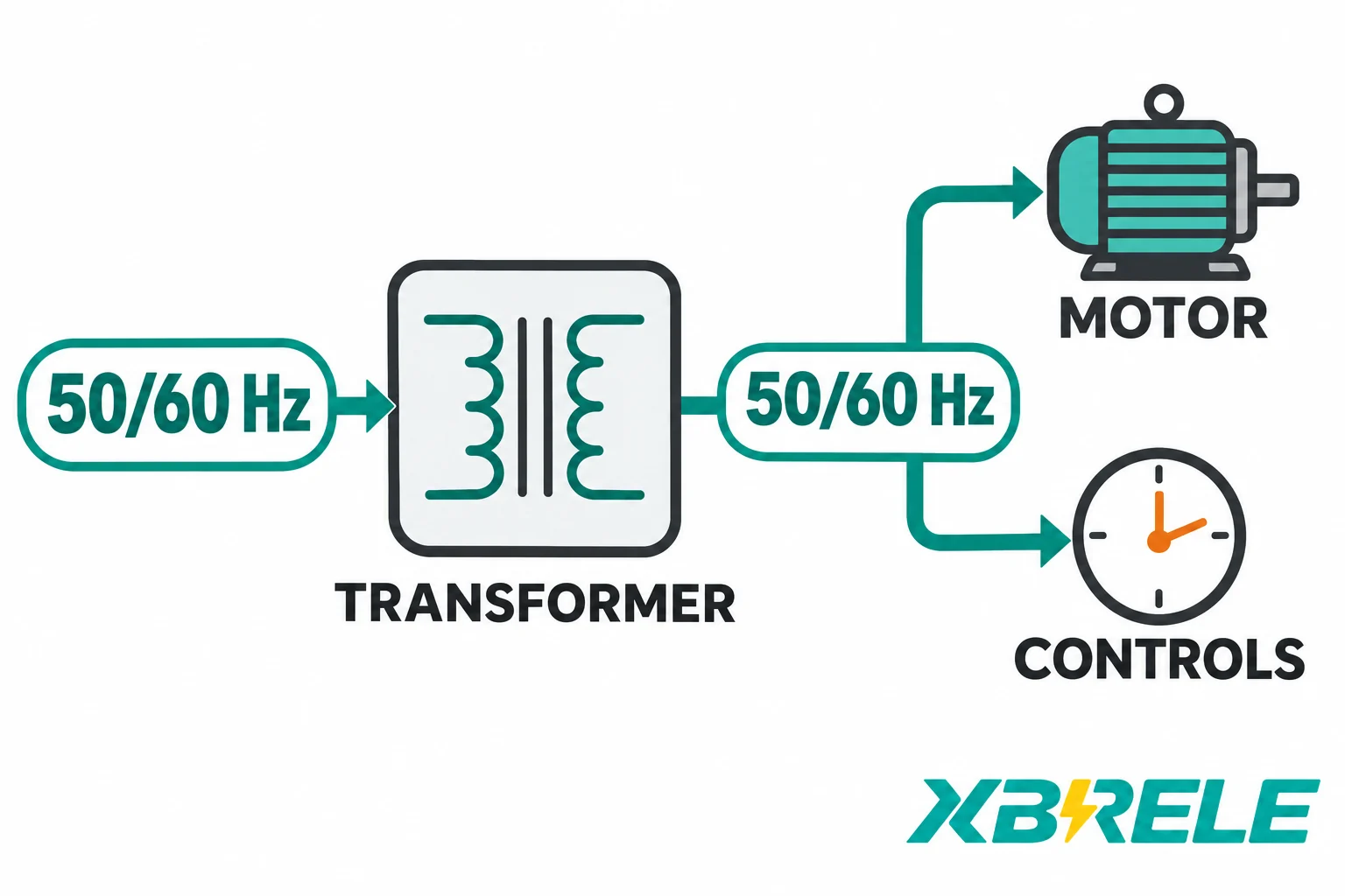
For induction motors, synchronous speed is set by frequency and pole count: n = 120 f / p. A four-pole motor runs at 1500 rpm synchronous at 50 Hz and 1800 rpm at 60 Hz. The actual rotor speed also depends on slip and drive control; an unregulated line-fed machine can therefore run at a different speed. Whether that is acceptable depends entirely on the driven load. For a centrifugal pump or fan, absorbed power varies roughly with the cube of speed, so a 20 percent speed increase asks for about 73 percent more power — the motor and the coupling may not be able to supply it. For a constant-torque load, the shaft power demanded rises 20 percent at the higher speed. For any positive-displacement pump or conveyor, check the driven equipment’s permitted speed, process duty and mechanical limits as well as motor loading.
Torque capability itself depends on the motor’s own volts per hertz, which is now a separate question from the transformer’s. If the supply voltage and the motor rating move together with frequency, the motor’s magnetic design stays near its rated point. If the frequency changes while the voltage does not, the motor’s V/f moves too. Its flux, torque-speed characteristic and allowable load then require a motor-specific assessment, including slip and cooling.
Variable-frequency drives complicate the picture in a different way, and often helpfully. A drive rectifies the incoming supply and synthesises its own output frequency, so the motor after the drive runs at whatever the drive commands. But the drive’s input stage still sees the grid frequency, its input current rating and its DC-bus ripple are specified against a particular input frequency, and the transformer feeding the drive carries the drive’s harmonic currents, which have their own loss and heating effects in windings and structural parts.
Then there are the small loads that quietly count cycles. A supply-cycle-based clock calibrated for 50 Hz would run 20 percent fast at 60 Hz; one calibrated for 60 Hz would run at five-sixths speed, about 16.7 percent slow, at 50 Hz. This does not describe independently timed electronic devices. AC coils and their magnetic circuits can have different pickup, holding and thermal behaviour at another frequency. Confirm their stated voltage/frequency duty rather than assuming a universal current or pickup result. Small control transformers have their own V/f. Every one of these is a separate identity with its own frequency rating, and every one of them sits downstream of a transformer that has already passed the frequency through untouched.
This is why the 50 Hz design on a 60 Hz supply is described as the favourable direction for the transformer and nothing more. Electromagnetically the core is comfortable. That statement says nothing about whether the fan motor, the control relay or the driven machine has been checked.
The table below condenses the four cases into a provisional assessment. Provisional is the operative word: every row ends in a confirmation step, because the core ratio tells you only what to investigate.
| Case | Provisional core assessment | Main system issues | What to obtain before commitment |
|---|---|---|---|
| Unit carries a genuine dual 50/60 Hz rating | Both operating points designed and declared | Rated current, losses and temperature rise may differ between frequencies; tap schedules may differ | The dual-rating schedule: kVA, voltage, current, temperature rise and applicable taps at each frequency |
| 60 Hz-only unit on a 50 Hz supply at nameplate voltage | V/f rises 20 percent; saturation risk, higher no-load loss and core heating | Magnetising current distortion, noise, core and structure heating, possible protection maloperation | A manufacturer’s written assessment of the actual design at the target frequency, or a redesign. Not an internal engineering judgement |
| 60 Hz-only unit on a 50 Hz supply with voltage reduced to hold V/f | Core loading restored by arithmetic | Secondary voltage falls to five-sixths; throughput falls to five-sixths at rated current; motor torque, coil pick-up and control supplies all affected | A written rating at the reduced-voltage point covering losses, temperature rise and permitted current, plus a load-by-load voltage tolerance check |
| 50 Hz-only unit on a 60 Hz supply at nameplate voltage | V/f falls to five-sixths; the favourable direction for the core | No-load loss may rise; noise may change; fan motors and controls may have incompatible frequency duties; line-fed motor and driven-load speed can change | Loss and temperature-rise data at 60 Hz, auxiliary component frequency ratings, and a load speed and torque review |
The inputs that turn this table into a real answer are consistent across all four rows: the nameplate rating schedule including frequency, the tap table and which taps apply at which frequency, the supply voltage and frequency tolerance the site actually delivers, the waveform and harmonic environment, the duty cycle and ambient conditions, the cooling arrangement and the frequency rating of every fan and auxiliary, a load list with the frequency-sensitive items identified, and approved no-load loss, load loss and impedance values at the target frequency on a declared base. Test certificates are useful, but they are evidence of what was tested and at what frequency — not a substitute for a statement about the operating point you intend to use.
Two contrasting projects show how differently the same question resolves.
A packaged skid destined for a 60 Hz region is assembled from 50 Hz cast-resin dry-type transformers already in the supplier’s catalogue, because that was the available build. Electromagnetically this is the easy direction: the fixed-turns sinusoidal V/f demand is lower at the stated voltage. Confirm the transformer losses and thermal duty, then review the auxiliary and load side — fans, control transformers, contactor coils, relay coils, and the motors on the pumps, all of which must be confirmed for 60 Hz, and any motor driving a centrifugal load must be checked for the extra shaft power at the higher speed. The transformer study is a loss and temperature-rise confirmation at 60 Hz; the rest of the package is a component-by-component frequency review.
A second project has a 60 Hz-rated unit in stock and a site that supplies 50 Hz. The tempting move is to run it at five-sixths of its rated voltage and call the core problem solved. It is not solved, it is relocated. The secondary now delivers five-sixths of its design voltage to a load that was specified for the original value, the throughput at rated current is five-sixths of nameplate, and none of that arithmetic has been approved by anyone. The right move is to send the actual design data — rating, taps, core and winding details, loss and impedance values, cooling arrangement — to the manufacturer and ask for a written position either on operation at 50 Hz at a stated voltage and current, or on the redesign that would make it valid.
For XBRELE’s part, the actual cast-resin dry-type catalogue carries no-load and load loss information at several reference temperatures along with ventilation and enclosure guidance. Catalogue loss rows should be treated as indicative rather than as the agreed value for an application at a different supply frequency, particularly where the tables are being read across different reference temperatures. For an export project, the useful step is to state the target frequency, the supply voltage and its tolerance, the required throughput, the load list and the ambient, and ask for the loss, impedance, temperature-rise and cooling data at that operating point. The dry-type catalogue entry is at Power Distribution Transformers — Dry Type Transformer, and a concrete project brief can be submitted through the contact page. A dual 50/60 Hz rating should be confirmed for the specific unit rather than assumed from a catalogue page.
Not by itself. A dual marking should be backed by a declared rating at each frequency — voltage, current, kVA, temperature rise and the tap positions that apply at each — because the same core and windings can produce different permissible outputs at 50 Hz and 60 Hz. Where only a frequency range is printed without a rating schedule, treat the marking as a statement of intended application rather than as evidence that both operating points have been qualified, and ask for the schedule before you commit a design.
No. An ordinary two-winding transformer transfers energy through a shared magnetic flux, and that flux alternates at whatever frequency the supply imposes, so the secondary frequency equals the primary frequency. Changing frequency requires a machine or a power-electronic converter — a motor-generator set or a static frequency converter — placed between the supply and the load. A transformer can change the voltage that accompanies that frequency, but it cannot change the frequency itself.
Because derating addresses the thermal question while leaving the magnetic one open. Lowering the throughput reduces winding loss and therefore temperature rise, but it does not reduce peak flux density, which is set by voltage and frequency and is independent of how much current the load draws. A 60 Hz core at 50 Hz and full voltage still sees a 20 percent higher V/f whether it carries 100 percent or 50 percent of its rated current, and it can saturate at no load just as readily as under load. Derating is a thermal measure; the saturation problem needs a voltage, frequency or design change.
The core is usually fine, but always is too strong a word. At the same voltage, a 50 Hz design on 60 Hz runs at five-sixths of its design flux density, which is magnetically comfortable. What is not automatically covered is the rest of the unit and the installation: the loss components and acoustic behaviour require confirmation, auxiliaries retain their own frequency ratings, and line-fed motor speed and driven-load power can change. A contactor has no rotating speed, and controlled motor systems may maintain the original speed. Check the auxiliaries and the load, and get loss and temperature-rise data at 60 Hz, rather than relying on the direction of the core ratio alone.