Need Full Specifications?
Download our 2025 Product Catalog for detailed drawings and technical parameters of all switchgear components.
Get CatalogDownload our 2025 Product Catalog for detailed drawings and technical parameters of all switchgear components.
Get CatalogDownload our 2025 Product Catalog for detailed drawings and technical parameters of all switchgear components.
Get Catalog

Size VFD transformers with derating, THDi, K-factor, harmonic heating, and insulation checks for variable-speed systems.
Variable frequency drives draw current in pulses rather than smooth sinusoidal waves—and this fundamental difference forces a complete rethink of transformer sizing. A 500 kVA transformer feeding VFD loads can trip on thermal overload at just 65% apparent capacity. The disconnect between nameplate ratings and real-world performance catches many specifiers off guard.
The problem originates at the VFD’s input stage. Six-pulse diode rectifiers—found in over 90% of industrial drives—conduct current only during brief peaks of each AC half-cycle. This creates harmonic currents at predictable frequencies that standard transformer ratings simply don’t account for.
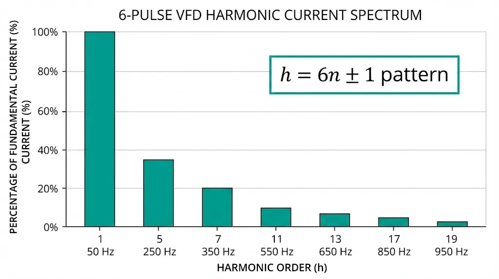
VFDs convert incoming AC power to DC through a rectifier bridge, then synthesize variable-frequency output for motor control. This nonlinear conversion draws current in discrete pulses synchronized with DC bus capacitor charging. The resulting waveform contains the fundamental 50 or 60 Hz component plus harmonics following the h = 6n ± 1 pattern.
Typical 6-Pulse VFD Harmonic Spectrum:
| Harmonic Order | Frequency (50 Hz System) | Typical Magnitude (% of Fundamental) |
|---|---|---|
| 5th | 250 Hz | 25–40% |
| 7th | 350 Hz | 15–25% |
| 11th | 550 Hz | 8–12% |
| 13th | 650 Hz | 5–9% |
| 17th | 850 Hz | 3–6% |
Combined total harmonic distortion in current (THD-I) typically ranges from 35% to 80% for standard six-pulse drives. Some facilities with multiple smaller VFDs see THD-I exceeding 90%.
According to IEEE 519-2022 (Recommended Practice for Harmonic Control), voltage distortion at the point of common coupling must remain below 5% THD-V for general systems and below 3% for sensitive equipment. Current distortion limits depend on the ratio of short-circuit current (ISC) to load current (IL), with stricter limits applying to weaker systems where ISC/IL < 20.
Multi-pulse configurations reduce but never eliminate harmonics. Twelve-pulse drives achieve THD-I of 8–15%, while eighteen-pulse designs reach 5–8%. Active Front End (AFE) drives push below 5% THD-I but carry significant cost premiums. Standard six-pulse drives remain dominant, making harmonic-aware transformer selection essential.
Nameplate transformer ratings assume sinusoidal current flow. Harmonic currents create additional losses that standard ratings ignore entirely.
Eddy Current Losses in Windings
Eddy current losses scale with both current magnitude squared and harmonic order squared. The 5th harmonic at 30% magnitude generates 0.30² × 5² = 2.25× the loss contribution per unit current compared to fundamental frequency. The 7th harmonic at 20% magnitude adds 0.20² × 7² = 1.96× additional losses.
Eddy current losses increase proportionally to the square of harmonic order: PEC ∝ Ih² × h², where Ih represents harmonic current magnitude and h represents the harmonic order. A 5th harmonic current of 20% fundamental magnitude contributes 25× more eddy current losses than its apparent magnitude suggests.
Skin Effect in Conductors
High-frequency currents crowd toward conductor surfaces, reducing effective cross-sectional area. At 350 Hz (7th harmonic), skin depth in copper decreases to approximately 3.5 mm compared to 9.4 mm at 50 Hz fundamental. This increases AC resistance by factors of 1.5 to 3.0 at higher harmonic orders.
Stray Losses in Structural Components
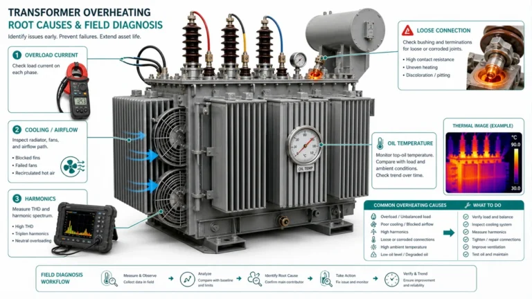
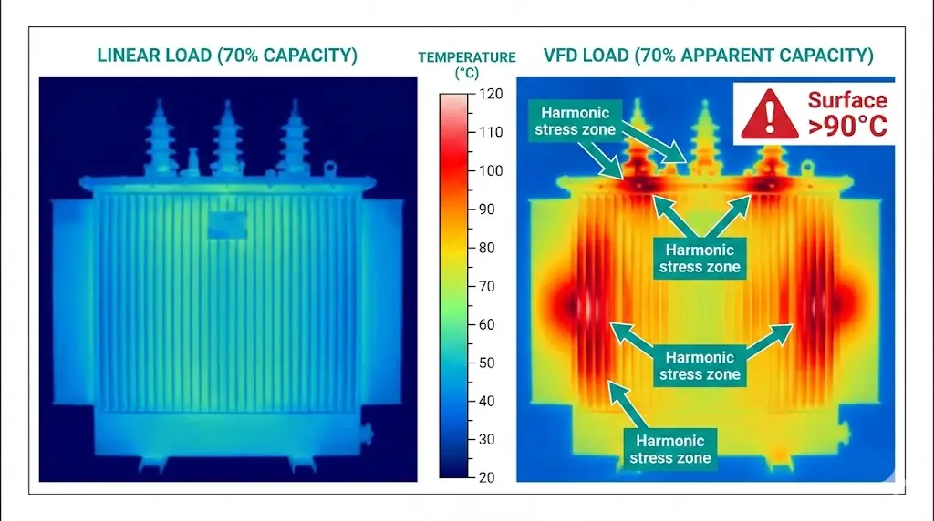
Harmonic flux links with tank walls, core clamps, and tie rods. Field thermal imaging has revealed hotspots exceeding 120°C on standard transformer tanks when serving VFD loads above 60% nameplate capacity without proper K-factor rating. These localized temperatures escape detection by standard winding temperature sensors.
| Harmonic Order | Frequency (50 Hz) | Relative Eddy Loss Factor (h²) |
|---|---|---|
| 1 (Fundamental) | 50 Hz | 1× |
| 5th | 250 Hz | 25× |
| 7th | 350 Hz | 49× |
| 11th | 550 Hz | 121× |
| 13th | 650 Hz | 169× |
A transformer showing 70% load on a standard ammeter may experience internal losses equivalent to 95–110% loading when harmonics are present. This explains premature thermal trips that puzzle maintenance teams expecting adequate headroom.

[Expert Insight: Field Observations on Thermal Stress]
- Transformers at 80% nameplate capacity with VFD loads consistently run 15–25°C hotter than identical units serving linear loads
- Winding hotspot temperatures increase 8–15°C above predictions when THD-I exceeds 35%
- Insulation aging accelerates dramatically—every 10°C rise approximately halves life expectancy
- Audible buzzing at frequencies above normal 100/120 Hz hum indicates harmonic stress
K-factor quantifies a transformer’s ability to handle harmonic heating as a single derating metric. The calculation weights harmonic currents by frequency squared, reflecting the physics of eddy current loss generation.
K-factor calculation follows the formula: K = Σ(Ih)2 × h2, where Ih represents the per-unit harmonic current magnitude and h indicates the harmonic order. For six-pulse VFDs, characteristic harmonics occur at orders 5, 7, 11, 13, 17, and 19. A typical six-pulse VFD produces K-factors between 9 and 13, while twelve-pulse configurations generally yield K-factors of 4-6 due to cancellation of 5th and 7th harmonics.
Standard transformers are designed for K-1 (pure sinusoidal load). K-rated transformers incorporate specific design countermeasures:
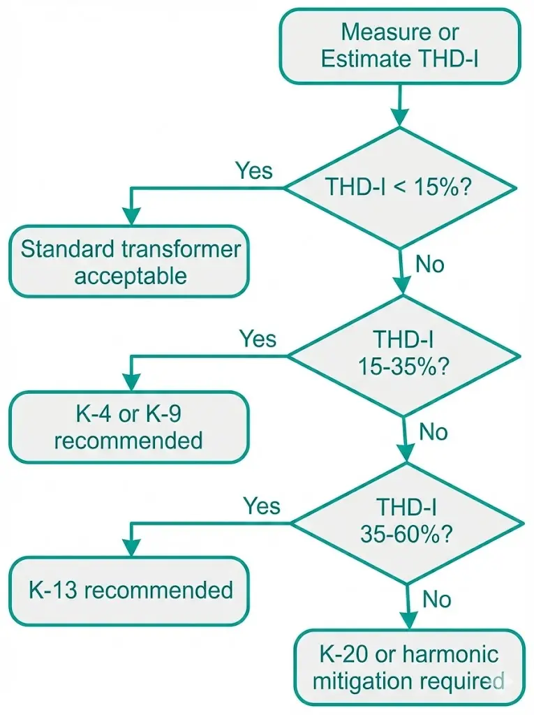
K-Factor Selection Matrix:
| K-Rating | Target THD-I Range | Typical Applications |
|---|---|---|
| K-1 | <5% | Linear loads only |
| K-4 | 15–25% | Office buildings, light commercial |
| K-9 | 25–40% | Mixed motor/VFD loads |
| K-13 | 40–60% | Heavy VFD populations, DC drives |
| K-20 | 60–80% | Severe nonlinear environments |
For facilities requiring harmonic tolerance without oil maintenance concerns, dry-type transformer designs offer K-rated options with vacuum-pressure impregnated or cast-resin insulation systems rated for Class H (180°C) operation.
When K-rated procurement isn’t feasible—retrofit situations, budget constraints, or moderate harmonic levels—derating standard transformers provides an alternative path.
IEEE C57.110 (Recommended Practice for Establishing Liquid-Immersed and Dry-Type Power and Distribution Transformer Capability When Supplying Nonsinusoidal Load Currents) establishes the methodology for calculating reduced capacity under harmonic loading.
Practical Derating Factors:
| Load Scenario | Typical THD-I | Approximate K-Factor | Derating Factor | Effective Capacity (500 kVA base) |
|---|---|---|---|---|
| Single large VFD (6-pulse) | 40–50% | K ≈ 8–10 | 0.80–0.85 | 400–425 kVA |
| Multiple small VFDs | 55–70% | K ≈ 13–18 | 0.68–0.75 | 340–375 kVA |
| VFDs + DC drives + welders | 75–90% | K ≈ 20–28 | 0.58–0.65 | 290–325 kVA |
Many engineers apply blanket 75–80% derating for VFD-heavy installations when detailed harmonic analysis isn’t available. This sacrifices capacity efficiency but provides thermal margin against premature failure.
Annual energy costs reflect efficiency differences substantially. A facility operating VFD-fed transformers 8,000 hours annually at $0.12/kWh experiences $2,400–$4,800 additional energy costs per 100 kW of connected VFD load when using improperly sized standard transformers versus properly specified K-rated alternatives.
[Expert Insight: Derating vs. K-Rating Economics]
- K-rated transformers carry 20–35% cost premium over standard equivalents
- A derated 630 kVA standard unit delivering 480 kVA effective may cost less than a 500 kVA K-13 unit
- However, the standard unit ages faster—expect 12–18 year service life versus 25–30 years for K-rated
- Total cost of ownership typically favors K-rated specification for >50% VFD load factor
Transformer selection for VFD installations follows four distinct approaches, each suited to specific project constraints.
Option 1: Derated Standard Transformer
Best for retrofit projects with moderate harmonics (K < 9) and constrained budgets. Expect 15–40% capacity reduction. Lower upfront cost but accelerated insulation aging risk.
Option 2: K-Rated Transformer Matched to Load Profile
Optimal for new installations with known VFD population. Full nameplate capacity remains available with designed thermal margins. The 20–35% cost premium pays back through extended service life and reduced energy losses.
Option 3: Isolation Transformer Per Drive
Appropriate for critical drives or sensitive upstream equipment requiring harmonic containment. Each VFD receives dedicated transformation with impedance matched for drive protection. High total cost and significant footprint, but maximum isolation.
Option 4: Standard Transformer Plus Harmonic Mitigation
Effective for existing transformer investments or IEEE 519 compliance at the point of common coupling. Mitigation options include:
| Selection Approach | Upfront Cost | Usable Capacity | Harmonic Mitigation | Space Required |
|---|---|---|---|---|
| Derated Standard | Low | 60–85% | None | Minimal |
| K-Rated Match | Medium-High | 100% | Built-in tolerance | Minimal |
| Drive Isolation | High | 100% per unit | Partial containment | Significant |
| Standard + Filter | Medium-High | 100% | Active reduction | Moderate |
Explore the complete range of power distribution transformers engineered for industrial harmonic environments, including K-rated dry-type and enhanced oil-immersed configurations.
Pre-commissioning and ongoing verification ensure transformer selection decisions translate into reliable field performance.
Pre-Installation Requirements
Conduct harmonic site surveys when existing VFDs operate on-site. Request harmonic spectrum data from drive manufacturers in IEEE 519 format. Calculate aggregate K-factor before finalizing transformer specifications.
Commissioning Checks
Deploy power quality analyzers capable of capturing current harmonics to at least the 25th order. Thermal imaging of transformer tanks, bushings, and cable terminations establishes baseline temperature distribution. Verify winding temperature rise within insulation class limits—Class F allows 115°C rise, Class H permits 150°C rise for dry-type units.
Warning Signs of Harmonic Stress
For installations comparing thermal performance under harmonic stress, oil-immersed transformers offer different heat dissipation characteristics than dry-type alternatives—particularly relevant where ambient temperatures exceed 40°C. Cooling class trade-offs should be validated against this ONAN/ONAF/OFAF guide.
XBRELE manufactures distribution transformers engineered for nonlinear load environments—including VFD-intensive manufacturing, data centers, and process industries where harmonic currents are unavoidable.
Engineering Capabilities:
Whether specifying new equipment or evaluating existing capacity under changing loads, technical consultation ensures the transformer matches real operating conditions—not just nameplate assumptions.
Contact XBRELE’s transformer specialists to discuss your VFD load profile and receive application-specific sizing guidance.
What K-factor rating do most VFD installations require?
Facilities with moderate VFD populations (THD-I between 30–50%) typically need K-9 or K-13 rated transformers. Twelve-pulse drive systems usually operate satisfactorily with K-4 ratings due to reduced 5th and 7th harmonic content.
How much capacity do I lose when derating a standard transformer for VFD loads?
Expect 15–40% capacity reduction depending on harmonic severity. A 500 kVA standard transformer serving six-pulse VFDs with 45% THD-I typically delivers only 350–425 kVA of usable capacity before reaching thermal limits.
Can passive filters eliminate the need for K-rated transformers?
Passive LC filters tuned to dominant harmonics (5th and 7th) reduce THD-I by 50–70%, often bringing effective K-factor below 4. This allows standard transformers to operate without significant derating in many applications, though filter maintenance adds ongoing cost.
Why does my transformer run hot even at 70% apparent load?
Harmonic currents create eddy current and stray losses invisible to standard ammeters. A transformer showing 70% load may experience internal heating equivalent to 95–110% loading when serving VFD loads with THD-I exceeding 35%.
What’s the typical cost difference between standard and K-13 transformers?
K-13 rated units carry 25–35% price premiums over equivalent standard transformers. However, K-rated designs deliver full nameplate capacity under harmonic loads and typically achieve 25–30 year service life versus 12–18 years for standard units in VFD service.
How do I verify transformer performance after installation?
Deploy power quality analyzers measuring current harmonics through the 25th order during commissioning. Conduct thermal imaging to identify hotspots on tank walls, bushings, and terminations. Trend winding temperatures versus load percentage monthly during the first year of operation.
Do 18-pulse VFDs eliminate transformer harmonic concerns entirely?
Eighteen-pulse configurations reduce THD-I to 5–8%, allowing K-4 rated or even standard transformers in most applications. However, the phase-shifting transformer arrangement required for 18-pulse operation adds cost and footprint that may offset K-rated transformer premiums.