Need Full Specifications?
Download our 2025 Product Catalog for detailed drawings and technical parameters of all switchgear components.
Get CatalogDownload our 2025 Product Catalog for detailed drawings and technical parameters of all switchgear components.
Get CatalogDownload our 2025 Product Catalog for detailed drawings and technical parameters of all switchgear components.
Get Catalog
A protection relay detects a fault in 20 milliseconds. It sends a trip command. The circuit breaker does nothing.
This scenario—where the trip circuit fails silently—ranks among the most dangerous conditions in medium-voltage switchgear. The fault persists, equipment sustains arc damage, and what should have been routine protection becomes a major incident investigation.
Trip circuit supervision prevents this outcome. By continuously verifying the integrity of every component between the protection relay and the trip coil, TCS transforms hidden failures into visible alarms. A broken wire, a corroded terminal, a failed coil winding—any open circuit triggers an alarm days or weeks before a fault ever tests the protection system.
Close circuit monitoring applies identical principles to the breaker closing circuit, ensuring restoration and auto-reclosing sequences execute reliably.
This guide covers the three primary TCS scheme architectures, provides step-by-step testing procedures for commissioning and maintenance, and delivers systematic troubleshooting methods for the nuisance alarms that plague many installations. Understanding these supervision circuits is fundamental to maintaining reliable protection for vacuum circuit breaker installations and other MV switchgear.
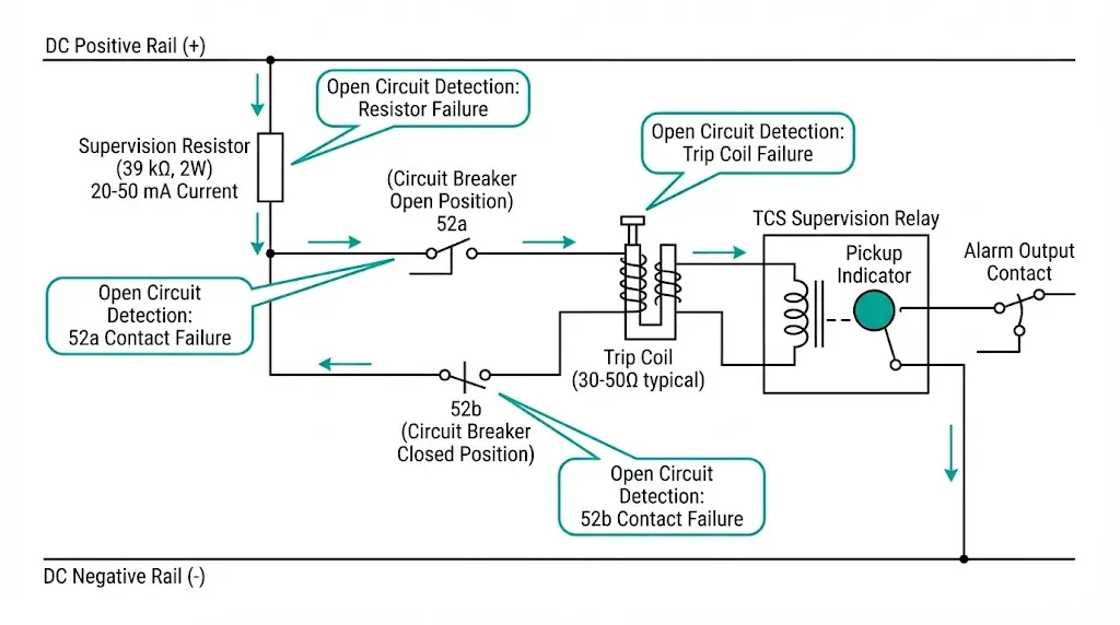
Trip circuit supervision continuously monitors the complete path from DC supply to trip coil, alarming immediately when any series component fails. This proactive detection prevents the catastrophic scenario where a protection relay operates correctly but the breaker never receives its trip command.
The supervision current—typically 20-50 mA DC—flows through the entire trip circuit without operating the breaker. This current remains well below the trip coil pickup threshold, which ranges from 100-200 mA for most medium-voltage breakers. When any element opens, supervision current drops to zero and the TCS relay alarms.
Components under continuous monitoring include:
| Failure Type | Common Cause | TCS Detection Speed |
|---|---|---|
| Open circuit | Broken wire, loose terminal | Immediate (< 2 seconds) |
| DC supply loss | Battery failure, blown fuse | Immediate |
| Trip coil open | Winding failure, thermal damage | Immediate |
| High resistance | Corroded connection | Voltage-dependent |
| Auxiliary contact fault | Mechanical wear, contamination | State-dependent |
Field data from commissioning records across industrial substations reveals that wiring termination failures represent approximately 35-40% of detected trip circuit faults. Thermal cycling, vibration from adjacent equipment, and moisture ingress accelerate connection degradation. Modern TCS relays provide time-stamped fault logging per IEEE PSRC guidelines, enabling maintenance teams to correlate supervision alarms with environmental conditions.
Scheme selection depends on criticality, available auxiliary contacts, and whether the installation uses discrete relays or integrated numerical protection.
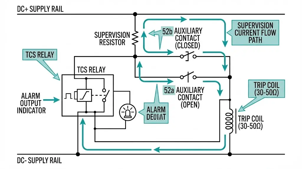
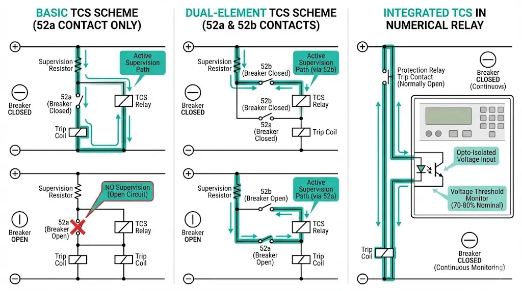
The simplest configuration monitors the trip circuit only when the breaker is closed. A supervision resistor connects in series with the trip coil, and current flows through the normally-open 52a auxiliary contact.
Resistor sizing example for 110V DC system:
The critical limitation: when the breaker trips open, the 52a contact opens and supervision stops. A trip circuit fault occurring while the breaker is open remains undetected until the next close-trip cycle.
This configuration provides continuous supervision regardless of breaker position. The scheme uses both the normally-open 52a contact and normally-closed 52b contact to maintain a supervision path in both states.
The dual-element scheme detects auxiliary contact failures that single-element schemes miss. If the 52b contact fails to close when the breaker opens, supervision current drops and an alarm initiates. This scheme is standard practice for critical feeders and transmission-class breakers.
Modern IEC 61850-compliant relays incorporate TCS as a standard function. Instead of injecting supervision current through an external relay, the protection device monitors trip circuit voltage through opto-isolated inputs.
Operating characteristics:
No external supervision relay is required, reducing panel wiring and potential failure points.
| Feature | Basic (52a) | Dual-Element | Integrated |
|---|---|---|---|
| Supervision when OPEN | No | Yes | Yes |
| Supervision when CLOSED | Yes | Yes | Yes |
| External relay needed | Yes | Yes | No |
| Aux contacts required | 1 NO | 1 NO + 1 NC | 1 NO minimum |
| Best application | Non-critical | Critical feeders | New installations |
[Expert Insight: Scheme Selection in Practice]
- For 11kV distribution feeders with auto-reclosing, dual-element schemes justify the additional auxiliary contact cost
- Retrofit projects often use basic schemes due to limited auxiliary contact availability on legacy breakers
- Integrated TCS eliminates the supervision resistor thermal derating concerns in high-ambient installations
- Always verify auxiliary contact overlap timing before specifying dual-element schemes
Close circuit monitoring uses identical scheme architectures but supervises the path to the closing coil rather than the trip coil. The critical difference lies in anti-pump relay interaction.
Anti-pump circuits prevent repeated closing attempts if the close command remains asserted after the breaker closes. The anti-pump relay contact opens after close initiation, breaking the close coil circuit. This normal protective function can trigger nuisance alarms if close circuit supervision reacts before the anti-pump relay resets.
Solution: Configure supervision with a time-delayed reset of 2-5 seconds after close operations. This delay allows anti-pump relay contacts to return to their normal state before supervision re-evaluates circuit integrity.
| Aspect | Trip Circuit | Close Circuit |
|---|---|---|
| Failure impact | Protection failure | Restoration delay |
| Priority level | Critical | Important |
| Anti-pump interaction | No | Yes—requires delayed reset |
| Typical supervision | Always recommended | Application-dependent |
Close circuit failures delay restoration sequences and compromise auto-reclosing schemes. While less critical than trip circuit failures, close circuit monitoring becomes essential for feeders serving hospitals, data centers, or continuous process industries where restoration speed directly impacts operations.
Commissioning and periodic maintenance require systematic verification that TCS detects faults at every potential failure point. Testing must confirm both alarm generation on fault conditions and absence of interference with actual trip operations.
Procedure:
Acceptance criteria summary:

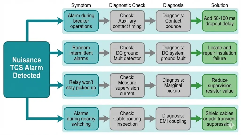
Nuisance alarms erode operator confidence and lead to alarm fatigue—a dangerous condition where legitimate alarms get dismissed. Systematic troubleshooting eliminates false positives while preserving genuine supervision.
Symptom: Momentary TCS alarm during trip or close operations, resetting within 1-2 seconds.
Cause: Mechanical auxiliary contacts exhibit bounce during state transitions. If the 52a contact opens before the 52b contact closes during a trip operation, a brief supervision gap occurs.
Fixes:
Symptom: Intermittent TCS alarms that correlate with switching operations elsewhere in the DC system.
Cause: Undetected ground faults on ungrounded DC systems create sneak current paths that affect supervision voltage levels when other circuits switch.
Fixes:
Symptom: TCS relay fails to pick up reliably or drops out on minor DC voltage fluctuations.
Cause: Supervision resistor value too high, resulting in marginal pickup conditions.
Fixes:
Symptom: TCS alarms during switching operations elsewhere in the substation, with no correlation to breaker position or DC system faults.
Cause: Electromagnetic interference from switching transients couples into supervision wiring.
Fixes:
| Symptom | First Check | Likely Fix |
|---|---|---|
| Alarm during operations | Aux contact timing | Add 50-100 ms delay |
| Random intermittent alarms | DC ground fault detector | Locate and repair ground |
| Relay won’t stay picked up | Supervision current level | Reduce resistor value |
| Alarms during nearby switching | Cable routing | Shield or re-route cables |
[Expert Insight: Field Troubleshooting Shortcuts]
- Carry a clamp-on milliamp meter—measuring actual supervision current immediately identifies marginal pickup conditions
- Intermittent alarms often correlate with temperature; check morning vs afternoon alarm patterns
- Before replacing components, flex cables gently at terminations while monitoring TCS status—this reveals loose connections faster than insulation testing
- Document every nuisance alarm investigation; patterns emerge over multiple events that single-event analysis misses
New installations should specify auxiliary contacts and coil characteristics that support reliable TCS implementation from commissioning through service life.
Auxiliary contact requirements:
Trip and close coil specifications:
Integration requirements:
XBRELE vacuum circuit breakers are supplied with TCS-compatible auxiliary contact configurations. Contact our technical team to discuss supervision scheme requirements for your specific application.
Commissioning dozens of TCS schemes across distribution and industrial substations has revealed consistent patterns that documentation rarely captures.
Terminal block connections fail more often than cable runs. The vibration environment around circuit breakers loosens ferrule crimps over 3-5 years. During commissioning, torque-check every termination and record baseline values. Re-check during the first annual maintenance cycle.
Auxiliary contact timing varies between breaker manufacturers. Some breakers exhibit 10-15 ms gaps between 52a opening and 52b closing during trip operations. Test actual timing during commissioning and adjust TCS relay dropout delay accordingly.
Baseline documentation prevents future troubleshooting delays. Record supervision current magnitude, TCS relay pickup/dropout times, and trip circuit voltage at commissioning. When nuisance alarms appear years later, comparing current values to baseline immediately identifies degradation.
Label supervision circuit cables distinctly. Standard blue or gray control cable markings are insufficient. Use unique cable tags or colored heat shrink to identify supervision circuits during future maintenance when drawings may be unavailable.
Include TCS status in routine inspections. Add TCS alarm LED check to the monthly substation walkthrough checklist. A continuously lit alarm LED that operators have learned to ignore indicates both a circuit fault and a procedural failure.
Understanding the vacuum interrupter technology and switchgear components that TCS protects provides essential context for comprehensive supervision system design.
Trip circuit supervision transforms hidden failures into actionable maintenance items. The investment in proper TCS scheme design, thorough commissioning testing, and systematic nuisance alarm elimination pays dividends through improved protection reliability and reduced fault damage.
Key takeaways:
Protection systems exist to operate when faults demand action. TCS ensures they can.
External Reference: IEC 62271-106 — IEC 62271-106 standard for AC contactors
A: A TCS alarm initiates when supervision current drops below the relay pickup threshold, indicating an open circuit anywhere in the trip path including broken wires, failed coil windings, open auxiliary contacts, or lost DC supply voltage.
A: Supervision current typically ranges from 20-50 mA DC, which maintains reliable relay pickup while remaining well below the 100-200 mA threshold required to operate most medium-voltage trip coils.
A: TCS detects complete open circuits immediately but cannot reliably identify partial coil degradation; trending supervision current magnitude over time and comparing to commissioning baseline values helps identify gradual resistance changes before complete failure.
A: Brief alarms during operations typically result from auxiliary contact bounce or timing gaps in dual-element schemes; adding 50-100 ms dropout delay to the TCS relay filters these transients without compromising genuine fault detection.
A: Trip coil monitoring specifically measures coil resistance or thermal condition, while TCS monitors the complete circuit path including DC supply, wiring, auxiliary contacts, and coil—providing broader coverage of potential failure points.
A: Test TCS functionality during initial commissioning with comprehensive point-by-point verification, then during routine protection maintenance intervals of 2-4 years; document all test results and compare to baseline values.
A: Most IEC 61850-compliant numerical relays include integrated TCS functionality that monitors trip circuit voltage through opto-isolated inputs, eliminating external supervision relays and associated wiring in new installations while providing equivalent detection capability.