Need Full Specifications?
Download our 2025 Product Catalog for detailed drawings and technical parameters of all switchgear components.
Get CatalogDownload our 2025 Product Catalog for detailed drawings and technical parameters of all switchgear components.
Get CatalogDownload our 2025 Product Catalog for detailed drawings and technical parameters of all switchgear components.
Get Catalog
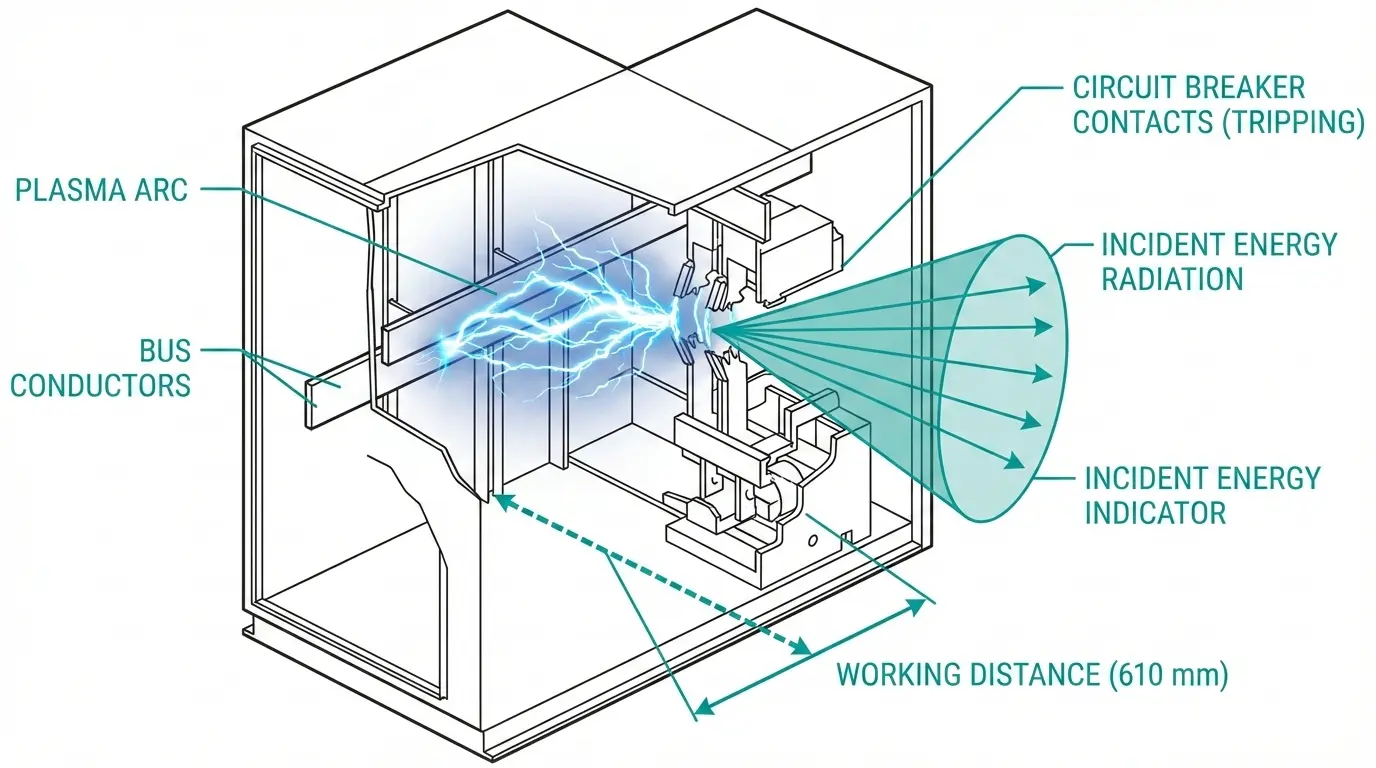
Arc flash events in medium voltage switchgear convert electrical energy into thermal radiation, pressure waves, and molten metal within milliseconds. The difference between a survivable incident and a fatality often comes down to 30–50 ms of breaker clearing time. From our field assessments across 40+ industrial MV installations, we’ve consistently observed that breaker characteristics directly determine how much thermal energy personnel face during an arc flash event.
This guide examines which breaker parameters actually move incident energy numbers, ranks practical mitigation strategies by proven effectiveness, and provides selection criteria for arc flash reduction in MV systems.
Incident energy depends on four primary variables, though one dominates practical mitigation efforts.
According to IEEE 1584-2018 (Guide for Performing Arc Flash Hazard Calculations), incident energy (E) increases approximately linearly with arcing time. A reduction in clearing time from 500 ms to 100 ms can decrease incident energy by roughly 80%, potentially dropping exposure from 40 cal/cm² to 8 cal/cm² at typical working distances of 910 mm for MV equipment.
Arcing Current (Iarc): Not identical to bolted fault current. Arc impedance reduces current flow to 20–85% of the bolted value, depending on electrode gap and system voltage. At 13.8 kV with a 152 mm gap, arcing current typically reaches 60–70% of available fault current.
Arc Duration (t): The time from fault initiation until protective device clearing. This variable has a nearly linear relationship with incident energy—double the duration, nearly double the energy.
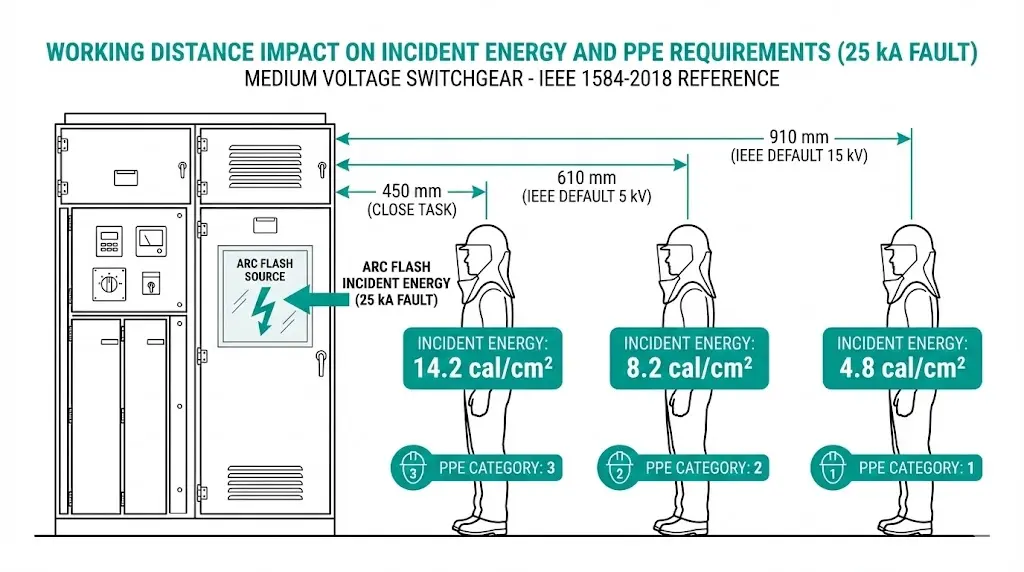
Working Distance (D): Distance from arc source to worker’s face and torso. Energy decreases approximately with the square of distance.
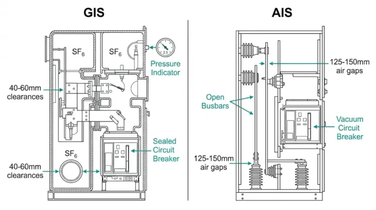
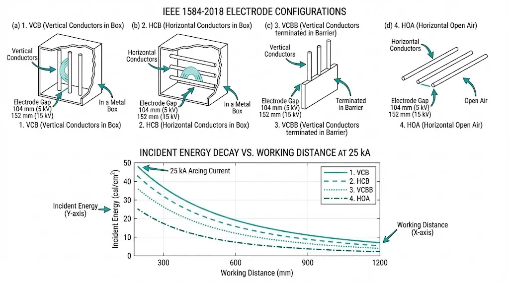
Enclosure Geometry: IEEE 1584-2018 defines specific electrode configurations—VCB (vertical conductors in box), HCB (horizontal conductors in box), VCBB (vertical conductors terminated in barrier). Metal-clad compartments confine plasma and direct thermal energy toward access openings.
Among these variables, arc duration stands alone as directly controllable without replacing switchgear or redesigning system topology. Arcing current depends on utility fault contribution. Working distance has practical minimums for task completion. Enclosure geometry is built into existing equipment. But arc duration responds directly to relay settings, protection schemes, and vacuum circuit breaker operating speed.
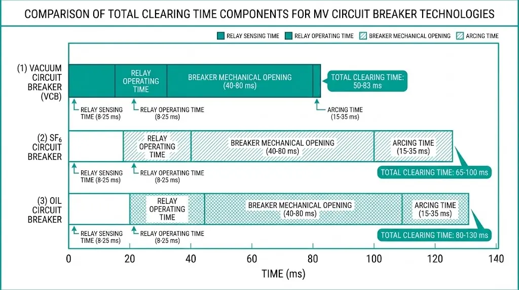
Breaker clearing time comprises distinct intervals, each offering different reduction potential.
Total Clearing Time = Relay Sensing + Relay Operating + Breaker Mechanical Opening + Arcing Time
| Component | Typical MV Range | Reduction Potential |
|---|---|---|
| Relay sensing/operating | 16–50 ms (electromechanical) / 8–25 ms (digital) | High |
| Breaker mechanical opening | 40–80 ms (design-dependent) | Moderate |
| Breaker arcing time | 15–35 ms (current-zero dependent) | Low |
Modern vacuum circuit breakers achieve total clearing times of 50–83 ms (3–5 cycles at 60 Hz). Older oil circuit breakers may require 5–8 cycles. This difference translates directly to incident energy exposure.
A vacuum circuit breaker with 45 ms opening time versus 65 ms opening time reduces arc duration by approximately 30%—translating to roughly 30% lower incident energy when all other variables remain constant.
Specification insight: Request manufacturer test reports showing actual clearing time distribution under full fault current. Nameplate values represent maximums, not typical performance.
[Expert Insight: Clearing Time Verification]
- Factory acceptance tests measure clearing time under controlled conditions; field performance can vary by 5–15 ms due to installation factors
- Request time-current oscillograph records from commissioning for arc flash study input
- Breakers past 70% mechanical life often show 10–20 ms longer operation under fault conditions
- Annual timing tests catch degradation before arc flash calculations become inaccurate
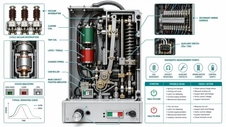
Three breaker parameters govern arc flash severity in MV applications:
Interrupting Time: Total time from relay trip signal to arc extinction. Target ≤50 ms at rated voltage for modern VCBs.
Mechanical Operating Speed: Contact parting time directly affects when arc extinction can begin. High-speed mechanisms achieving contact separation within 25–35 ms after trip initiation substantially reduce total clearing time.
Arc Quenching Capability: Dielectric recovery rate determines restrike probability. Vacuum interrupters achieve dielectric strength recovery exceeding 20 kV/ms, enabling reliable interruption at the first current zero crossing.
| Specification Parameter | Arc Flash Relevance | Target Value |
|---|---|---|
| Opening time | Primary duration component | ≤50 ms at rated voltage |
| Interrupting rating | Must exceed available fault current | ≥25% margin minimum |
| Contact wear indicator | Flags degraded clearing | Specify for maintainability |
| Trip-free mechanism | Prevents holding closed during fault | Mandatory |
| Anti-pumping | Prevents repeated close-open cycling | Mandatory |
Undersized breakers present catastrophic risk. If interrupting rating doesn’t exceed available fault current, the breaker may fail to clear—extending the arc indefinitely. Always verify short-circuit capacity with 25% margin above available fault current.
Vacuum circuit breaker parts condition directly affects clearing performance. Contact erosion increases arcing time. Lubricant breakdown in stored-energy mechanisms—particularly problematic at temperature extremes—extends mechanical operation. Degraded vacuum integrity allows post-arc current continuation.
Several system-level factors affect incident energy beyond breaker selection alone.
IEEE 1584-2018 specifies default working distances:
Reality differs. Racking operations, infrared scanning, and relay testing often occur at closer distances. Each 150 mm reduction increases incident energy by 15–25% depending on enclosure configuration. Document actual task-specific distances in arc flash studies rather than accepting defaults.
Arc-resistant switchgear per IEEE C37.20.7 redirects arc gases away from personnel. It does not reduce incident energy at the arc source—it limits exposure. Standard metal-clad lineups cannot be field-upgraded to arc-resistant ratings.
Solidly grounded systems allow full line-to-ground fault current flow, maximizing ground fault arcing current. Resistance-grounded systems limit ground fault current to 25–400 A, dramatically reducing ground fault arc flash hazard. Phase-to-phase faults remain high-energy events regardless of grounding method.
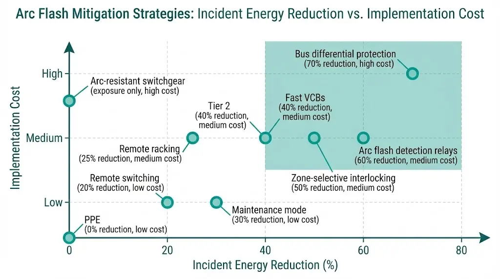
Mitigation approaches fall into three tiers based on incident energy reduction impact.
Field results confirm the impact. Facilities implementing fast-acting vacuum circuit breakers with instantaneous protection settings have achieved incident energy reductions from Category 4 (>40 cal/cm²) to Category 2 (<8 cal/cm²) without modifying system fault current levels.
[Expert Insight: Protection Coordination Pitfalls]
- Maintenance mode settings must be procedurally controlled—forgetting to restore normal settings creates coordination gaps
- ZSI communication failures can cause upstream breakers to trip unnecessarily; verify backup coordination
- Arc flash relays require periodic sensor cleaning in dusty environments to prevent nuisance trips or missed detection
A practical comparison demonstrates the breaker selection impact.
Scenario: 13.8 kV metal-clad switchgear, 25 kA bolted fault current, 610 mm working distance
| Parameter | Breaker A (65 ms clearing) | Breaker B (45 ms clearing) |
|---|---|---|
| Arcing current | 12.4 kA | 12.4 kA |
| Arc duration | 0.065 s | 0.045 s |
| Incident energy | ~8.2 cal/cm² | ~5.7 cal/cm² |
| PPE Category | 3 | 2 |
The 20 ms difference shifts hazard from Category 3 (requiring 40 cal/cm² arc flash suit) to Category 2 (arc-rated clothing sufficient). This affects work planning complexity, PPE procurement costs, contractor access restrictions, and task completion time.
Field measurements confirm that reducing clearing time from 30 cycles to 6 cycles at 30 kA fault current decreases incident energy from approximately 65 cal/cm² to 13 cal/cm²—a reduction factor exceeding 5:1. This underscores why breaker speed characteristics represent the most accessible mitigation lever for existing installations.
For detailed calculation methodology, refer to IEEE 1584-2018 published by the IEEE Standards Association.
Arc flash incident energy reduction begins at breaker specification—fast operating mechanisms, verified clearing times, and consistent interruption under fault conditions. XBRELE manufactures vacuum circuit breakers with documented timing data and the mechanical reliability that protection engineers require for accurate arc flash studies.
For clearing time documentation, coordination study support, or technical consultation on arc flash-optimized MV switchgear, contact our engineering team.
Q1: What single factor has the greatest impact on arc flash incident energy?
Arc duration dominates the calculation—reducing clearing time by 30% typically yields approximately 30% lower incident energy, making breaker speed and protection coordination the most effective mitigation levers.
Q2: How much faster do vacuum circuit breakers clear compared to oil or SF6 breakers?
Modern VCBs achieve 50–83 ms total clearing times (3–5 cycles), while oil breakers typically require 80–130 ms (5–8 cycles), representing a potential 40–50% reduction in arc duration.
Q3: Can arc-resistant switchgear eliminate arc flash hazard entirely?
Arc-resistant construction redirects thermal energy and pressure away from personnel but does not reduce incident energy at the arc source—it manages exposure rather than eliminating the hazard itself.
Q4: How does grounding system type affect arc flash calculations?
Resistance-grounded systems limit ground fault current to 25–400 A, dramatically reducing ground fault arc flash energy, though phase-to-phase faults remain high-energy events regardless of grounding configuration.
Q5: How often should breaker clearing times be verified for arc flash study accuracy?
Timing verification every 5 years or after reaching 50% of rated mechanical operations—whichever occurs first—catches degradation that can add 10–20 ms to actual clearing times.
Q6: Does working distance significantly affect calculated incident energy?
Each 150 mm reduction in working distance can increase incident energy by 15–25% depending on enclosure configuration, making accurate task-specific distance documentation essential for realistic studies.
Q7: What is zone-selective interlocking and how does it reduce arc flash severity?
ZSI enables downstream protective devices to signal upstream breakers to delay, allowing the device nearest the fault to clear without coordination time penalties—reducing total clearing time by 100–300 ms in some protection schemes.