Need Full Specifications?
Download our 2025 Product Catalog for detailed drawings and technical parameters of all switchgear components.
Get CatalogDownload our 2025 Product Catalog for detailed drawings and technical parameters of all switchgear components.
Get CatalogDownload our 2025 Product Catalog for detailed drawings and technical parameters of all switchgear components.
Get Catalog
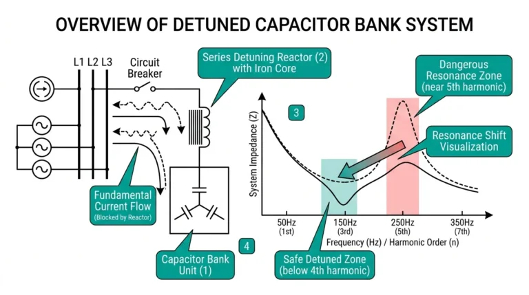
Auxiliary contacts are low-power switching elements mechanically linked to contactors, circuit breakers, and relays that provide position feedback and enable control interlocking. These contacts do not carry load current—they report device state to control systems, SCADA interfaces, and safety circuits that coordinate power system operation.
The designations NO (Normally Open) and NC (Normally Closed) describe contact state when the primary device sits in its de-energized or racked-out position. This distinction causes persistent confusion: “normal” does not mean “normal operating condition.” A normally open contact has no electrical continuity when the breaker is open; it closes when the breaker closes. A normally closed contact works inversely—providing continuity when the device is at rest and breaking its circuit upon device actuation.
In troubleshooting assessments across industrial and utility installations, misunderstanding this fundamental logic accounts for roughly 40% of control circuit failures we encounter. The errors cascade: inverted indications mislead operators, failed interlocks permit unsafe switching sequences, and commissioning teams spend hours tracing faults that originate from a single swapped wire pair.
This guide covers the electrical logic behind auxiliary contact wiring, presents typical schemes for medium-voltage switchgear applications, and catalogs the mistakes that cause real-world failures
Auxiliary contacts change state through direct mechanical coupling to the primary device’s operating mechanism. When a contactor coil energizes—typically requiring 80–110% of rated coil voltage—the magnetic field pulls the armature, actuating both main and auxiliary contacts simultaneously. The contact gap in auxiliary blocks generally measures 2–4 mm, providing adequate dielectric clearance for control circuit voltages up to 250V AC/DC.
Three physical configurations appear across switchgear auxiliary switches:
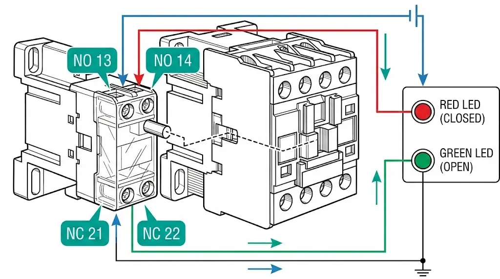
Standard IEC nomenclature uses two-digit terminal numbering: digits 1-2 indicate NC contacts, digits 3-4 indicate NO contacts, and the tens digit identifies contact position in the auxiliary block. Terminal pair 13-14 represents the first NO contact; 21-22 represents the first NC contact.
Field observations reveal that contact bounce during closure lasts approximately 2–5 milliseconds. Without proper filtering, this bounce triggers false signals in sensitive PLC inputs—a troubleshooting issue we address in the common mistakes section below.
The relationship between device position and contact state follows deterministic logic. For a vacuum circuit breaker, the standard designations are:
| Contact Type | Breaker OPEN | Breaker CLOSED |
|---|---|---|
| NO (52a) | No continuity | Continuity |
| NC (52b) | Continuity | No continuity |
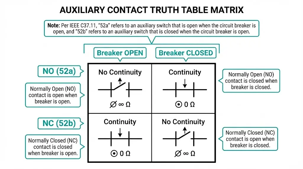
This mechanical dependency means auxiliary contacts reflect actual physical position, not commanded position. If the closing coil energizes but the mechanism jams, auxiliary contacts remain in the “breaker open” configuration—providing genuine position feedback rather than echoing the control signal.
Dual-contact schemes exploit this principle for discrepancy detection. When both 52a and 52b feed separate SCADA digital inputs, the control system expects opposite states. If both read identically—both indicating continuity or both indicating open circuit—the system flags an auxiliary contact fault or mechanism binding condition.
According to IEEE C37.11, auxiliary switches for high-voltage circuit breakers must provide reliable position indication throughout the breaker’s rated mechanical endurance, typically 10,000 operations for MV vacuum circuit breakers.
[Expert Insight: Contact Verification in the Field]
- Always verify contact state with a multimeter during commissioning—resistance should measure <0.1Ω when closed
- Manually operate the mechanism to both positions while observing continuity changes
- Never trust wire labels alone; test the actual contact against known mechanism position
- Document any discrepancy between labeled and measured contact assignments before energization
The most fundamental application routes 52a and 52b contacts to local panel indicators:
+DC ────┬──── 52a ──── RED LED (CLOSED) ──── -DC
        │
        └──── 52b ──── GREEN LED (OPEN) ──── -DC
Breaker open: 52b closed, green LED lit. Breaker closed: 52a closed, red LED lit. Both indications change state simultaneously during normal operation—if only one changes, the discrepancy indicates auxiliary switch failure.
Modern installations assign separate digital inputs for each indication:
| DI Channel | Source Contact | Meaning When DI = 1 |
|---|---|---|
| DI-01 | 52a | Breaker Closed |
| DI-02 | 52b | Breaker Open |
Discrepancy logic in the RTU detects fault conditions:
Configure 10–50 ms debounce filtering to suppress contact bounce during switching transitions.
Preventing parallel source operation requires permissive circuits:
BREAKER B CLOSE CIRCUIT:
+DC → CLOSE PB → 52b(A) → 52b(B) → ANTI-PUMP → CLOSE COIL(B) → -DC
Breaker B closes only if Breaker A is open (52b-A provides continuity) and Breaker B is currently open (52b-B provides continuity for anti-pump logic). This prevents energizing a bus from two unsynchronized sources.
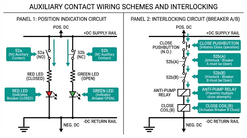
Anti-pumping relays prevent repeated close-trip cycling when a close command persists during a protection trip sequence. The 52b contact breaks the closing coil circuit immediately after successful closure—even if the operator holds the close pushbutton, the breaker cannot re-close until released and the mechanism resets.
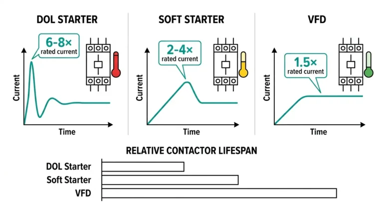
For vacuum contactor applications in motor starting circuits, auxiliary contacts confirm contactor engagement within 200–500 ms of the close command. Failure to receive confirmation triggers a contactor fault alarm in the PLC. Learn more about vacuum contactor integration in motor control systems.
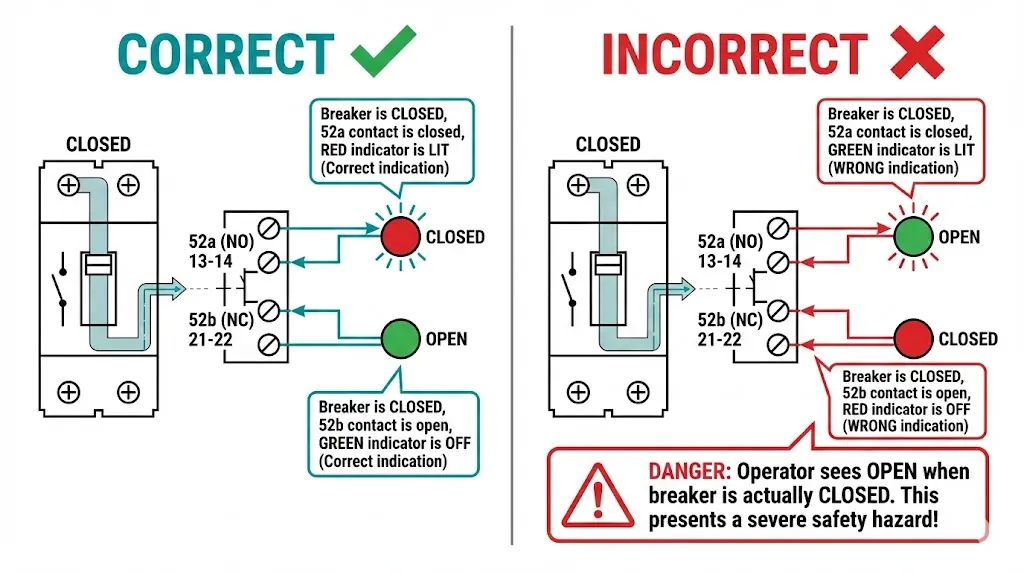
The Error: Connecting 52a to the OPEN indication and 52b to the CLOSED indication.
Consequence: Displays show exactly opposite of reality. Operators see “OPEN” when the breaker is closed. In worst cases, maintenance personnel attempt to rack out a breaker displaying “OPEN” that is actually closed and energized.
Prevention: Verify contact state with a multimeter during commissioning, correlating mechanical position with electrical continuity. Test both positions before connecting to indication circuits.
The Error: Routing multiple loads through auxiliary contacts rated for 5–10 A pilot duty without calculating total current.
Consequence: Contact overheating, accelerated erosion, eventual welding or failure to transfer. Auxiliary contacts rated per IEC 60947-5-1 for utilization category AC-15 handle electromagnetic loads up to 6 A at 230V AC—exceeding this degrades contact life exponentially.
Prevention: Calculate total load current. For loads exceeding ratings, use interposing relays with contacts rated for the actual load.
The Error: Running position indication, interlocking, and SCADA input through a single auxiliary contact.
Consequence: One contact failure simultaneously disables indication, blocks interlocking logic, and blinds the SCADA system. No redundancy remains.
Prevention: Use dedicated contacts for each function. Modern auxiliary switch assemblies provide 8–12 contact elements specifically for functional segregation.
The Error: Confusing Common, NO, and NC terminals on changeover contacts.
Consequence: Using the wrong terminal as Common creates an open circuit in both positions. Swapping NO and NC inverts the logic without obvious indication until a critical operation fails.
Prevention: Consult manufacturer terminal diagrams. IEC and ANSI terminal numbering conventions differ—verify which standard applies to your equipment.
The Error: Connecting auxiliary contacts directly to high-speed PLC digital inputs without debounce filtering.
Consequence: Mechanical bounce produces rapid on-off-on sequences lasting 2–5 ms. Fast-polling inputs interpret this as multiple operations, corrupting cycle counters and triggering false alarms.
Prevention: Configure 10–50 ms debounce in PLC/RTU settings, or install hardware RC debounce circuits for critical inputs.
The Error: Assuming factory wiring is correct and proceeding directly to high-voltage testing.
Consequence: First breaker operation reveals inverted indications or—worse—an interlock that permits unsafe operation due to wiring errors never tested at low voltage.
Prevention: Perform point-to-point continuity verification during site acceptance testing. Manually operate the mechanism while observing all auxiliary contact state changes.
[Expert Insight: Lessons from Commissioning Failures]
- We’ve traced 3-hour troubleshooting sessions back to a single wire landed on terminal 14 instead of terminal 24
- Intermittent faults often stem from loose ferrules on stranded wire—torque terminal screws to manufacturer specification
- When replacing auxiliary blocks from different manufacturers, verify terminal mapping against both old and new documentation
- Photo-document wire positions before disconnecting during maintenance—terminal numbers wear off over years of service
Before energizing any control circuit:
With primary circuit de-energized:
Understanding the operating mechanism helps inform test procedures. Our guide to vacuum circuit breaker working principles covers the mechanical fundamentals that drive auxiliary contact actuation.
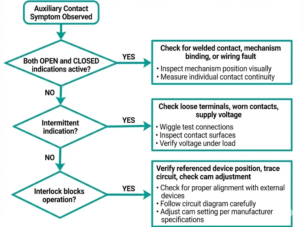
Possible Causes: Welded contact stuck in one position, mechanism binding mid-travel, wiring fault creating false reading
Diagnostic Steps:
Possible Causes: Loose terminal connections, worn contact surfaces, contact bounce without debounce filtering, marginal supply voltage
Diagnostic Steps:
Possible Causes: Referenced device’s auxiliary contact failed open, wiring routes through wrong contact, auxiliary switch cam out of adjustment
Diagnostic Steps:
Contact quantity planning depends on functional requirements:
| Function | Contact Type | Typical Quantity |
|---|---|---|
| Position indication (52a) | NO | 2 |
| Position indication (52b) | NC | 2 |
| Electrical interlocking | NC | 2–4 |
| Anti-pumping | NC | 1 |
| Trip circuit supervision | NO + NC | 2 |
| SCADA interface | Mixed | 2–4 |
| Spare | Mixed | 2–4 |
For full-featured VCB installations, plan for 12–16 total contacts.
Electrical Ratings: Select auxiliary contacts rated for at least 250 VDC when using 110 VDC control systems—this provides adequate margin for voltage variations. Current ratings of 5–10 A suit most pilot duty applications; verify making and breaking capacity for inductive loads.
Mechanical Endurance: Auxiliary switches must match or exceed the primary device’s rated mechanical endurance. For a VCB rated at 10,000 operations, auxiliary switches should meet this figure without contact degradation.
Explore complete auxiliary switch assemblies and switchgear components engineered for MV applications. For vacuum circuit breaker integration requirements, see our VCB manufacturer specifications.
What does “normally open” mean for an auxiliary contact?
Normally open describes the contact state when the associated device is de-energized—the contact has no electrical continuity at rest and closes only when the primary device (breaker, contactor) actuates to its energized or closed position.
How many auxiliary contacts does a typical vacuum circuit breaker require?
Most MV vacuum circuit breaker installations use 8–16 auxiliary contacts, distributed across position indication, interlocking, anti-pumping, trip circuit supervision, SCADA interface, and spare capacity for future requirements.
Can auxiliary contacts directly switch motor loads?
Auxiliary contacts are designed for pilot duty applications with typical ratings of 5–10 A—motor starting currents will cause rapid contact wear, overheating, and eventual welding. Use an appropriately rated contactor controlled by the auxiliary contact instead.
Why does my SCADA display both OPEN and CLOSED indications simultaneously?
Simultaneous contradictory indications typically result from a welded auxiliary contact, mechanism binding in mid-travel position, or a wiring fault that creates a false reading on one input channel. Physical inspection of device position clarifies the actual state.
What debounce time should I configure for auxiliary contact inputs?
Configure 10–50 ms debounce filtering in PLC or RTU digital input settings to suppress mechanical contact bounce during switching transitions—this prevents false operation counts and spurious alarms without significantly delaying legitimate status updates.
How do I verify auxiliary contact condition during maintenance?
Measure contact resistance with a quality multimeter—closed contacts should read below 0.1Ω. Resistance above 1Ω indicates contamination, pitting, or mechanical misalignment requiring contact cleaning or auxiliary switch replacement.
What causes auxiliary contacts to fail prematurely?
Common causes include exceeding current ratings (especially with inductive loads), mechanical wear from high switching frequency, contamination from environmental ingress, and electrical erosion from inadequate arc suppression on DC circuits switching inductive loads.