Need Full Specifications?
Download our 2025 Product Catalog for detailed drawings and technical parameters of all switchgear components.
Get CatalogDownload our 2025 Product Catalog for detailed drawings and technical parameters of all switchgear components.
Get CatalogDownload our 2025 Product Catalog for detailed drawings and technical parameters of all switchgear components.
Get Catalog
Every arc extinguished inside a vacuum interrupter vaporizes microscopic contact material. After thousands of operations, this accumulated erosion determines whether your breaker clears the next fault—or fails when you need it most. Contact wear measurement through systematic resistance testing transforms invisible degradation into actionable maintenance data.
This guide covers practical field methods for assessing contact condition, interpreting resistance values, and making defensible maintenance decisions for vacuum circuit breakers and contactors.
Contact wear measurement is the primary diagnostic method for evaluating vacuum interrupter service condition and predicting remaining operational life. Systematic contact erosion monitoring prevents approximately 85% of unexpected interrupter failures when implemented consistently.
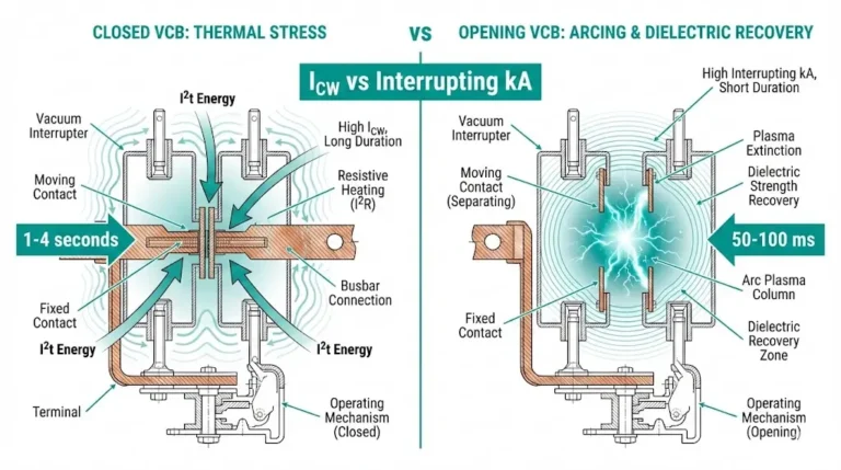
During each switching operation, CuCr (copper-chromium) contacts experience material loss through two mechanisms: arc erosion during fault interruption and mechanical wear during closing operations. Arc erosion dominates in high-fault-current applications, removing 0.1–0.5 mm of contact material per interruption at 25 kA fault levels.
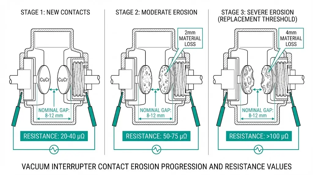
Fresh vacuum interrupter contacts typically maintain a nominal gap of 8–12 mm at full open position. As contacts erode, the effective gap decreases proportionally. When contact wear reaches 3–4 mm total erosion—representing approximately 30–40% of original contact thickness—the interrupter approaches its electrical end-of-life threshold. Beyond this point, dielectric withstand capability degrades below the 42 kV BIL requirement for 12 kV class equipment.
Contact resistance provides an indirect but highly reliable measurement of wear condition. Fresh contacts typically measure below 50 μΩ. Field data from mining and petrochemical installations shows that resistance values increase predictably with contact erosion—typically rising 15–25% as contacts approach replacement threshold.
The relationship between contact erosion depth and resistance follows established patterns documented in IEEE C37.09 testing guidelines [VERIFY STANDARD: confirm current edition clause for contact resistance correlation], enabling maintenance teams to correlate simple resistance readings with actual mechanical wear condition.
[Expert Insight: Field Observations on Wear Patterns]
- Mining applications with frequent motor starting show 3× faster wear progression than utility distribution breakers with equivalent operation counts
- Resistance trending identifies degradation 6–12 months before timing tests reveal mechanical problems
- Phase-to-phase resistance variation exceeding 20% often indicates mechanism misalignment rather than contact wear
- Breakers clearing multiple downstream faults accumulate more wear than operation counters suggest
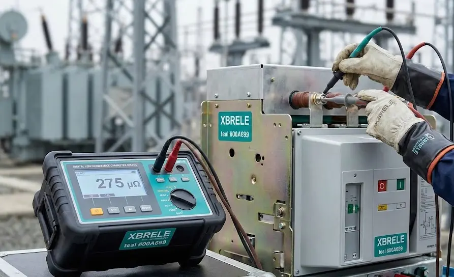
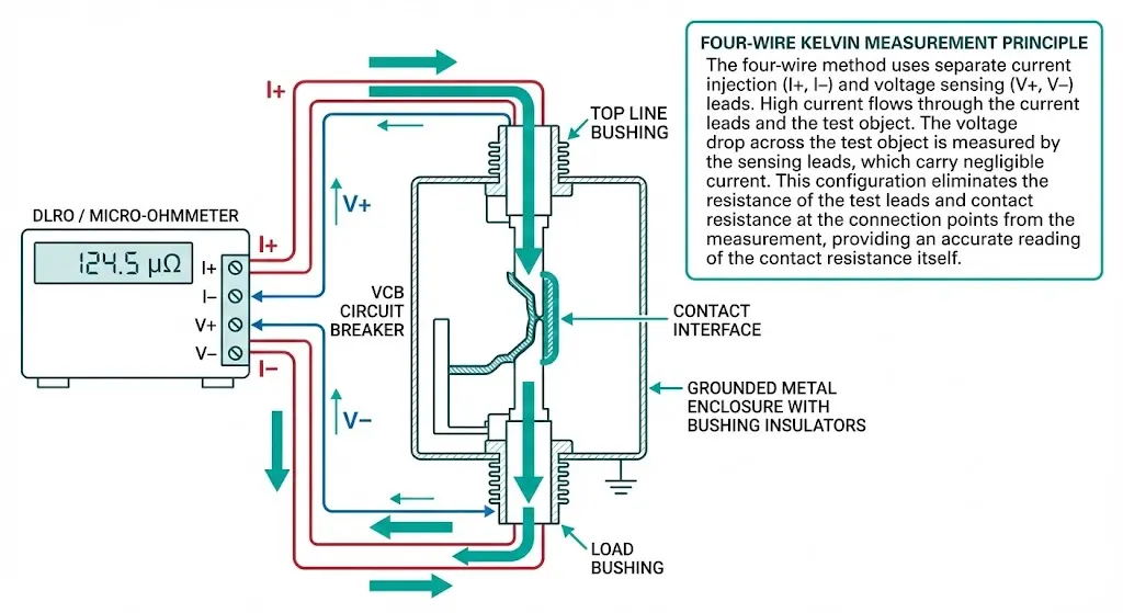
Contact resistance testing exploits a straightforward principle: when test current flows through closed contacts, voltage drop across the contact interface reveals resistance magnitude. The four-wire Kelvin technique eliminates lead resistance errors by using separate current-injection and voltage-sensing circuits.
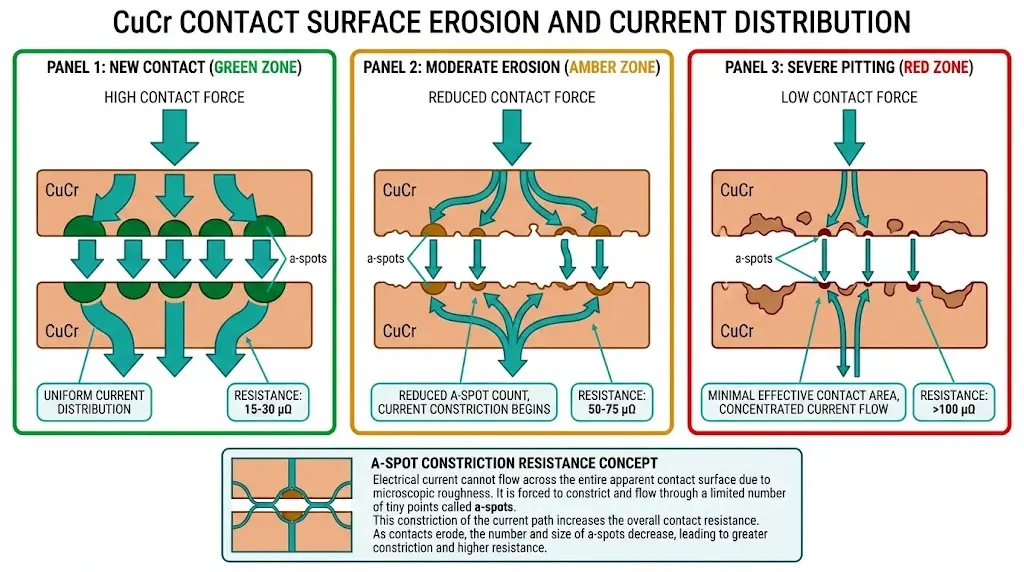
The measured resistance Rcontact comprises three components: bulk resistance of contact material (typically <5 μΩ), constriction resistance at asperity contact points, and film resistance from surface oxides. As wear increases contact gap at the microscopic level, constriction resistance dominates—often representing 60–80% of total measured values in worn contacts.
Testing protocols require DC injection currents of 100–300 A to ensure accurate readings. Lower currents may not penetrate oxide films, producing artificially high readings unrelated to actual contact condition. Most industrial protocols specify 200 A as standard.
Practical Testing Procedure:
Temperature significantly affects measurements. Contact resistance decreases approximately 0.4% per °C rise due to improved contact surface conformity. Testing standards recommend measurements at ambient temperatures between 10–40°C, with corrections applied for deviations from reference conditions.
Fresh CuCr contacts in vacuum contactors and circuit breakers typically exhibit resistance values of 15–50 μΩ depending on design current rating and contact diameter. As wear progresses, micro-pitting and material transfer create irregular surface topology, reducing true metallic contact area and increasing measured resistance.
Contact Resistance Decision Thresholds:
| Condition | Resistance Range | Recommended Action |
|---|---|---|
| New/Baseline | 15–50 μΩ | Document for trending |
| Normal Service | 50–75 μΩ | Continue scheduled monitoring |
| Investigation Required | 75–100 μΩ (or 150% baseline) | Increase test frequency |
| Schedule Replacement | 100–150 μΩ (or 200% baseline) | Plan outage within 6 months |
| Immediate Attention | >150 μΩ (or 300% baseline) | Remove from service |
Phase balance criteria matter as much as absolute values. All phases should measure within ±10% of each other. One phase exceeding 20% deviation from others warrants mechanism investigation before re-energizing.
According to IEC 62271-100, contact resistance values exceeding 1.5× the factory baseline warrant investigation, while values exceeding 2× typically indicate maintenance action. The contact erosion rate depends on cumulative interrupted current, expressed as Σ(I2t), where higher values accelerate wear progression.
Trending resistance values over multiple test intervals provides more diagnostic value than single measurements. A resistance increase exceeding 20% from baseline typically warrants increased monitoring frequency, while values approaching 200% of initial readings indicate imminent replacement need.
Not all switching operations cause equal wear. Understanding acceleration factors helps interpret resistance measurements in context.
Fault current magnitude dominates wear rate. Each interruption of a 25 kA fault current can erode 0.1–0.5 mg of contact material—equivalent to thousands of normal load switching operations. Review protection relay event logs when resistance rises unexpectedly.
Switching frequency accumulates damage. Capacitor bank switching, motor starting applications, and frequent load transfers accelerate wear disproportionately. Mining and steel manufacturing environments sometimes exceed 50 switching operations daily.
Arcing time directly correlates with material loss. Fast protection coordination reduces contact exposure to arc energy. Breakers downstream of current-limiting devices experience less erosion per fault event.
Contact material grade establishes baseline durability. CuCr25 offers superior arc resistance compared to CuCr50 formulations, but material selection occurs at manufacturing—field personnel cannot modify this parameter.
Mechanism wear masquerades as contact degradation. As operating mechanisms age, reduced contact force causes incomplete closure and elevated resistance readings independent of actual contact surface condition. Spring travel exhaustion—typically below 50 N contact force—produces resistance increases unrelated to erosion.
The contact assembly components must function as an integrated system. Worn contacts combined with degraded mechanism springs compound reliability risks beyond what either condition would cause independently.
[Expert Insight: Environmental and Application Variables]
- Coastal installations show resistance increases from salt contamination on external connections—verify connection integrity before condemning interrupters
- High-altitude sites above 1,000 m experience reduced dielectric strength, making contact gap measurements more critical
- Frequent load rejection operations cause asymmetric wear patterns detectable through phase-by-phase resistance comparison
- Ambient temperature swings exceeding 30°C daily accelerate mechanism lubricant degradation, indirectly affecting contact force
Combining contact resistance data with operational history transforms measurements into maintenance intelligence. A vacuum circuit breaker with 8,000 fault operations shows different wear patterns than one with equivalent mechanical operations but minimal fault clearing duty.
Decision Matrix for Maintenance Actions:
| Measurement Result | Operational Context | Action | Timeline |
|---|---|---|---|
| <75 μΩ, stable trend | Normal duty | Continue scheduled monitoring | Annual test |
| 75–100 μΩ or rising 5%/year | Any application | Increase test frequency | Quarterly monitoring |
| 100–150 μΩ | Low fault duty | Schedule replacement | Next planned outage |
| 100–150 μΩ | High fault duty | Prioritize replacement | Within 3 months |
| >150 μΩ or >200% baseline | Any application | Remove from service | Before re-energizing |
| Phase imbalance >20% | Any application | Investigate mechanism | Before re-energizing |
IEEE Std 37.59 provides switching duty classification guidance relevant to wear life estimation [VERIFY STANDARD: confirm current edition for contact wear correlation methodology]. However, experienced maintenance teams recognize that resistance trending rate—not absolute values alone—provides superior wear prediction accuracy.
Documentation creates the foundation for defensible decisions. Record test date, ambient temperature, test current magnitude, instrument calibration status, and all three-phase readings. Without consistent records, trend analysis becomes impossible.
Contact wear measurement ultimately answers one question: when must components be replaced?
Definitive Replacement Triggers:
Replacement options depend on equipment design. Many vacuum circuit breaker configurations permit interrupter-only replacement without full breaker changeout. Complete pole assembly replacement suits designs with integrated interrupter-mechanism packages. Full breaker replacement becomes necessary for sealed designs or when concurrent mechanism wear compromises overall reliability.
Specification Matching Requirements:
Replacement components must match original specifications precisely. Contact material grade (CuCr25 vs. CuCr50) affects arc erosion resistance. Contact travel and gap dimensions must meet original design parameters. Spring force specifications ensure adequate contact pressure—typically 50–80 N minimum for reliable low-resistance interface.
Mixing components from different manufacturers or design generations risks compatibility failures that may not appear during commissioning but surface under fault conditions.
Effective contact wear measurement requires reliable baseline data and technical expertise for interpretation. XBRELE vacuum interrupters ship with factory-verified contact gap specifications and documented initial resistance values, establishing the reference points essential for lifecycle trending.
Our technical team supports maintenance programs across mining switchgear, renewable energy installations, and industrial motor control applications—environments where contact wear rates vary significantly based on switching duty and fault current exposure.
Available Technical Resources:
Contact XBRELE’s engineering team for vacuum interrupter specifications, replacement component quotations, or consultation on establishing condition-based maintenance programs for your switchgear fleet.
What test current magnitude provides accurate contact resistance readings?
Use minimum 100 A DC for medium-voltage contacts, with 200 A preferred for improved signal-to-noise ratio. Lower currents often fail to penetrate surface oxide films, yielding artificially elevated readings that misrepresent actual contact condition.
How does ambient temperature affect contact resistance measurements?
Copper-chromium contact resistance changes approximately 0.4% per degree Celsius deviation from reference temperature. Measurements taken at 40°C require correction factors of roughly 1.08 when comparing to 20°C baseline values for accurate trending.
Can contact resistance testing detect vacuum loss in interrupters?
No—resistance testing evaluates contact surface condition when contacts are closed. Vacuum integrity requires separate assessment through high-voltage withstand testing, X-ray inspection of internal components, or magnetron-based pressure measurement methods.
Why do resistance values sometimes decrease after previous high readings?
Test current flow can break through oxide films that formed since the last measurement, temporarily reducing apparent resistance. This pattern warrants increased monitoring frequency, as underlying contact degradation typically continues progressing.
What causes resistance differences between phases on the same breaker?
Phase imbalance exceeding 15–20% typically indicates mechanism problems—unequal spring force, linkage wear, or misalignment—rather than differential contact erosion. Investigate mechanical systems before attributing variation to contact wear alone.
How many fault operations significantly impact contact wear?
Contact material loss scales with interrupted current magnitude squared. A single 25 kA interruption may cause erosion equivalent to 500–1,000 normal load switching operations, making fault duty history essential context for interpreting resistance trends.
Should baseline measurements be repeated after contact replacement?
Yes—document new baseline resistance values within 30 days of interrupter replacement or major maintenance. Factory specifications provide reference ranges, but actual installed values account for connection quality and mechanism adjustment specific to each installation.