Benötigen Sie die vollständigen Spezifikationen?
Laden Sie unseren Produktkatalog 2025 herunter, um detaillierte Zeichnungen und technische Parameter aller Schaltanlagenkomponenten zu erhalten.
Katalog anfordern
Laden Sie unseren Produktkatalog 2025 herunter, um detaillierte Zeichnungen und technische Parameter aller Schaltanlagenkomponenten zu erhalten.
Katalog anfordern Laden Sie unseren Produktkatalog 2025 herunter, um detaillierte Zeichnungen und technische Parameter aller Schaltanlagenkomponenten zu erhalten.
Katalog anfordern
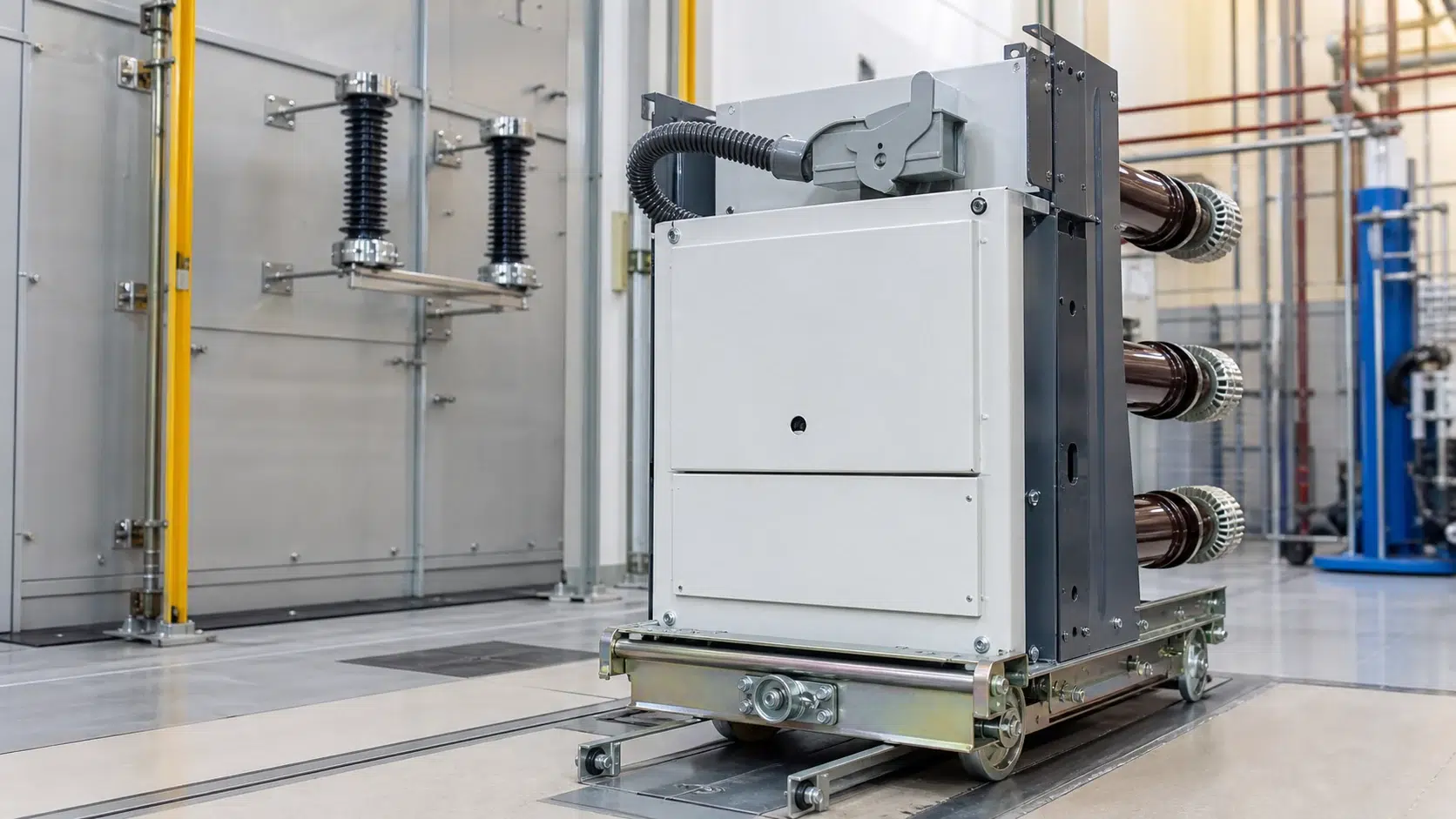
Procuring or manufacturing a 12 kV vacuum circuit breaker (VCB) without a structured compliance map to IEC 62271-100 is a common source of costly project delays, failed witness tests, and rejected factory acceptance documents. The standard is dense, its cross-references are numerous, and the 2021 edition—now consolidated as IEC 62271-100:2021+AMD1:2024—introduced refinements that older internal checklists do not capture. This article translates the standard's principal obligations into a practical, clause-referenced checklist format that procurement engineers, design reviewers, and test witnesses can use throughout a project's lifecycle.
> **Important notice:** IEC 62271-100:2021 is a commercially controlled document. All clause wording, table values, and test sequences cited here are referenced by their published clause numbers. Your project team must work from a purchased, version-controlled copy of IEC 62271-100:2021+AMD1:2024 obtained from the IEC webstore or an authorised national standards body. Do not rely on reconstructed wording from product pages or third-party summaries.
—
IEC 62271-100:2021 applies to alternating-current circuit breakers intended for indoor or outdoor installation, operating at system frequencies of 50 Hz and/or 60 Hz on systems rated above 1 kV. A 12 kV VCB falls squarely within its scope. The standard governs the requirements and test methods for direct making and breaking tests; synthetic test methods are deliberately separated and addressed in IEC 62271-101, which the standard explicitly references for that purpose. For equipment and configuration options, compare the project duty with the XBRELE Vakuum-Leistungsschalter-Programm.
Alongside IEC 62271-100, the parent document IEC 62271-1:2017 provides common specifications for all alternating-current high-voltage switchgear and controlgear for indoor or outdoor installation at service frequencies up to 60 Hz above 1 kV, unless a product-specific standard states otherwise. In practice this means many general requirements—insulation levels, temperature-rise limits, auxiliary circuit specifications, markings, and packaging—are governed by IEC 62271-1 and imported by reference into IEC 62271-100. A compliance checklist that ignores IEC 62271-1 is structurally incomplete.
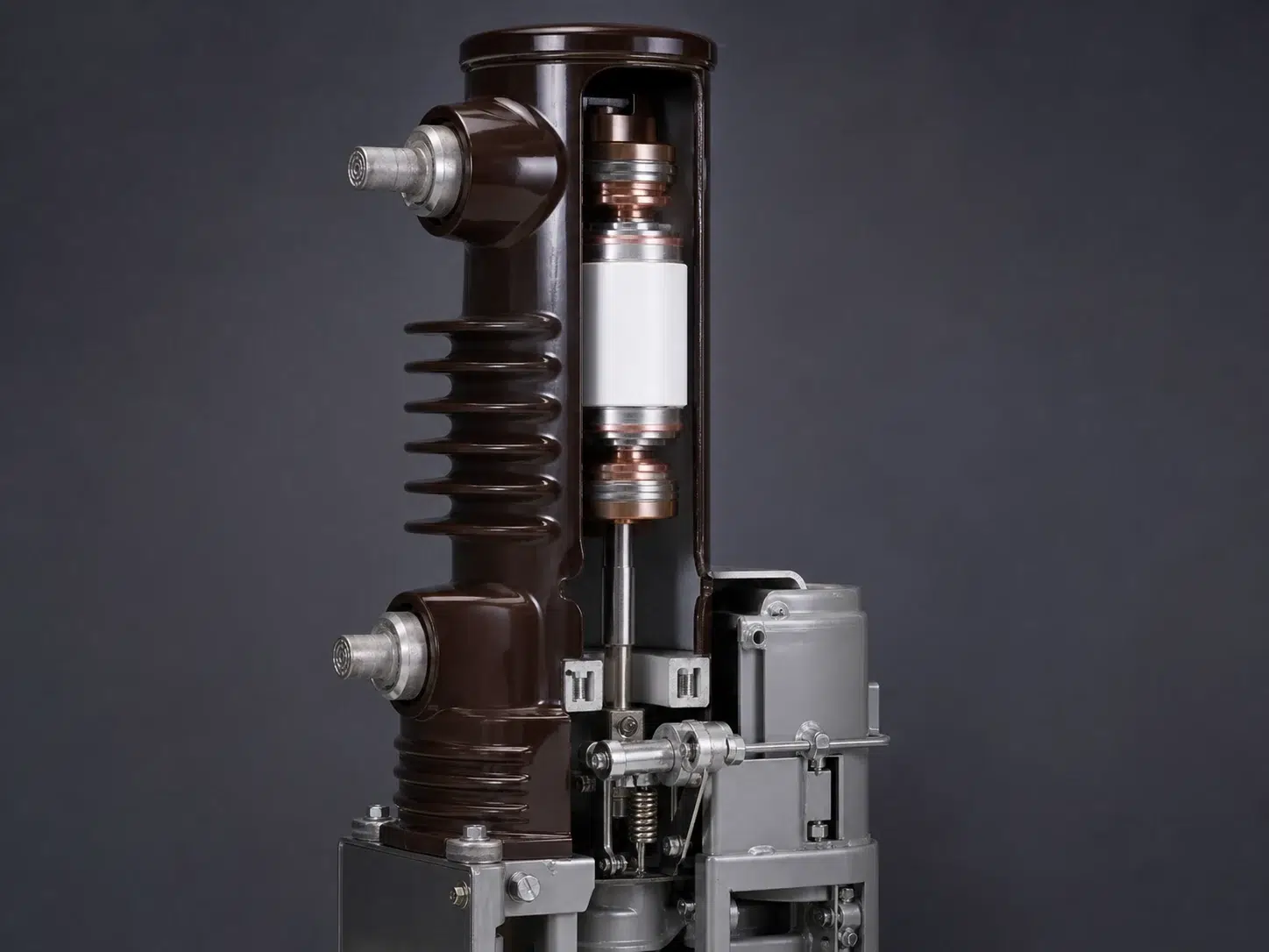
The 12 kV product scope defined in this article corresponds to a rated voltage U_r of 12 kV (maximum system voltage 12 kV per IEC 60038 definitions), typically paired with rated normal currents of 630 A, 1 250 A, or 2 000 A and short-circuit breaking currents of 25 kA or 31.5 kA, though the checklist structure applies at any rating within the 12 kV family.
—
The checklist below is organised by major clause groupings as they appear in IEC 62271-100. Each item states the clause reference, the compliance obligation, the evidence artefact expected, and the responsible party. Use the Status column (Not Started / In Progress / Pass / Fail / N/A) during design reviews and witness testing. For witness planning and records, align the evidence with the VCB acceptance-test checklist.
#### Clause 4 – Normal and Special Service Conditions
| # | Clause | Obligation | Evidence Artefact | Responsible | Status |
|---|---|---|---|---|---|
| 4.01 | 4.1 | Confirm ambient temperature range (−5 °C to +40 °C standard indoor; special conditions documented) | Environmental data sheet, site survey report | Purchaser | Not Started |
| 4.02 | 4.2 | Confirm altitude ≤ 1 000 m or apply correction factors per IEC 62271-1 if site exceeds this | Site altitude certificate | Purchaser | Not Started |
| 4.03 | 4.3 | Confirm humidity class applicable to installation (indoor, condensation control, outdoor) | Switchroom specification | Purchaser | Not Started |
| 4.04 | 4.4 | Document any special service conditions (seismic zone, polluted atmosphere, unusual vibration) and capture manufacturer's written acceptance | Special condition derogation document | Both parties | Not Started |
#### Clause 5 – Ratings
| # | Clause | Obligation | Evidence Artefact | Responsible | Status |
|---|---|---|---|---|---|
| 5.01 | 5.1 | Rated voltage U_r verified as 12 kV on nameplate and in product documentation | Nameplate photograph, data sheet | Hersteller | Not Started |
| 5.02 | 5.2 | Rated insulation level (lightning impulse withstand voltage 75 kV peak; power-frequency withstand voltage 28 kV rms for 12 kV class) confirmed against IEC 62271-1 Table 1 | Type test certificate, dielectric test report | Hersteller | Not Started |
| 5.03 | 5.3 | Rated normal current I_r declared; temperature-rise limits verified by type test | Type test report Clause 6.5 section | Hersteller | Not Started |
| 5.04 | 5.4 | Rated short-circuit breaking current I_sc declared; first-pole-to-clear factor (typically 1.5 for effectively earthed system, 1.3 if confirmed) stated | Rating plate, technical data sheet | Hersteller | Not Started |
| 5.05 | 5.5 | Rated short-circuit making current (peak value = 2.5 × I_sc) stated | Data sheet, test certificate | Hersteller | Not Started |
| 5.06 | 5.6 | Rated operating sequence (O–0.3 s–CO–3 min–CO standard; auto-reclose sequence if specified) declared | Control scheme document, data sheet | Both parties | Not Started |
| 5.07 | 5.7 | Rated short-time withstand current (I_cw) and duration (1 s or 3 s) declared | Data sheet | Hersteller | Not Started |
| 5.08 | 5.8 | Rated cable-charging breaking current and rated line-charging breaking current classes declared | Data sheet, line or cable parameters | Both parties | Not Started |
| 5.09 | 5.9 | Rated out-of-phase breaking current (if applicable) declared or explicitly excluded | Data sheet or derogation letter | Hersteller | Not Started |
| 5.10 | 5.10 | Rated mechanical endurance class (M1 or M2) declared | Data sheet | Hersteller | Not Started |
| 5.11 | 5.11 | Rated electrical endurance class (E1, E2, or E3) declared | Data sheet | Hersteller | Not Started |
| 5.12 | 5.12 | Rated capacitor bank switching classes (C1, C2; restrike class) declared if applicable | Application document, data sheet | Both parties | Not Started |
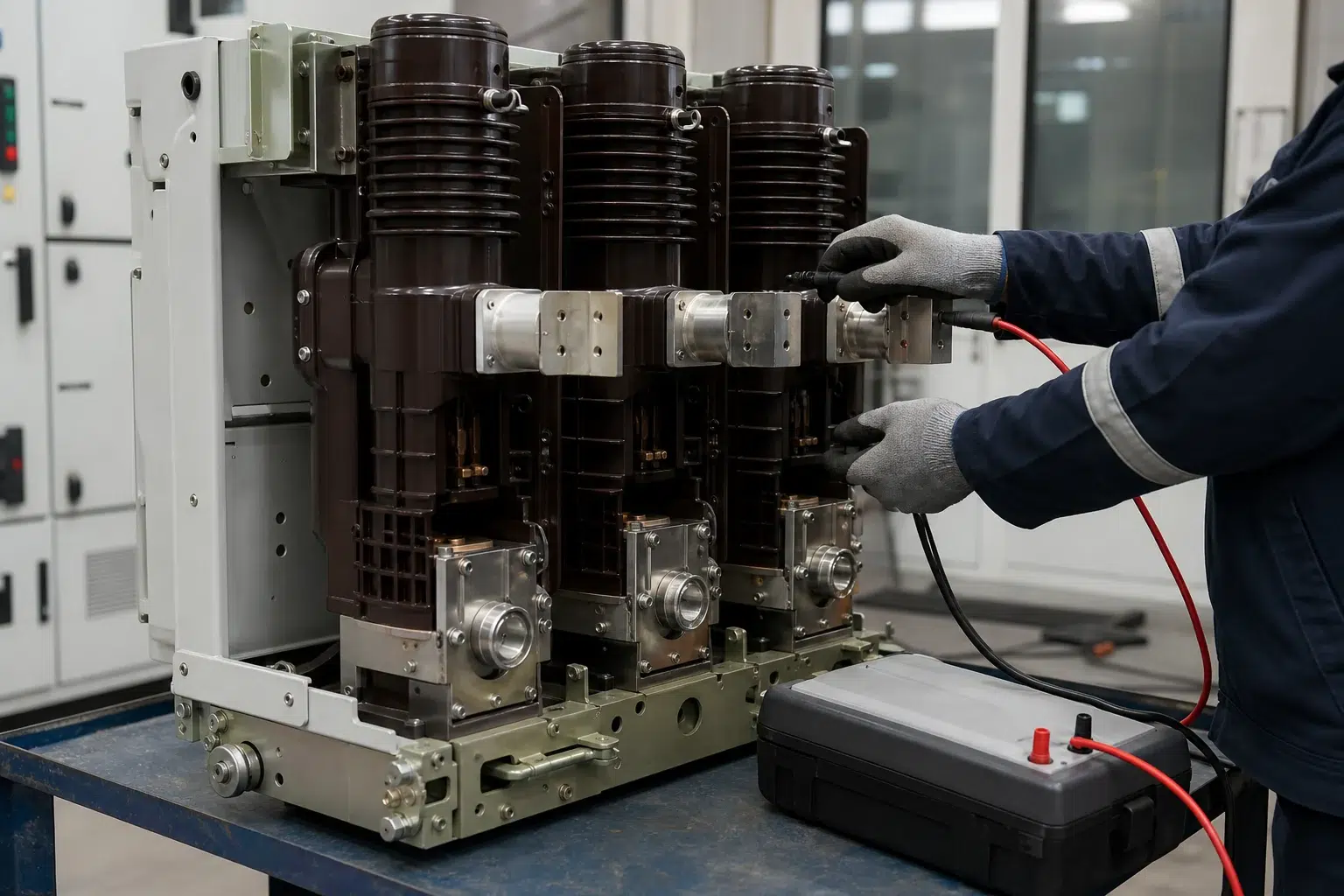
#### Clause 6 – Design and Construction Requirements
| # | Clause | Obligation | Evidence Artefact | Responsible | Status |
|---|---|---|---|---|---|
| 6.01 | 6.1 | Interchangeability requirements met (withdrawable VCBs must be interchangeable within stated range) | Dimensional drawing, interchangeability test record | Hersteller | Not Started |
| 6.02 | 6.2 | Interlocking requirements verified; close-on-test position does not energise primary circuit | Interlocking logic diagram, functional test record | Hersteller | Not Started |
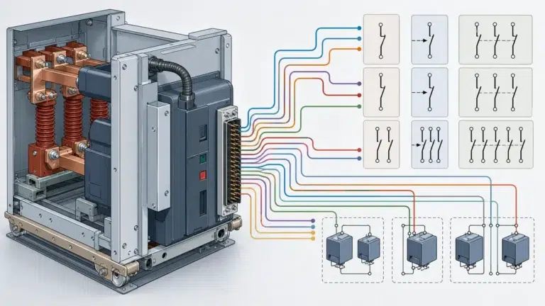
| 6.03 | 6.3 | Auxiliary switches: operation times, contact ratings, and quantity confirmed against protection relay requirements | Auxiliary switch schedule, relay data sheet | Both parties | Not Started |
| 6.04 | 6.4 | Operating mechanism: spring-charged stored-energy mechanism confirmed; manual charging capability present; anti-pumping relay specified | Mechanism data sheet, anti-pump circuit diagram | Hersteller | Not Started |
| 6.05 | 6.5 | Vacuum interrupter: contact gap verified; interrupter pressure/vacuum integrity test at routine test stage | Routine test report, X-ray or hi-pot record | Hersteller | Not Started |
| 6.06 | 6.6 | Creepage distances and clearances in air checked against IEC 62271-1 Clause 6 for the declared pollution degree | Dimensional inspection report | Hersteller | Not Started |
| 6.07 | 6.7 | Degree of protection (IP code) of the enclosure verified by inspection and, if IP5X or above, dust test | IP test report or inspection record | Hersteller | Not Started |
#### Clause 7 – Type Tests (Design-Qualification Tests)
Type tests are performed once on a representative sample to prove that a design meets the standard. The manufacturer's type test certificate must be current, traceable to an accredited laboratory, and cover the specific rating combination being supplied.
| # | Clause | Test | Pass Criterion Summary | Evidence Artefact | Status |
|---|---|---|---|---|---|
| 7.01 | 6.2 (dielectric) | Power-frequency withstand: 28 kV rms, 1 min, across open contacts and to earth | No flashover, no disruptive discharge | Type test report | Not Started |
| 7.02 | 6.2 (dielectric) | Lightning impulse withstand: 75 kV peak, 15 positive + 15 negative | No more than 2 disruptive discharges in 15 shots | Type test report | Not Started |
| 7.03 | 6.5 | Temperature-rise test at I_r (continuous) | Temperature rises within limits per IEC 62271-1 Table 3 | Type test report | Not Started |
| 7.04 | 6.6 | Short-time withstand current test: I_cw for rated duration | No damage; withstand sustained | Type test report | Not Started |
| 7.05 | 6.101 | Short-circuit breaking test (direct method): T10, T30, T60, T100, T100s test duties per Clause 6.101 | Interruption achieved; no dangerous condition | Type test report | Not Started |
| 7.06 | 6.103 | Short-circuit making test | No welding; mechanism intact | Type test report | Not Started |
| 7.07 | 6.104 | Operating sequence tests (mechanical endurance): M1 = 2 000 operations; M2 = 10 000 operations | No failure to operate within stated parameters | Endurance test report | Not Started |
| 7.08 | 6.105 | Electrical endurance: E1 = 100 full-load operations at I_r; E2 = 100; E3 = 200 | Contacts within wear limits; no interrupter failure | Endurance test report | Not Started |
| 7.09 | 6.106 | Cable-charging and line-charging breaking tests (if class declared) | No restrike (C1) or limited restrike (C2) | Type test report | Not Started |
| 7.10 | 6.107 | Capacitor bank switching tests (if applicable) | Class restrike criterion met | Type test report | Not Started |
| 7.11 | 6.108 | Out-of-phase breaking test (if applicable) | Interruption without dangerous overvoltage | Type test report | Not Started |
| 7.12 | 6.2 (post-endurance dielectric) | Dielectric tests repeated after mechanical endurance | Same pass criteria as 7.01–7.02 | Type test report | Not Started |
**Checklist action for Clause 7:** Request the manufacturer's type test report index. Verify that the test laboratory holds an ILAC-MRA accreditation, that the rated values on the certificate exactly match the ordered product rating, and that the certificate issue date plus any supersession by AMD1:2024 are reviewed by your technical authority. Cross-check the duty and nameplate fields against the Leitfaden für die Bemessung von Vakuum-Leistungsschaltern before acceptance.
#### Clause 8 – Routine Tests (Production Tests)
Routine tests are performed on every VCB unit leaving the factory. They are not a substitute for type tests; they verify workmanship and consistent production quality.
| # | Clause | Test | Pass Criterion Summary | Evidence Artefact | Status |
|---|---|---|---|---|---|
| 8.01 | 8.1 | Power-frequency voltage test across open contacts and to earth (reduced level or full level depending on manufacturer's practice) | Kein Überschlag | Routine test report per unit | Not Started |
| 8.02 | 8.2 | Measurement of the resistance of the main circuit (contact resistance, µΩ) at rated normal current per Clause 6.4 | Within manufacturer's declared limit (typically ≤ manufacturer's specification; compare to type test baseline) | Routine test report per unit | Not Started |
| 8.03 | 8.3 | Tightness tests of vacuum interrupters (where applicable, e.g. hi-pot check on interrupter vacuum integrity) | No anomalous partial discharge or dielectric failure indicative of vacuum loss | Routine test report per unit | Not Started |
| 8.04 | 8.4 | Mechanical operating tests: open and close operations at rated, maximum, and minimum control supply voltages | Correct operation at all voltage levels; timing within declared limits | Routine test report per unit | Not Started |
| 8.05 | 8.5 | Design and visual checks: nameplate correctness, wiring, auxiliary circuit labelling, torque marks | Conformance to drawing; no observable defect | Inspection record per unit | Not Started |
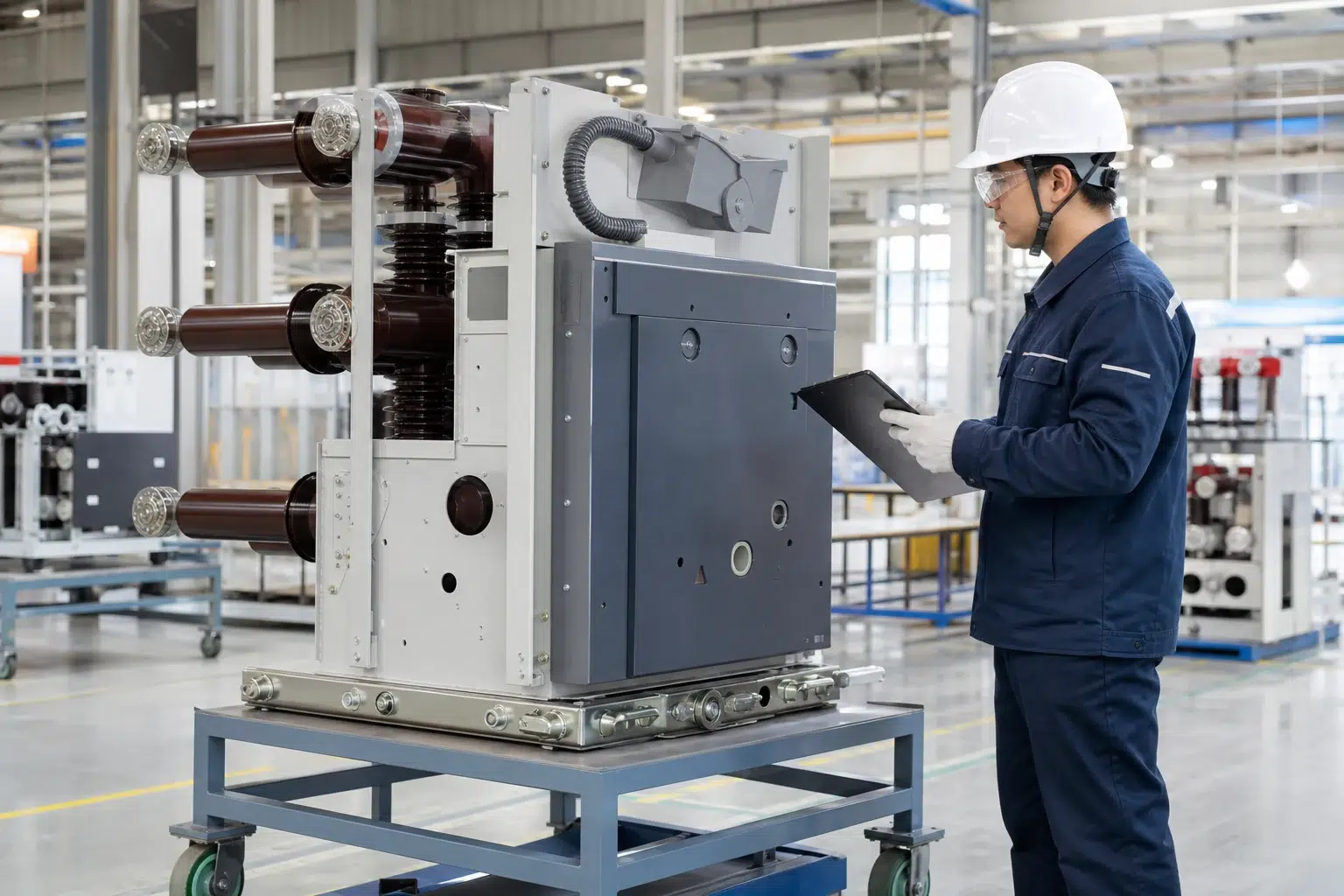
**Checklist action for Clause 8:** Confirm that routine test results are delivered as individual unit reports (not a batch summary), that serial numbers on the reports match the shipping list, and that contact resistance values are trended across the batch to flag any outlier units before dispatch.
—
The checklist is most effective when it is embedded in a formal quality plan (QP) or inspection and test plan (ITP) agreed between purchaser and manufacturer at contract award stage. Assign each checklist item a mandatory witness (W), hold point (H), or review (R) designation:
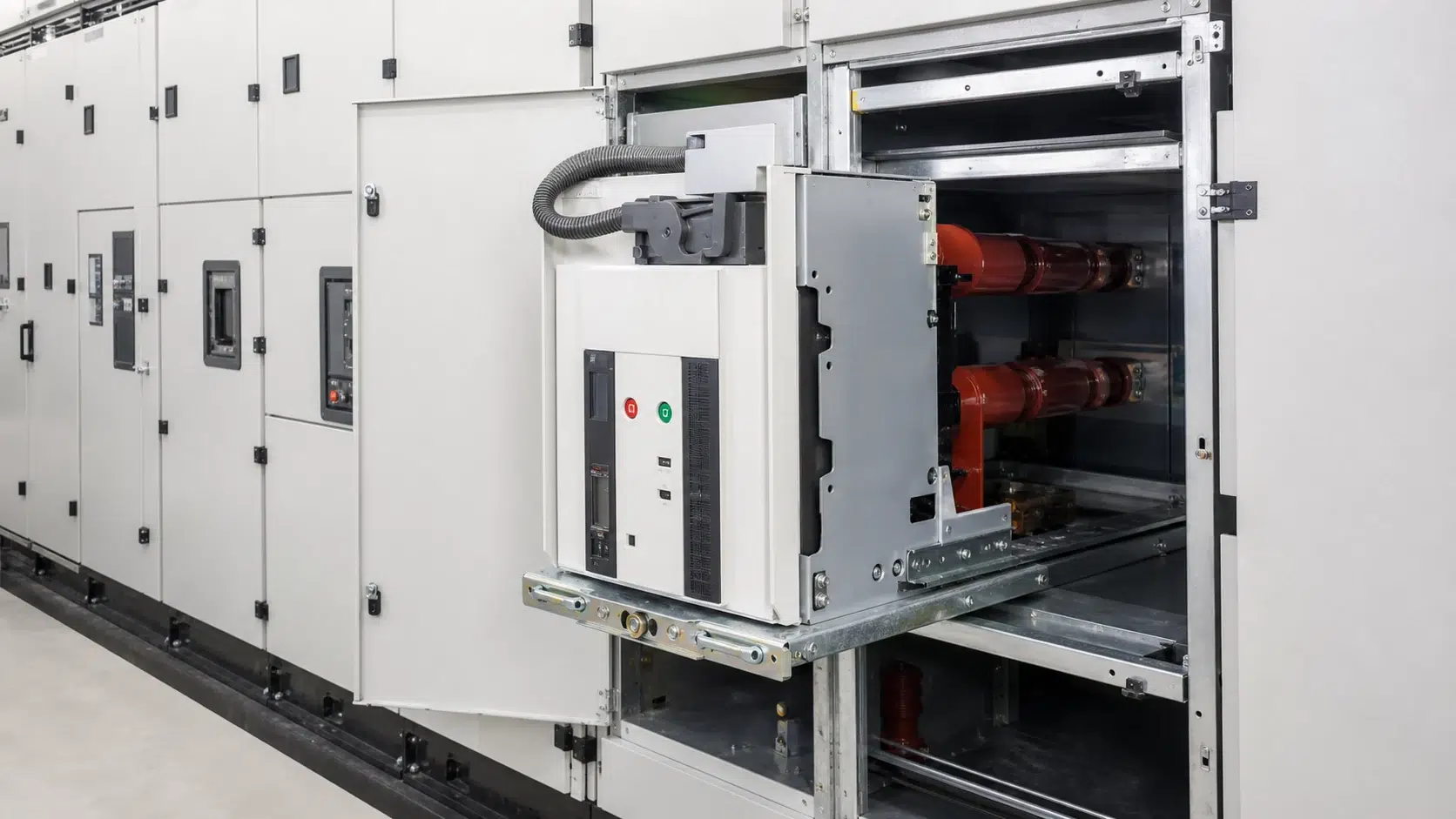
The amendment AMD1:2024 to the 2021 base standard introduced technical changes. Because the IEC webstore lists IEC 62271-100:2021+AMD1:2024 as the consolidated current publication, your project compliance review must use the purchaser's controlled copy of this consolidated edition rather than relying on the 2021 base text alone or reconstructing clause content from public product pages. When issuing the checklist internally, record the document revision of IEC 62271-100 that was current at contract date; do not silently update to a newer edition mid-project without a formal change-impact assessment. Cross-check the requested certificates and reports against the IEC 62271-100 test-evidence guide before RFQ release.
—
Drawing on typical audit experience (not attributable to any specific project under NDA), the following non-conformances appear repeatedly during IEC 62271-100 compliance reviews:
1. **Mismatched type test certificate ratings:** The supplied VCB has a rated short-circuit breaking current of 31.5 kA but the type test certificate on file covers 25 kA. The manufacturer offers a similarity claim that has not been reviewed and accepted by the purchaser's technical authority.
2. **Endurance class ambiguity:** The order specification states "M2 mechanical endurance" but the delivered type test certificate demonstrates only M1. The discrepancy is discovered at FAT, requiring a new type test or a formal design concession.
3. **Contact resistance drift across a batch:** Routine test reports show contact resistance values ranging from 28 µΩ to 94 µΩ across a batch of nominally identical units. No trend analysis was conducted at the factory; no hold point existed to flag the spread.
4. **Dielectric test level confusion:** The manufacturer applied a routine dielectric test at a reduced level without declaring this practice in the contract quality plan. The purchaser expected the full type-test voltage level.
5. **Missing post-endurance dielectric re-test:** The type test report for mechanical endurance shows 2 000 operations but the follow-on dielectric re-test, required to demonstrate insulation integrity after wear, is absent from the report package.
6. **AMD1:2024 changes not reviewed:** The procurement team based their checklist on IEC 62271-100:2021 and did not carry out an impact assessment when AMD1:2024 was published during the project's manufacturing phase.
—
Type tests—referred to in IEC 62271-100 as design-qualification tests—are carried out once on a representative sample of a given design to demonstrate that the design meets every rated characteristic declared under Clause 5. They are normally conducted by the manufacturer at an accredited high-power laboratory, and the resulting certificate is valid for all production units of that design provided no design changes have been made that would invalidate the test results. Routine tests, by contrast, are performed on every individual unit produced. Their purpose is not to requalify the design but to verify that production workmanship has produced a unit consistent with the type-tested design. The Clause 8 routine tests—principally dielectric withstand, main-circuit resistance measurement, vacuum integrity checks, and mechanical operating tests—are therefore an essential complement to type test evidence, not a substitute for it.
Yes. IEC 62271-100:2021 explicitly applies to alternating-current circuit breakers for both indoor and outdoor installation. The principal differences for outdoor units arise in service condition requirements (ambient temperature extremes, UV exposure, pollution level, IP degree of protection) and in the test samples used for certain type tests. An outdoor 12 kV VCB may also need to meet additional seismic performance requirements if site conditions demand it. These additional requirements are typically captured under Clause 4 special service conditions and, where applicable, referenced to IEC 62271-207 for seismic qualification. Confirm with the manufacturer whether the specific product variant has been type tested in the configuration (indoor or outdoor, with or without enclosure) that matches the ordered item.
IEC 62271-1:2017 is the common specification document for all AC high-voltage switchgear and controlgear. It establishes requirements that apply across the entire product family unless a product-specific standard (such as IEC 62271-100 for circuit breakers) overrides them. In a 12 kV VCB compliance review, this means that insulation coordination tables, temperature-rise limits by terminal material, auxiliary and control circuit requirements, terminal markings, and IP protection requirements are found in IEC 62271-1 and are imported by reference into IEC 62271-100. A compliance checklist that addresses only IEC 62271-100 without also verifying IEC 62271-1 obligations is structurally incomplete. Both documents must be available as controlled copies on the project and both must be verified.
IEC 62271-100 permits similarity claims—sometimes called design comparisons or test extrapolation—under defined conditions. The principle is that if a new or modified design is demonstrably similar to, or less onerous than, a design that has already been type tested, the existing type test evidence may be extended to cover the new design. However, similarity claims are not automatic: they require a documented technical justification assessed against the specific rules within the standard for each test category. For short-circuit breaking performance, similarity rules are particularly strict because vacuum interrupter geometry, contact material, and arc-control features can significantly affect breaking capability even when external dimensions appear unchanged. Purchasers should require the manufacturer to provide the full similarity justification document, not merely a certificate that references a similar design, and should have that justification reviewed by a technically competent authority before accepting it.
Because IEC 62271-100:2021+AMD1:2024 is the current consolidated publication, and because amendments can introduce revised test sequences, new requirements, or changed pass criteria relative to the base 2021 edition, the purchaser must carry out a structured impact assessment. This means obtaining the controlled consolidated copy, comparing the clause-by-clause content against any pre-existing checklist that was based on the 2021 edition alone, and identifying every item where AMD1:2024 introduces a change that affects either the manufacturer's type test evidence or the routine test programme. Changes must be captured in a formal project deviation register and resolved before the FAT or, where type test evidence is affected, before contract award finalisation. The IEC webstore identifies IEC 62271-100:2021+AMD1:2024 as the current consolidated version; the project compliance review must be based on the purchaser's controlled copy of this edition rather than on any reconstruction of clause wording from a public-facing product page.
The rated operating sequence defines the succession of open (O) and close-open (CO) operations a circuit breaker must be capable of performing without repair or replacement of components. For a standard VCB, IEC 62271-100 defines the sequence as O–0.3 s–CO–3 min–CO. The first O operation represents a fault-clearing opening; the 0.3-second interval simulates the dead time in an auto-reclose scheme; the CO operation represents reclosing onto a fault and immediately re-opening; the 3-minute interval allows a brief recovery period; and the final CO operation is a second reclose-and-trip cycle. This sequence matters because it directly governs the thermal and mechanical duty imposed on the vacuum interrupter and the stored-energy mechanism. If a project requires a faster auto-reclose cycle or a higher number of fault-interruption operations in quick succession—common in transmission-linked distribution networks—the purchaser must specify this at contract stage and verify that the type test evidence covers the enhanced sequence. Applying a VCB to a duty more severe than its declared operating sequence without type test evidence is a compliance failure.
Contact resistance of the main circuit is measured during routine testing per Clause 8 using a low-resistance ohmmeter (micro-ohmmeter) with a DC test current sufficient to overcome surface film resistance—typically 100 A DC or as specified by the manufacturer. The result, expressed in micro-ohms (µΩ), indicates the combined resistance of the vacuum interrupter contact interface, the conductor joints within the pole assembly, and the main terminal connections. At FAT, the individual unit result should be compared against two benchmarks: the manufacturer's declared maximum limit (stated in the product data sheet and type test report) and the baseline value established during type testing. A unit whose contact resistance significantly exceeds the type-test baseline but remains below the declared maximum should still be flagged for investigation, because elevated resistance indicates increased resistive heating under load current, potential contact surface degradation, or assembly inconsistency. Trending contact resistance across an entire batch—rather than evaluating each unit in isolation—is the most effective way to identify systematic production issues before dispatch.
Electrical endurance classes quantify the number of operations a VCB can perform at or near rated load current without the vacuum interrupter contacts degrading beyond permissible wear limits. E1 requires 100 breaking operations at rated normal current I_r; E2 requires 100 operations but with the test performed at a higher current level representing a more severe duty; E3 requires 200 operations. The class relevant to a specific project depends on the expected frequency of load-switching in service. A VCB used primarily for fault protection in a lightly loaded radial feeder may function adequately with E1 classification, whereas a VCB used for frequent load-switching of a motor or capacitor bank demands E2 or E3 to ensure that contact wear does not prematurely compromise dielectric integrity across the open contacts. Purchasers should verify at specification stage that the electrical endurance class declared on the data sheet is supported by type test evidence and is appropriate for the actual switching duty the VCB will perform in service.
The minimum document package that must be retained for the operational lifetime of the installation—typically 25 to 40 years for medium-voltage switchgear—comprises the type test reports (including any similarity justification documents), the individual unit routine test reports, nameplate photographs, issue-controlled dimensional and assembly drawings, the signed ITP or quality plan with hold and witness point records, a record of the IEC 62271-100 edition used as the compliance reference at contract date, and the manufacturer's maintenance schedule specifying contact wear limits and vacuum interrupter inspection intervals. For projects in regulated industries such as utilities, industrial power, and transport infrastructure, this dossier may also be required to support national regulatory submissions or asset management audits. The document set should be maintained under version control and stored in a manner that ensures accessibility throughout the asset lifetime, including after organisational changes or system migrations that might otherwise result in records being lost.
—
A completed checklist has no value without the underlying evidence. The minimum document package that should accompany a 12 kV VCB delivery under IEC 62271-100 includes:
Organise these documents in a project technical dossier with version control. For projects in regulated industries (utilities, industrial power, transport infrastructure), the dossier may also be required to satisfy additional national regulatory submissions. Ensure the dossier is retained for the lifetime of the switchgear—often 25–40 years—consistent with asset management obligations.
—
Before a 12 kV VCB is put into service, carry out a final compliance verification that bridges the factory acceptance record to the site acceptance test (SAT) context. Confirm that the unit delivered to site matches the serial number on the FAT routine test report, that no damage has occurred during transport (visual inspection of vacuum interrupter access if permitted, mechanism function check, contact resistance re-measurement on site and comparison to FAT baseline), and that protection relay settings align with the rated operating sequence declared on the equipment. Any contact resistance reading on site that deviates significantly from the FAT baseline is a cause for investigation before energisation, not an administrative matter to resolve after the fact.
The investment in a rigorous IEC 62271-100 compliance checklist process is recoverable many times over in avoided failures, reduced insurance and maintenance costs, and the confidence that the breaking performance demonstrated in a type test laboratory will be replicated in service when a fault current actually demands it.