Benötigen Sie die vollständigen Spezifikationen?
Laden Sie unseren Produktkatalog 2025 herunter, um detaillierte Zeichnungen und technische Parameter aller Schaltanlagenkomponenten zu erhalten.
Katalog anfordernLaden Sie unseren Produktkatalog 2025 herunter, um detaillierte Zeichnungen und technische Parameter aller Schaltanlagenkomponenten zu erhalten.
Katalog anfordernLaden Sie unseren Produktkatalog 2025 herunter, um detaillierte Zeichnungen und technische Parameter aller Schaltanlagenkomponenten zu erhalten.
Katalog anfordern

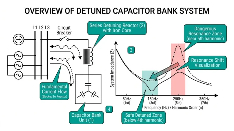
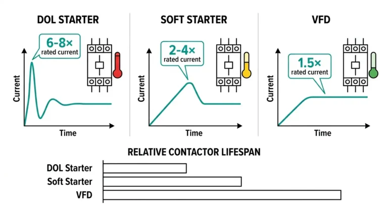
Mittelspannungs-Vakuumschütze arbeiten mit 10.000-100.000 mechanischen Zyklen während ihrer Lebensdauer. Im Gegensatz zu Leistungsschaltern, die Fehlerströme gelegentlich unterbrechen, schalten Schütze Lastströme wiederholt - oft mehrmals täglich bei Motorsteuerung, Kondensatorschaltung und häufigen Start-Stopp-Anwendungen.
Dieser wiederholte Einsatz führt zu Verschleißmustern, die Wartungsteams erkennen müssen, bevor sie zu Ausfällen führen. Kontaktabnutzung durch wiederholte Lichtbögen, mechanische Ermüdung der Betriebsmechanismen und allmählicher Vakuumabbau sind unvermeidlich, aber vorhersehbar. Durch eine strukturierte Wartung wird eine Verschlechterung frühzeitig erkannt, wenn Reparaturen Hunderte statt Tausende kosten und die Ausfallzeit Minuten statt Tage beträgt.
Die meisten Schützausfälle kündigen sich nicht auf dramatische Weise an. Sie kündigen sich schleichend durch messbare Indikatoren an: ein Kontaktwiderstand, der 20% über die Basislinie steigt, ein Zeitablauf, der 5 ms außerhalb der Spezifikation liegt, ein mechanisches Spiel in den Verbindungen. Diese Signale können, wenn sie systematisch verfolgt werden, Ausfälle Wochen oder Monate im Voraus vorhersagen.
Diese Checkliste enthält die spezifischen Tests, Messungen und Abnahmekriterien, die Wartungstechniker benötigen, um den Zustand von Vakuumschützen effizient zu beurteilen. Ob Sie nun industrielle Motorstromkreise verwalten, die Vakuumschütze für zuverlässiges Schalten oder Wartung von Kondensatorbatterien in Umspannwerken gelten diese Verfahren hersteller- und leistungsübergreifend.
Leistungsschalter unterbrechen Fehler - hoher Strom, aber seltene Betätigungen (vielleicht 5-20 während ihrer Lebensdauer). Vakuumschütze schalten Lasten - mäßiger Strom, aber Tausende von Betätigungen pro Jahr.
Dienstleistungsvergleich:
| Parameter | Vakuum-Leistungsschalter | Vakuumschütz |
|---|---|---|
| Typische Operationen/Jahr | 5-20 (Störungsbeseitigung) | 5.000-50.000 (Lastschaltung) |
| Strom unterbrochen | 10-40× Nennwert (Fehler) | 1-8× Nennwert (Einschaltstrom/Last) |
| Lichtbogenenergie pro Vorgang | Sehr hoch | Mäßig |
| Kumulative Lichtbogenenergie | Gering (wenige Operationen) | Hoch (viele Operationen) |
| Wartungsintervall | 2.000–5.000 Operationen | 5.000-20.000 Operationen |
Durch dieses häufige Schalten sammelt sich Lichtbogenenergie an, die die Kontakte erodiert, die Mechanismen belastet und schließlich die Vakuumintegrität beeinträchtigt. Die Wartung verhindert, dass diese schleichenden Ausfälle zu unerwarteten Ausfällen führen.
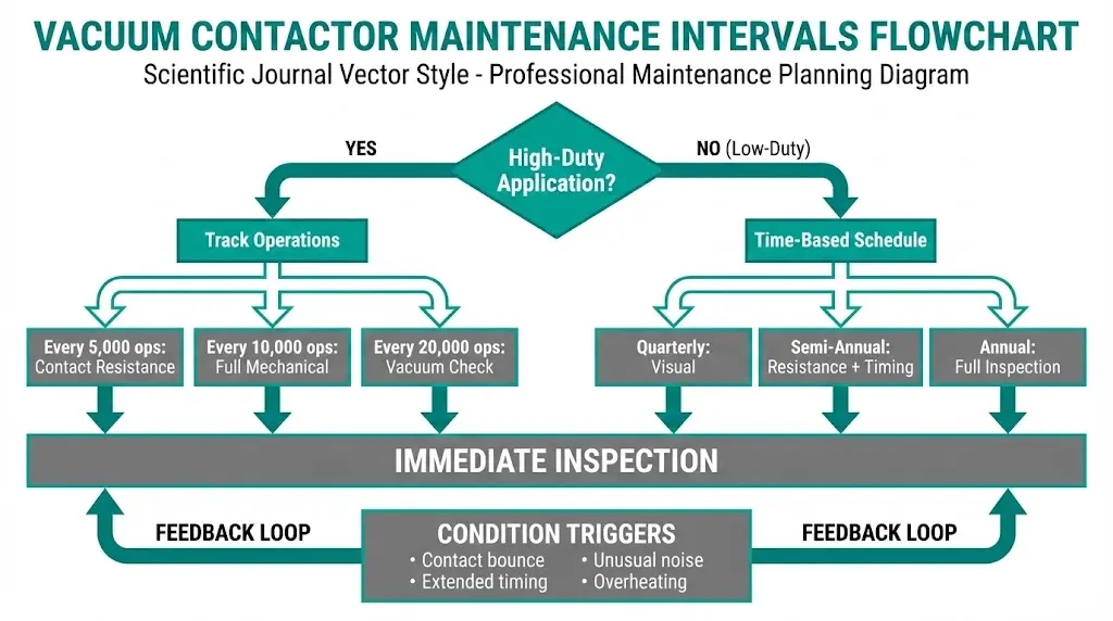
Die Häufigkeit der Wartung hängt von der Betriebsart, den Umgebungsbedingungen und den Empfehlungen des Herstellers ab. Verwenden Sie das konservativere Intervall, wenn die Bedingungen variieren.
Intervall-Leitlinien:
Genauere Genauigkeit als bei zeitbasierten Anwendungen für hohe Beanspruchung:
Wie man Operationen verfolgt:
Führen Sie außerplanmäßige Inspektionen durch, wenn:
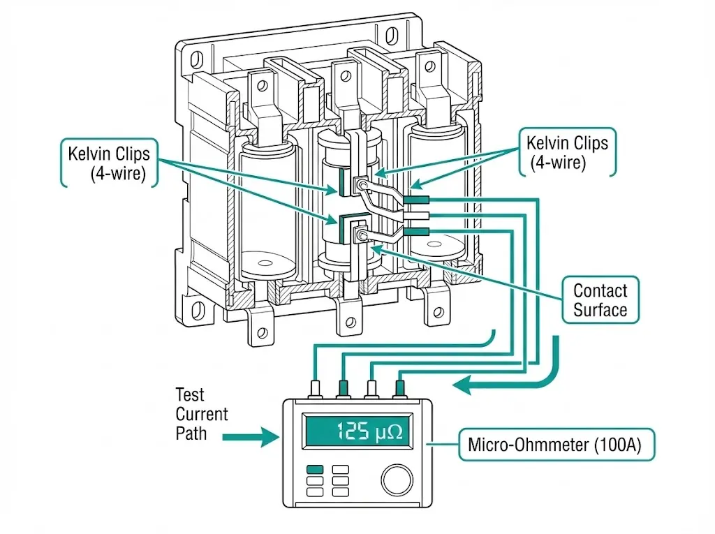
Der Kontaktwiderstand ist ein direkter Indikator für Kontaktabrieb und Oberflächenverschmutzung. Wenn die Kontakte verschleißen, erhöht sich der Widerstand, was die Stromkapazität verringert und die I²R-Erwärmung erhöht.
Absolute Grenzen (typisch für 12-38 kV-Schütze):
Relative Grenzwerte:
Beispielhafte Bewertung:
| Pfahl | Basislinie (neu) | Aktuelle Lektüre | Bewertung |
|---|---|---|---|
| A | 80 μΩ | 120 μΩ | Annehmbar (+50%, normale Abnutzung) |
| B | 85 μΩ | 135 μΩ | Annehmbar (+59%, genau beobachten) |
| C | 82 μΩ | 210 μΩ | Erforderliche Maßnahmen (+156%, nähert sich der Dienstgrenze) |
Pol C zeigt übermäßigen Verschleiß - planen Sie den Austausch der Kontakte beim nächsten Wartungsfenster.
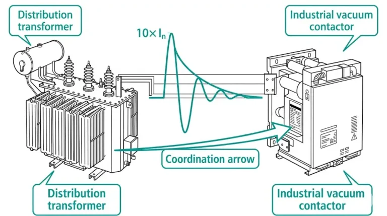
Die Leistung von Vakuumschaltern hängt davon ab, dass der Vakuumdruck unter 10-⁴ Pa (10-⁶ Torr) gehalten wird. Durch den allmählichen Abbau des Vakuums über Jahre hinweg können Gasmoleküle eindringen, was die Durchschlagsfestigkeit und die Unterbrechungsleistung verringert.
Ein vermindertes Vakuum führt nicht zu einem sofortigen Ausfall - die Schütze schalten weiterhin ohmsche Lasten. Die Fähigkeit zur Fehlerunterbrechung nimmt jedoch ab, was bei Einschaltstromstößen oder abnormalen Bedingungen ein Risiko darstellt.
Legen Sie eine Wechselspannung an die offenen Kontakte an und messen Sie den Ableitstrom oder beobachten Sie den Durchschlag.
Ausrüstung:
Verfahren:
Akzeptanz:
Einschränkungen:
Ähnlich wie Methode 1, jedoch mit niedrigerer Spannung, die mit handelsüblichen Megger- oder Isolationsprüfgeräten ermittelt werden kann.
Verfahren:
Vorteile:
Einschränkungen:
Es handelt sich nicht um einen direkten Vakuumtest, aber der Kontaktweg unterhalb der Spezifikation korreliert oft mit dem Vakuumverlust (die Kontakte kleben leicht zusammen, wenn das Vakuum ausfällt und der Innendruck sich ausgleicht).
Grundlegende Reise: Normalerweise 8-12 mm für MV-Schütze
Handlungsebene: <80% des Nennweges kann auf einen Vakuumfehler hinweisen
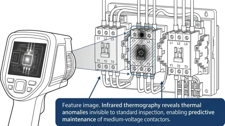
Ein fehlendes Vakuum führt zu einer verstärkten Erwärmung der Kontakte aufgrund einer verminderten Unterbrechungsfähigkeit und interner Lichtbogenbildung.
Verfahren:
Anzeichen für ein Vakuumversagen:
Vorteil: Nicht-invasiv, kann während der Operation durchgeführt werden
Einschränkung: Erfordert Basisdaten und einen geschulten Thermografen
Vakuum-Schaltkammern können nicht vor Ort repariert oder evakuiert werden. Einzige Option: Ersatz.
Ersetzungs-Entscheidungsbaum:
Vakuum-Schaltröhren von qualifizierte Hersteller kosten normalerweise $200-$800, je nach Spannung und Stromstärke. Der Austausch ist einfach - bei den meisten Konstruktionen können die Unterbrecher ausgetauscht werden, ohne dass das gesamte Schütz demontiert werden muss.
Betriebsmechanismen enthalten Lager, Gestänge, Federn und Verriegelungen, die Verschleiß, Korrosion und Fehlausrichtung unterliegen. Mechanische Ausfälle geben oft Warnzeichen, bevor es zu einem katastrophalen Ausfall kommt.
Prüfen Sie auf:
Maßnahme:
Prüfen Sie auf:
Maßnahme:
Prüfen Sie auf:
Maßnahme:
Kontakt Reisemessung:
Ausrüstung: Messuhr oder Wegmessgerät
Verfahren:
Typische Werte: 8-12 mm für 12 kV-Schütze, 10-15 mm für 24 kV
Akzeptanz:
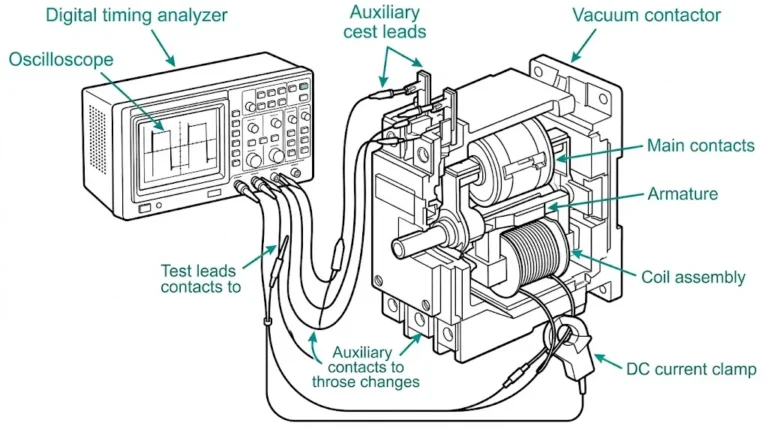
Test der Zeitmessung:
Ausrüstung: Hochgeschwindigkeitsschreiber oder Relaisprüfgerät mit Zeitmessfunktion
Verfahren:
Typische Schließzeit: 50-100 ms
Typische Öffnungszeit: 20-50 ms
Akzeptanz:

Prüfen:
Häufige Ausfälle:
Testverfahren:
Einige Schütze sind mit Lichtbogenschächten oder Barrieren um den Vakuumschalter herum ausgestattet, um zusätzlichen Schutz zu bieten.
Prüfen Sie auf:
Maßnahme:
Betriebsspulen und Steuerstromkreise fallen häufiger aus als Vakuumschaltröhren in gut gewarteten Anlagen.
Zweck: Erkennung von Windungsschlüssen, Isolationsdurchbrüchen oder Spulenschäden
Verfahren:
Akzeptanz:
Verfahren:
Niedriger Isolationswiderstand (<1 MΩ) weist auf ein Eindringen von Feuchtigkeit oder eine Beschädigung der Isolierung hin - trocknen Sie die Spule oder tauschen Sie sie aus.
Schütze, die für AC- oder DC-Steuerspannung (110 V, 125 V, 220 V usw.) ausgelegt sind, reagieren empfindlich auf Unter- und Überspannungen.
Maßnahme:
Unterspannung (<85%):
Überspannung (>110%):
Spannungsabfall prüfen in der Steuerverdrahtung - lange Kabelwege oder unterdimensionierte Leiter verursachen übermäßige Spannungsabfälle.
Rohmessungen sind ohne Kontext nutzlos. Die Entwicklung der Daten im Laufe der Zeit offenbart Verschlechterungsmuster.
Dokumentieren Sie für jedes Wartungsintervall:
Stellen Sie die wichtigsten Parameter im Zeitverlauf dar:
Beispiel einer Trendinterpretation:
Wenn der Kontaktwiderstand im Laufe von 20.000 Betätigungen von 100 μΩ auf 150 μΩ ansteigt, deutet eine lineare Extrapolation darauf hin, dass die 250 μΩ-Grenze bei ~50.000 Betätigungen erreicht wird - planen Sie den Austausch vorher ein.
Muster für eine Checkliste:
VAKUUMSCHÜTZ-WARTUNGSPROTOKOLL

Ausrüstung ID: VC-101
Standort: MCC-3, Schacht 5
Hersteller: XBRELE
Nennspannung: 12 kV
Bemessungsstrom: 400 A
Anwendung: Motorstarter (Lüftermotor)

Datum: _______ Betrieb seit der letzten Inspektion: _______
Umgebungstemp: _______°C

KONTAKTWIDERSTAND (μΩ):
  Phase A: _______ (Basiswert: 85 μΩ)
  Phase B: _______ (Ausgangswert: 82 μΩ)
  Phase C: _______ (Basiswert: 88 μΩ)

ZEITPUNKT:
  Schließzeit: _______ ms (Spezifikation: 60-80 ms)
  Öffnungszeit: _______ ms (Spezifikation: 25-35 ms)

KONTAKTWEG: _______ mm (Spezifikation: 10 ± 1 mm)

SICHTPRÜFUNG:
  [ ] Mechanismus sauber, geschmiert
  [ ] Keine sichtbaren Schäden oder Korrosion
  [ ] Hilfskontakte funktionieren ordnungsgemäß
  [ ] Verriegelungen funktionieren ordnungsgemäß
  [ ] Keine ungewöhnlichen Geräusche oder Vibrationen während des Testbetriebs

ABHILFEMASSNAHMEN ERGRIFFEN:
_____________________________________________

FÄLLICHE NÄCHSTE INSPEKTION: _________ (Datum) oder _________ Betrieb

Inspektor: __________________ Unterschrift: __________
Führen Sie Aufzeichnungen über die gesamte Lebensdauer des Geräts - über Jahre hinweg sichtbare Trends lassen Muster erkennen, die bei einzelnen Inspektionen nicht erkennbar sind.
| Symptom | Mögliche Ursache | Diagnostischer Test | Abhilfe |
|---|---|---|---|
| Lässt sich nicht schließen | Niedrige Steuerspannung, Spulenausfall, mechanische Bindung | Spulenspannung messen, auf Bindung prüfen, Spulenwiderstand prüfen | Spannungsversorgung korrigieren, Mechanismus befreien, Spule ersetzen |
| Lässt sich nicht öffnen | Ausfall der Öffnungsspule, mechanische Verklemmung, festsitzende Kontakte | Manuelle Betätigung (wenn sicher), Test der Öffnungsspule, Prüfung des Kontaktwiderstands | Spule auswechseln, Mechanismus freigeben, wenn Kontakte verschweißt→ Unterbrecher auswechseln |
| Kontakt-Chatter | Unterspannung, verschmutzte Hilfskontakte, mechanische Resonanz | Spulenspannung während des Betriebs prüfen, Hilfskontakte prüfen | Spannung erhöhen, Kontakte reinigen, Dämpfung hinzufügen |
| Übermäßige Erwärmung | Hoher Übergangswiderstand, Überlast, schlechtes Vakuum | Widerstandsmessung, Überprüfung des Laststroms, Vakuumtest | Kontakte reinigen/ersetzen, Last prüfen, Unterbrecher ersetzen |
| Timing außerhalb der Spezifikation | Verschlissenes Gestänge, eingetrocknetes Schmiermittel, Federermüdung | Mechanismus inspizieren, Timing messen, Federzustand prüfen | Nachschmieren, Mechanismus einstellen, verschlissene Teile ersetzen |

Die Wartung von Vakuumschützen birgt elektrische und mechanische Gefahren.
Vor Beginn der Arbeiten:
Während der Prüfung:
Nach der Wartung:
Für die ordnungsgemäße Wartung des gesamten VCB- und Schützsystems siehe Der Vakuum-Leistungsschalter von XBRELE Wartungsanleitung.
Externe Referenz: IEC 62271-106 - IEC 62271-106 Norm für AC-Schütze
Q1: Wie oft sollte ich den Kontaktwiderstand an einem Vakuumschütz messen?
A: Bei Hochleistungsschützen (Motorstart, Kondensatorschaltung) alle 5.000 Schaltungen oder halbjährlich messen, je nachdem, was zuerst eintritt. Für Schütze mit geringer Beanspruchung (<1.000 Schaltspiele/Jahr) ist eine jährliche Messung ausreichend. Legen Sie bei Neuanschaffungen immer eine Basislinie fest und verfolgen Sie Trends.
F2: Was ist der Unterschied zwischen der Kontaktwiderstandsprüfung bei Schützen und bei Leistungsschaltern?
A: Die Technik ist identisch, aber die Akzeptanzkriterien sind unterschiedlich - Schütze akkumulieren bei häufigen Betätigungen mehr Lichtbogenenergie, so dass die Kontakte schneller verschleißen. Die Kontakte von Leistungsschaltern können 10.000 Betätigungen aushalten, bevor sie ausgetauscht werden müssen; Schützkontakte müssen oft nach 30.000-50.000 Betätigungen ausgetauscht werden, obwohl der Strom pro Betätigung geringer ist.
F3: Kann ich ein Standardmultimeter zur Messung des Kontaktwiderstands verwenden?
A: No-Multimeter verwenden Prüfströme im Milli-Ampere-Bereich, die Oberflächenschichten auf Kontakten nicht durchdringen können, was zu falsch hohen Messwerten führt. Verwenden Sie spezielle Mikro-Ohmeter mit 100A+ Prüfstrom, um Oberflächenoxidschichten zu durchdringen und den echten Metall-Metall-Widerstand zu messen.
F4: Wie kann ich feststellen, ob das Vakuum ausgefallen ist, wenn ich keine Hochspannungsprüfgeräte habe?
A: Führen Sie einen 1.000-V-Gleichstrom-Isolationstest über offenen Kontakten durch - ein gutes Vakuum zeigt >100 MΩ. Prüfen Sie auch auf: übermäßige Erwärmung der Kontakte während des Betriebs (Wärmebild), reduzierten Kontaktweg (<80% des Nennwerts) oder ungewöhnlichen Lichtbogen, der durch die Inspektionsfenster sichtbar ist. Jedes dieser Merkmale rechtfertigt den Austausch der Unterbrecher.
F5: Wodurch verlieren Vakuumschaltröhren mit der Zeit an Vakuum?
A: Allmähliche Permeation von Gasmolekülen durch Keramik-Metall-Dichtungen (Helium, Wasserstoff), Mikrorisse durch Temperaturwechsel und interne Ausgasung durch Kontakterosion. Vakuum verschlechtert sich in der Regel im Laufe von 15-25 Jahren, obwohl schwere Betriebs- oder Herstellungsfehler den Ausfall beschleunigen können.
F6: Sollte ich die Kontakte der Vakuumschaltröhren schmieren?
A: Never-Kontakte arbeiten im Vakuum und sollten nicht geschmiert werden. Schmieren Sie nur die Lager, Gestänge und Drehpunkte des Antriebsmechanismus außerhalb des Vakuums. Verwenden Sie das vom Hersteller angegebene Schmiermittel (in der Regel Lithiumfett für -40 bis +125°C).
F7: Wie kann ich voraussagen, wann Kontaktlinsen ersetzt werden müssen?
A: Verfolgen Sie den Widerstandstrend: Wenn er linear von 100 μΩ auf 180 μΩ über 20.000 Einsätze ansteigt, extrapolieren Sie, dass er bei ~50.000 Einsätzen die 250 μΩ-Grenze erreicht - planen Sie vorher einen Austausch. Ein plötzlicher Widerstandssprung (>20% zwischen den Intervallen) rechtfertigt eine sofortige Untersuchung und möglicherweise einen frühzeitigen Austausch.