Benötigen Sie die vollständigen Spezifikationen?
Laden Sie unseren Produktkatalog 2025 herunter, um detaillierte Zeichnungen und technische Parameter aller Schaltanlagenkomponenten zu erhalten.
Katalog anfordernLaden Sie unseren Produktkatalog 2025 herunter, um detaillierte Zeichnungen und technische Parameter aller Schaltanlagenkomponenten zu erhalten.
Katalog anfordernLaden Sie unseren Produktkatalog 2025 herunter, um detaillierte Zeichnungen und technische Parameter aller Schaltanlagenkomponenten zu erhalten.
Katalog anfordern
Selecting the right vacuum contactor requires more than matching a voltage and current rating to a nameplate. A structured procurement checklist maps every purchase decision to a specific operational risk, ensuring that duty category, electrical life, environmental conditions, spare strategy, and supplier capability are all verified before a purchase order is issued. Buyers who skip this process routinely encounter premature contact erosion, mismatched coil voltages, and spare-parts gaps that convert a two-hour repair into a two-week outage.
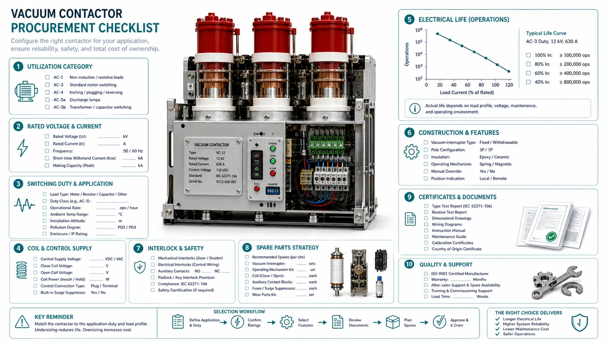
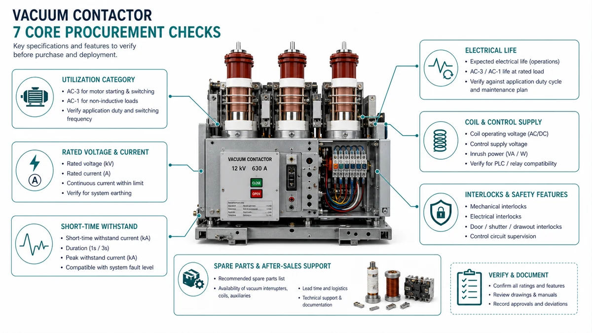
Quick Reference: A complete vacuum contactor procurement checklist must address seven core areas: (1) duty category and load type, (2) rated voltage and insulation level, (3) electrical life in operations at full load current, (4) mechanical life in operations, (5) making and breaking capacity versus actual fault exposure, (6) coil supply compatibility and control circuit voltage, and (7) spare strategy including lead time, interchangeability, and stocking level. Missing any one of these creates a gap between specification and service reality.
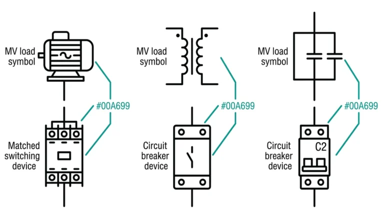
Each checklist item resolves a distinct failure mode. Duty category determines whether the contactor is rated for resistive, inductive, or capacitor-switching service.
| Checklist Item | Decision It Resolves | Risk if Omitted |
|---|---|---|
| Duty category (AC-3, AC-4, AC-6b, etc.) | Load type match | Premature contact erosion or welding |
| System voltage and BIL | Insulation coordination | Dielectric failure at surge events |
| Electrical life (rated operations) | Maintenance interval planning | Unscheduled outage from contact wear |
| Mechanical life (no-load operations) | Actuator and mechanism durability | Mechanism seizure independent of arc erosion |
| Herstellungs- und Ausschaltvermögen | Fault current compatibility | Contactor destruction at first fault event |
| Coil voltage and control power type | Control circuit integration | Failure to close or nuisance dropout |
| Ambient conditions (temp, altitude, humidity) | Derating requirements | Thermal runaway or insulation degradation |
| Lead time and interchangeability | Spare strategy feasibility | Extended downtime due to sourcing gaps |
| Certifications (IEC 62271-106, UL 347) | Regulatory and insurance compliance | Rejection at inspection or claim denial |
Duty category is the single specification that collapses most procurement errors. Two contactors with identical voltage and current ratings can differ by a factor of ten in switching endurance depending on the load type they are designed to handle.
| Pflichtenkategorie | Load Type | Typische Anwendung | Where It Wins | Where It Becomes Risky |
|---|---|---|---|---|
| AC-2 | Slip-ring motors: starting, switching off during run | Crushers, conveyors with wound-rotor drives | Lower inrush severity; moderate contact erosion | Misapplied to squirrel-cage motors with higher inrush |
| AC-3 | Squirrel-cage motors: starting, switching off during run | Pumps, fans, compressors | Standard industrial workhorse; widely stocked | Inadequate for plugging, inching, or jogging duty |
| AC-4 | Squirrel-cage motors: plugging, inching, reversing | Rolling mills, cranes, hoists, test rigs | Rated for high-frequency make-and-break under locked-rotor current | Oversized and more expensive when AC-3 conditions actually apply |
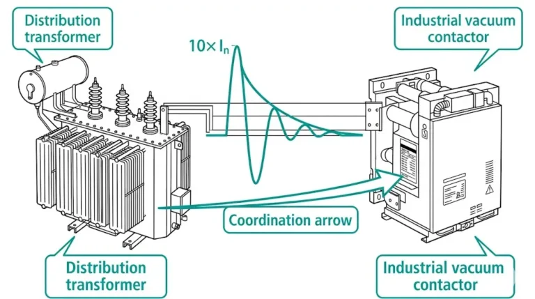
| AC-6a | Transformatoren | Transformer feeders, furnace transformers | Handles magnetizing inrush multipliers up to 8-12x rated current | Wrong choice for motor loads; contact erosion pattern differs |
| AC-6b | Kondensatorbänke | Power factor correction, harmonic filter banks | Rated for capacitive inrush without pre-insertion resistors in some cases | Misapplied to motor loads; arc interruption physics differ |
Question 1: What is the load type? Identify whether the connected load is a motor, transformer, capacitor bank, or resistive load. A slip-ring motor in AC-2 service and a squirrel-cage motor in AC-4 service can share the same rated current but require fundamentally different contact gap geometry and arc-energy management.
Question 2: What is the switching pattern? Count expected operations per hour and per year under worst-case production conditions. A contactor rated AC-3 at 500,000 electrical operations may reach that limit in under three years on a jogging application that actually demands AC-4.
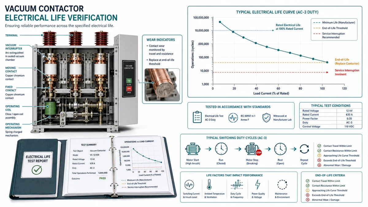
Electrical life is the number of on-load switching operations a contactor can complete before contact erosion degrades performance below an acceptable threshold. That number is only valid at a specific test current, voltage, power factor, and duty category.
| Documentation Provided | Confidence Level | Action if Missing or Incomplete |
|---|---|---|
| Full IEC 62271-106 type test report from accredited lab | High — use rated life directly | Reject or request third-party test before order |
| Manufacturer’s own endurance test report, no third-party witness | Medium — apply 20% life derating | Request witnessed test or accept derating in maintenance plan |
| Datasheet only, no test report available | Low — headline figure unverifiable | Require sample units for incoming inspection; shorten replacement interval |
| Datasheet with conflicting or missing test conditions | Not usable | Do not accept; request corrected documentation |
| Rebuilt or remanufactured unit with no original test data | Not usable for critical duty | Restrict to non-critical standby applications only |
Before scheduling any maintenance activity, work through the diagnosis table below to identify the root cause quickly.
| Symptom | Erster Test | Wahrscheinliche Grundursache | Nächste Aktion |
|---|---|---|---|
| Contactor fails to close on command | Measure coil terminal voltage during trip signal | Coil voltage below pickup threshold (less than 85% rated) | Check control transformer output and wiring resistance |
| Contactor closes but trips immediately | Measure contact resistance across closed main poles | Excessive contact resistance due to erosion or contamination | Measure contact wear; replace vacuum interrupter if at wear limit |
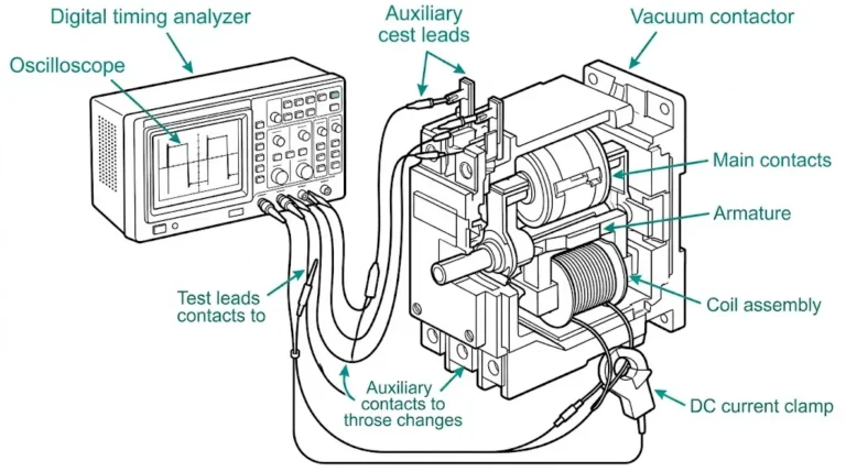
| Nuisance dropout during motor run | Monitor coil voltage under load with oscilloscope | Voltage dip on control supply during motor inrush | Upgrade control transformer VA rating or add hold-in capacitor |
| Audible buzz or chatter on closed contactor | Check AC coil shading ring integrity | Broken or missing shading ring on AC coil face | Replace coil assembly; verify coil voltage is within rated range |
| Interphase flashover on opening | Measure ambient temperature and pollution level | Insulation degradation from conductive contamination or exceeded thermal rating | Clean insulator surfaces; verify enclosure IP rating against site conditions |
| Contact welding on closing | Verify making current against rated making capacity | Inrush exceeds rated making current or wrong duty category applied | Re-evaluate duty category; confirm fault level at installation point |
| Reduced electrical life vs. rated figure | Log operations per hour against nameplate switching rate | Switching frequency above rated duty cycle reference | Install cycle counter; apply thermal derating for elevated duty |
| Instrument | Zweck | Akzeptanz Quelle |
|---|---|---|
| Multimeter (True-RMS) | Coil voltage measurement during operate and dropout | Manufacturer datasheet: pickup <= 85% rated, dropout >= 20% rated |
| Micro-ohm contact resistance tester | Main contact resistance on closed contactor | OEM service manual: typically <= 100 micro-ohm per pole for new unit |
| Insulation resistance tester (1 kV DC) | Pole-to-pole and pole-to-earth insulation | IEC 62271-106: >= 1,000 MOhm at commissioning |
| High-potential (hipot) tester | Vacuum interrupter integrity check | OEM manual or IEC 62271-106 Annex F voltage withstand level |
| Oscilloscope or power quality analyzer | Coil supply voltage profile during motor start | Project specification: no dip below 85% rated Uc during inrush |
| Feeler gauge set | Main contact gap and travel measurement | OEM service manual: contact gap and overtravel tolerance |
| Cycle or operations counter | Total make-break cycle count | OEM manual: compare against rated electrical life at declared duty |
| Timing-Analysator | Messung der Schließ- und Öffnungszeiten | OEM specification: close time typically 40-80 ms; confirm against relay coordination study |
Situation: A 6.6 kV vacuum contactor controlling a 630 kW induced-draft fan was logging nuisance trips approximately 18 months after installation, occurring within the first 30 seconds of each motor start attempt.
Measurements taken: Coil terminal voltage measured at 88 V AC (rated 110 V AC) under steady-state conditions. During motor start, oscilloscope capture showed coil voltage collapsing to 61 V (55% of rated) for approximately 400 ms coinciding with motor inrush. Pickup threshold per OEM datasheet was <= 85% of rated (93.5 V). The 61 V dip caused the contactor to drop out before the motor cleared inrush.
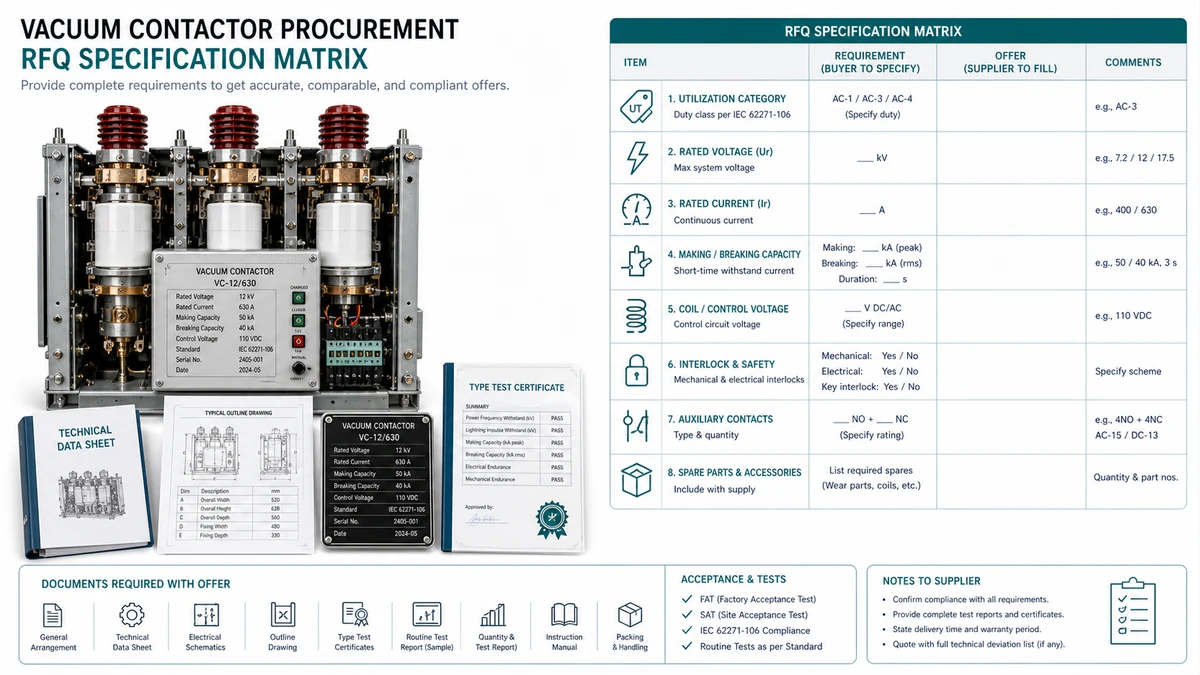
Issuing an RFQ without pinning down the full specification set forces suppliers to quote against assumptions, producing bids that are difficult to compare. Mark each row Confirmed, Pending, or N/A before submission.
| # | Parameter | Required Input | Common Omission Risk |
|---|---|---|---|
| 1 | Utilization Category | AC-3, AC-4, AC-3e, or application-specific per IEC 60947-4-1 | Defaulting to AC-3 on high-inertia or plugging loads |
| 2 | Rated Operational Voltage (Ue) | Nominal voltage plus worst-case sag/swell tolerance | Quoting nominal voltage only; ignoring sag during motor starting |
| 3 | Rated Operational Current (Ie) | Full-load current at the defined Ue and duty category | Using cable ampacity instead of actual motor FLA |
| 4 | Rated Insulation Voltage (Ui) | Must meet or exceed the highest voltage appearing across open contacts including transients | Matching Ui to Ue only; ignoring transient overvoltage class |
| 5 | Rated Impulse Withstand Voltage (Uimp) | Per IEC 60947-1 overvoltage category for the installation | Omitted entirely on low-voltage switchgear specs |
| 6 | Elektrische Lebensdauer | Required cycles at Ie and duty category; specify minimum guaranteed or typical value | Accepting catalogue typical life without a contractual floor |
| 7 | Mechanische Lebensdauer | No-load cycle count for coil and mechanism wear assessment | Assumed equal to electrical life by default |
| 8 | Control Circuit Voltage (Uc) | AC or DC, voltage level, tolerance band | Mismatch between PLC output card voltage and coil rating |
| 9 | Coil Power Consumption | Inrush VA and sealed VA for AC coils; steady-state watts for DC coils | Undersizing control transformer or relay output contacts |
| 10 | Auxiliary Contact Configuration | Quantity of NO and NC contacts, current rating, form factor | Assuming standard 1NO+1NC when project needs 2NO+2NC |
| 11 | Short-Circuit Current Rating | Coordination type (Type 1 or Type 2 per IEC 60947-4-1); prospective fault current | Specifying contactor without upstream SCPD data |
| 12 | Pollution Degree | PD2 (indoor), PD3 (conductive dust or condensation), or PD4 (outdoor or washdown) | Defaulting to PD2 in cement, grain, or chemical environments |
| 13 | Ambient Temperature Range | Maximum operating temperature inside the enclosure | Using room ambient; enclosure internal temperature can be 10-20 deg C higher |
| 14 | Flughöhe Derating | Installation altitude in meters; derating required above 2,000 m per IEC 60947-1 | Ignored on mountain-site or high-plateau projects |
| 15 | Certifications and Standards | IEC 62271-106, UL 508, CSA C22.2, ATEX/IECEx zone classification if applicable | Accepting CE mark as a proxy for UL listing in North American projects |
| 16 | Vacuum Interrupter Traceability | Manufacturer name, part number, and minimum remaining electrical life at delivery | Third-party interrupters substituted without disclosure |
| 17 | Spare Parts Availability Commitment | Minimum years of spare availability post-delivery; coil, interrupter, and contact kit part numbers listed | Supplier discontinues interrupter variant 18 months after delivery |
| 18 | Switching Frequency / Duty Cycle | Operations per hour or per shift for coil thermal derating | Stated as AC-4 duty without quantifying cycles per hour |
Ambient temperature and electrical life: Contact erosion accelerates at elevated temperatures. If your enclosure internal temperature exceeds 55 deg C, request electrical life test data at that temperature rather than the standard 40 deg C reference.
Altitude and insulation voltage: At 3,000 m, derate Ui and Uimp by approximately 20% relative to sea-level ratings, or require a contactor with a higher nominal Uimp.
The gap between a credible supplier and a marginal one rarely shows up in a datasheet — it shows up in what they can and cannot produce when you ask specific questions. Ask every candidate supplier for: type test reports with test dates and laboratory identity, electrical endurance test data showing operations-to-failure curves, dielectric withstand and impulse test certificates, temperature rise test reports at rated current, production batch test records from a recent shipment, and field failure rate data with the basis stated.
| # | Evaluation Criterion | Gewicht | Score (1-5) | Weighted Score | Evidence Required |
|---|---|---|---|---|---|
| 1 | Type test compliance (IEC 62271-106 or equivalent) | 20% | Full test report with lab accreditation | ||
| 2 | Electrical life test data at your duty category | 20% | Endurance curve or tabulated operations count at rated Ie | ||
| 3 | Batch production test records | 10% | Sample test report from recent production lot | ||
| 4 | Environmental qualification (altitude, humidity, corrosion, vibration) | 15% | Derating tables or specific test certificates | ||
| 5 | Field failure rate or MTBF data | 10% | Stated fleet size and operating period | ||
| 6 | Spare parts availability and lead time commitment | 10% | Written lead time for vacuum interrupters and coils | ||
| 7 | Technical support capability | 5% | Named contact, response time SLA | ||
| 8 | Factory audit or third-party quality certification | 5% | ISO 9001 scope, recent audit date | ||
| 9 | Traceability and counterfeit-risk controls | 5% | Serial number traceability, authorized distributor chain |
Scoring anchors: 5 = full documentation provided, independently verified, no gaps; 4 = documentation provided with minor gaps closable within 5 business days; 3 = partial documentation with a supplier-committed timeline; 2 = missing key criterion with vague supplier response; 1 = no documentation available or supplier declines to provide it.
Minimum threshold: A weighted total below 3.0 should disqualify the supplier regardless of price. A score of 3.0-3.5 warrants conditional approval with documented risk acceptance. Above 4.0 is preferred for critical or high-cycling applications.
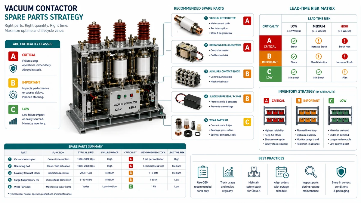
A spare-parts strategy that works for a cement plant running contactors at 80% of rated duty will fail a food-processing facility operating the same device at 30% duty with quarterly planned shutdowns. The framework below ties inventory decisions to three variables: criticality of the driven load, actual switching frequency, and your site’s acceptable mean time to restore (MTTR).
| Klasse | Definition | Inventory Target | Reorder Trigger |
|---|---|---|---|
| A – Critical | Load loss causes process shutdown, safety interlock, or revenue loss >4 hours | Minimum 1 complete spare on-site; vacuum bottle held separately | Stock falls below 1 unit |
| B – Important | Load loss degrades output but backup or bypass exists | 1 spare per 4-6 installed units; consumable parts kitted | Stock falls below 50% of par level |
| C – Non-critical | Load loss tolerable for planned maintenance window (>72 hours) | Shared pool or supplier-held consignment acceptable | Annual review cycle |
| Schalthandlung | Typical Cycle Rate | Vacuum Bottle Review Point | Coil and Spring Review Point |
|---|---|---|---|
| Light (<= 30% of rated duty) | Less than 10,000 cycles/year | At 50% of rated electrical life or 5 years, whichever comes first | 10 years or major overhaul |
| Moderate (30-60%) | 10,000-50,000 cycles/year | At 40% of rated life or 3 years | 6 years or major overhaul |
| Heavy (>60%) | More than 50,000 cycles/year | At 25% of rated life or annual inspection | 3 years or condition-based |
A matched quotation requires structured technical data, not just a voltage and current rating. Submitting complete technical data at the inquiry stage compresses the evaluation cycle and reduces the risk of a mismatched selection reaching site.
System and Load Parameters
– Nominal system voltage (kV) and insulation level (BIL, kV)
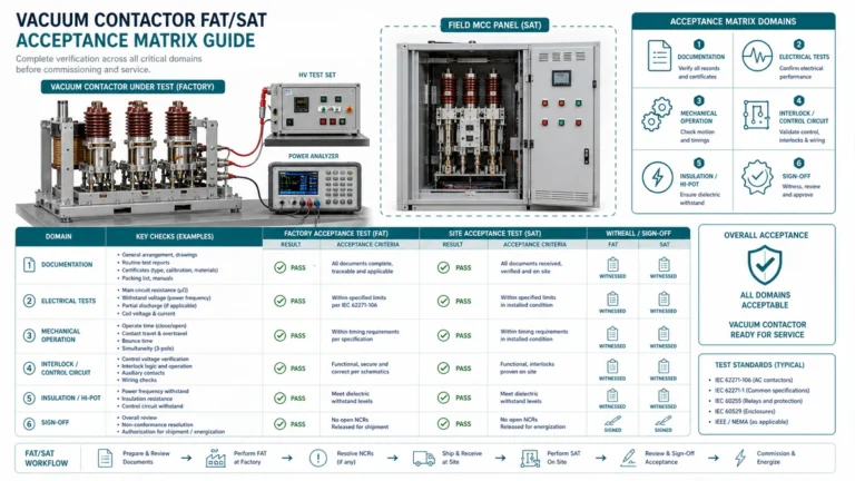
Verwenden Sie diese XBRELE-Referenzen, um die Feldentscheidung mit dem richtigen Produkt-, Test- und Beschaffungsablauf zu verbinden: XBRELE Produktseite, XBRELE Vakuum-Leistungsschalter-Programm, VCB-Rating-Leitfaden, VCB FAT/SAT Annahme-Checkliste, XBRELE-Vakuumschütz-Baureihe.
Für externen Methodenkontext vergleichen Sie die Site-Prozedur mit der öffentlichen IEEE C37.09 Normen Seite und wenden Sie dann das genaue OEM-Handbuch und die Projektspezifikation für die gelieferte Ausrüstung an.
Beispiel aus der Praxis: Bei einer Wartungsinspektion wurde bei einer Phase eine Abweichung von der Inbetriebnahme-Basislinie gemessen, während die beiden anderen Phasen stabil blieben. Das Team wiederholte die Messung mit verifizierten Leitungen, überprüfte das Timing und den Kontaktweg und nutzte die gemessene Abweichung, um ein Kontaktdruckproblem von einem allgemeinen Oberflächenreinigungsproblem zu unterscheiden.
AC-3 covers squirrel-cage motors where the contactor makes against locked-rotor current but breaks only running current. AC-4 adds plugging, inching, jogging, and reversing duty, where the contactor must both make and break at locked-rotor current.