¿Necesita las especificaciones completas?
Descargue nuestro Catálogo de productos 2025 para obtener planos detallados y parámetros técnicos de todos los componentes de los equipos de conmutación.
Obtener catálogo
Descargue nuestro Catálogo de productos 2025 para obtener planos detallados y parámetros técnicos de todos los componentes de los equipos de conmutación.
Obtener catálogo Descargue nuestro Catálogo de productos 2025 para obtener planos detallados y parámetros técnicos de todos los componentes de los equipos de conmutación.
Obtener catálogo

Size a transformer for motorstarting by checking startingcurrent, sourceimpedance, busandmotorterminalvoltage, accelerationtime and otherloads beyond runningkVA.
A transformer chosen on running kVA answers one question: can it carry the continuous load without exceeding its temperature rise? It does not by itself demonstrate performance during a motor-starting interval. That event is governed by different numbers — locked-rotor current, the impedance of everything between the motor and the source, and how much torque the motor can still develop once the voltage has sagged. For a project with a demanding start, the voltage and acceleration check can determine the transformer requirement.
The two duties fail for different reasons, so they need different data and different acceptance criteria.
The continuous duty is a thermal question. The transformer must deliver the required running kVA while dissipating its own losses within its temperature-rise limits at the actual ambient, altitude and enclosure. That is where loss data at reference temperatures, cooling class and ventilation guidance matter. It is a steady-state calculation with steady-state inputs.
The starting duty is a voltage and time question. Its duration and current depend on the motor, starter, voltage and load. A direct-on-line start can draw several times full-load current and it flows through the whole upstream path at once. The consequence is a voltage depression that is felt by the starting motor, by every other load on the bus, and sometimes by the utility’s own network at the point of common coupling.
These are not interchangeable criteria. The voltage-drop limits that installation guides publish for steady-load distribution design — the percentages used to size feeders and check running conditions — do not apply to motor starting. The Schneider Electric Electrical Installation Guide states this directly, and adds the practical warning: too low a starting voltage can leave the motor stalled or accelerating so slowly that it draws a high current for a long time. That warning is the whole problem in one sentence. Slow acceleration is not a milder outcome than stalling; it is a longer thermal event for the motor and for the transformer feeding it.
So where does the starting acceptance limit come from? From the project. From the utility’s flicker or dip rule at the point of supply, from the process’s tolerance for a disturbed bus, and from the ride-through capability of the other loads connected to it. There is no universal number to borrow.
The physical picture is a series path. Source impedance — the utility network’s short-circuit level and X/R, or a generator’s subtransient reactance — feeds the transformer, which feeds the feeder, which feeds the motor. Refer impedances and currents to a common voltage and power base before combining their contributions. Physical primary and secondary amperes differ across the transformer, and upstream elements also carry other connected loads. Each contribution depends on the relevant current and complex impedance. The motor terminal voltage is whatever is left after all three have taken their share. A transformer that looks generously sized against running load can still be the element that takes too much.
Before any calculation, gather the data the event actually depends on. Missing one of these is what turns a study into a guess.
| Group | Input | Why the event needs it |
|---|---|---|
| Motor | Rated voltage, full-load current, locked-rotor current or locked-rotor kVA, starting power factor | Sets the current magnitude drawn during the start and its phase angle |
| Motor | Manufacturer’s current and torque versus speed curves | Real machines do not hold locked-rotor current constant to full speed |
| Starting method | DOL, star-delta, autotransformer, soft starter with current limit and ramp, VFD | Determines the current the motor is allowed to draw and the voltage it receives |
| Load | Load torque versus speed, total inertia (motor plus driven machine), breakaway torque | Decides whether the reduced torque is enough to accelerate |
| Deber | Required acceleration time, permissible starts per hour, motor thermal withstand (hot and cold) | Converts the voltage dip into a thermal judgement |
| Fuente | Utility short-circuit level and X/R at the supply point, or generator subtransient reactance and excitation behaviour | The first impedance in the path, and often the largest |
| Transformador | Rated kVA, percentage impedance, X/R ratio, tap position, cooling class, present loading and winding temperature | The element under consideration, but not the only one |
| Distribución | Cable and busway resistance and reactance per unit length, route length, number of parallel runs | The last impedance before the motor terminals, and the one most often underestimated |
| System state | Other loads on the bus at the moment of start, and their sensitivity | A start during a plant shutdown is not the same event as a start at full production |

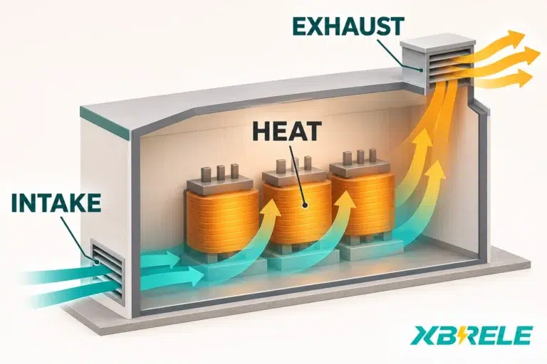
The distinction that figure 1 draws is easy to state and easy to forget: there are two current levels, and they demand two different sets of numbers. The high narrow peak needs impedance and torque data. The long low plateau needs loss and temperature-rise data. Sizing a transformer on the second alone leaves the first unexamined.
An important arithmetic error in transformer starting checks is to multiply the percentage impedance by the running load. A 6% impedance gives a series impedance-drop magnitude of 3% at half rated current on that base. This is not automatically a 3% reduction in terminal-voltage magnitude: the R/X split, current angle, upstream voltage and other circuit elements matter.
The clean way to handle this is per-unit, on one declared base.
Choose a base power, normally the transformer rating, and a base voltage at the point you are calculating. Then:
Now express the starting demand on the same base. If the motor draws 500 kVA of locked-rotor demand at nominal voltage and the base is 1000 kVA, the starting current is 0.5 pu. The transformer at 6% impedance is 0.06 pu. A first-order estimate of the drop across the transformer is the product of the two current and impedance quantities, resolved by the starting power factor:
ΔU ≈ I_start,pu × (R_pu cos φ + X_pu sin φ)
where φ is the starting current phase angle and cos φ is the starting power factor, rather than the running power factor.
Worked illustration. Take a 1000 kVA base, a 500 kVA starting demand at nominal voltage, and a transformer of 6% impedance. The starting current is 0.5 pu, the impedance is 0.06 pu, and the magnitude of the impedance drop is 0.5 × 0.06 = 0.03 pu, or about 3% of nominal voltage. The voltage-magnitude projection requires the actual R/X split and starting power factor; do not assume it equals the gross 3% magnitude.
Read that 3% for exactly what it is and nothing more. It is the drop across the transformer’s own impedance, computed under four assumptions: an infinitely stiff source, no other load on the bus, no cable between transformer and motor, and a constant starting current. It is a screening figure. It is no the motor terminal voltage, and it is no evidence that the start is acceptable. Including source, feeder and other loads can materially change the result; combine their phasor effects and voltage-dependent behaviour rather than adding every magnitude blindly.
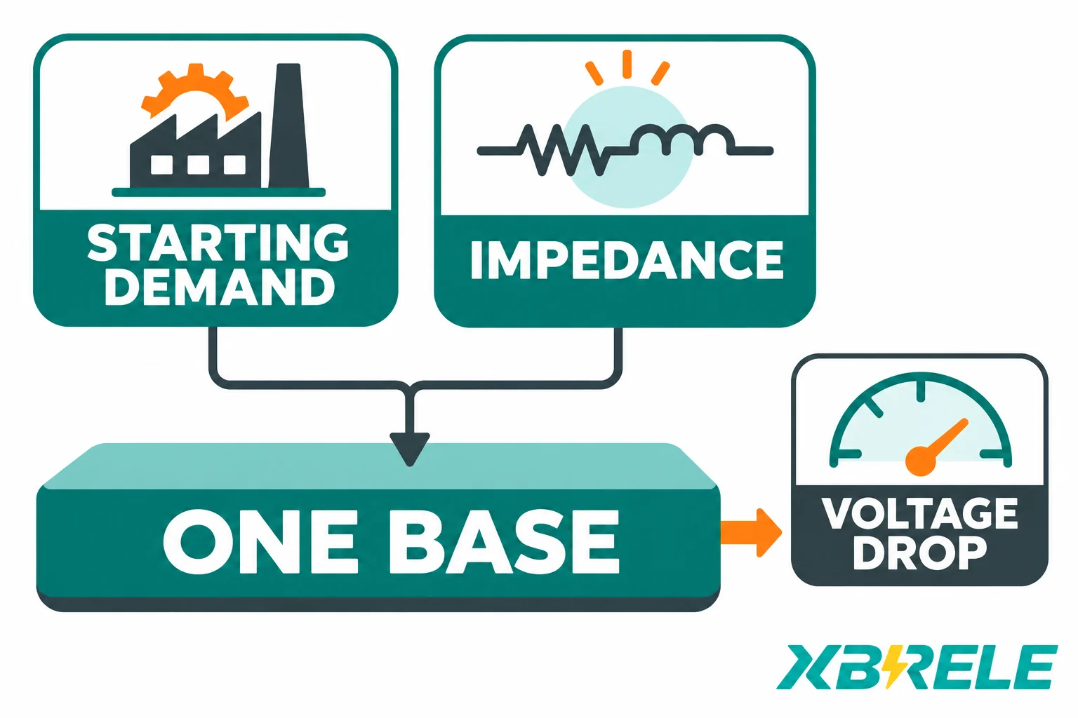
Figure 2 makes the bookkeeping point: the starting demand and the impedance must sit on the same base before they can be multiplied. Mixing a motor’s kVA with a transformer’s percentage impedance without a common base is the same class of error as adding amperes to ohms.
Two refinements belong in any real study but not in this estimate. First, the calculation should be a phasor sum rather than a scalar one, because the source, transformer and cable impedances have different angles and the motor current has its own phase angle. Second, the motor current is not fixed. For a direct-on-line induction motor at fixed slip and an approximately linear equivalent impedance, current falls roughly with terminal voltage, so the actual current during a deep dip is lower than the value taken at nominal voltage. That feedback makes the true result somewhat less severe than the fixed-current estimate for the motor’s own contribution, while the omitted upstream impedances make it more severe overall. A load-flow starting screen can iterate voltage and current. A dynamic study must also update slip, torque, speed and starter behaviour through the acceleration interval, using the manufacturer’s data.
The bus and the motor terminals are two different measurement points, separated by the feeder. Source and transformer together produce the bus dip. The feeder produces an additional drop between the bus and the motor. Reporting only one of them is how starting problems get missed in design and discovered at commissioning.

The bus voltage is what every other load sees. That is the number that decides whether contactors hold in, whether variable-speed drives trip on DC-bus undervoltage, whether PLCs and control relays reset, and whether the process survives. A start that is perfectly comfortable for the motor can still take a plant down through the other loads on the same bus. Motor terminal voltage is what decides whether the motor itself accelerates.
For the motor, the governing physics is short: at a given frequency and slip, electromagnetic torque is approximately proportional to the square of the applied voltage. At 0.85 pu terminal voltage, the torque available at any given slip is roughly 0.85² = 0.7225 of its nominal-voltage value. Treat that figure as arithmetic about the physics, not as a recommended acceptance level — projects set very different minimum voltages, and the right number depends on the load curve, the inertia and the permissible acceleration time.
Acceleration is where the voltage, torque and time questions meet. The motor accelerates on the difference between its torque curve and the load’s torque curve, and that surplus has to move the combined inertia. Reduce the voltage and the motor curve drops toward the load curve; the surplus narrows, acceleration slows, and the motor stays in the high-current region longer. For a load with demanding breakaway or running torque — whether approximately constant, rising or otherwise shaped over speed — the surplus can disappear entirely at some speed and the motor can stall at that speed while drawing sustained high current until the protective scheme acts. That is the mechanism behind the installation guide’s warning about stalling and slow acceleration: the damage is done by duration, not by the dip alone.
Starting method changes the shape of the same trade. A soft starter that limits current also reduces the voltage it applies to the motor, so the torque available falls roughly with the square of that reduced voltage as well. Aggressive current limiting buys a smaller bus dip and pays for it in starting time; if the limit is set too low for the load’s breakaway torque, the motor will not accelerate at all. Star-delta and autotransformer starting show the same trade in discrete steps, with a torque step at each transition. A suitable VFD controls motor voltage and frequency, and can provide the required starting torque under its current and control limits without the same direct-on-line supply-current event — but it introduces harmonic current, its own ride-through requirements and a different set of protection considerations, which is a different article’s worth of engineering.
When the study shows an excessive dip, the reflex is to specify a larger transformer. It is sometimes the right answer and often the most expensive way to solve a problem that lives somewhere else in the series path.
Increasing kVA at a given percentage impedance reduces the transformer’s ohmic impedance, so the drop it contributes to a given starting current falls. It also raises the fault level at the secondary terminals, which changes short-circuit withstand requirements, protective device ratings and coordination — a real consequence that has to be rechecked, not a side note. Specifying a lower percentage impedance at the same kVA achieves a similar reduction in dip with a similar fault-level penalty, while the resulting loss design, dimensions and energisation behaviour require separate manufacturer assessment. Lower short-circuit impedance alone does not prescribe magnetising inrush.

Figure 4 shows the three intervention zones — transformer, feeder, starting method — and the point is that each acts on a different term of the same sum. Working through the options on one comparison basis:
| Remedio | What it changes | What it does not fix, and what it costs |
|---|---|---|
| Larger transformer kVA at the same %Z | Reduces the transformer’s ohmic impedance contribution to the dip | Does nothing for a dominant source impedance or a long feeder; raises the transformer fault-current contribution; compare actual cost, footprint and losses for the candidate designs |
| Lower %Z at the same kVA | Same dip benefit, more directly targeted | Raises the transformer fault-current contribution; assess losses and energisation inrush separately; requires the works test to confirm the as-built value |
| Shorter or larger feeder, or parallel runs | Reduces the feeder’s contribution and therefore the gap between bus and motor terminal voltage | Primarily targets the downstream drop; recalculate the bus dip because motor current may change with terminal voltage; costs copper, tray space and routing effort |
| Staggering and interlocking starts | Prevents two motors from starting simultaneously, which is often the real worst case | Does nothing for a single motor’s own start; needs control-system logic and operating discipline |
| Soft starter with current limit | Cuts the current drawn, and therefore the dip | Cuts torque roughly with the square of the reduced voltage; lengthens the start; adds harmonics during the ramp |
| VFD | Decouples motor voltage and frequency from the bus; can limit the supply-side acceleration current within the selected drive and load duty | Adds harmonic filtering, drive and motor insulation considerations, and a new failure mode; higher capital cost |
| Mechanical unloading, clutch, reduced inertia | Lowers the torque the motor must develop to accelerate, shortening the high-current period | Requires process knowledge and possibly an operating-procedure change; not available for every machine |
| Upstream source upgrade | Raises the short-circuit level of the whole system, which lifts every downstream voltage | Often outside the plant’s control; expensive; may require utility approval and a long lead time |
Two observations follow from the table. A measure aimed at the transformer will not rescue a start that is limited by a weak upstream source. A feeder change primarily addresses motor-terminal drop; a bus-wide disturbance still requires evaluation of the upstream network and changed motor current. The correct remedy follows from which term of the sum dominates — and that is a question the calculation answers, not intuition.
The study is only as useful as its acceptance criteria. Agree them before running the numbers, because they determine which cases matter.
Define, in writing: the maximum permissible dip at the point of common coupling, set by the utility or by plant policy; the process tolerance for a disturbed bus; the hold-in and drop-out behaviour of contactors and relays on the same bus; the ride-through of drives and control systems; the minimum motor terminal voltage consistent with accelerating the load in the required time; the motor’s thermal withstand during acceleration, in terms of permissible starting time and starts per hour; and the system contingency to be studied — a start with one transformer out of service, on the weakest credible source, at maximum concurrent load.
Then build an event matrix rather than a single case. Rows are system states; columns are candidate starting events. Adapt the matrix to the actual topology and available methods: an outage state or alternative starter is studied only when applicable.
| State \ Event | Largest motor DOL | Largest motor with soft start | Reacceleration after bus transfer | Two motors in sequence |
|---|---|---|---|---|
| Normal source, normal loading | Requerido | Requerido | If the process uses transfer | Requerido |
| One transformer out of service | Requerido | Requerido | Requerido | Requerido |
| Weakest credible source level | Requerido | Requerido | Requerido | If applicable |
| Hot transformer, maximum ambient | Requerido | Requerido | If continuous duty | Requerido |
The study outputs that matter are time series, not single numbers: bus voltage versus time, motor terminal voltage versus time, motor current versus time, torque versus speed, speed versus time, acceleration time, and the resulting thermal dose for motor and transformer. Fault levels and protection coordination belong in the same deliverable, because the remedies that improve the dip tend to raise the fault current.
Two conditional scenarios show why the acceptance criteria and the remedy cannot be fixed in advance.
Case A — long feeder, strong source. A plant with a stiff utility supply and a 250 m cable run to a remote motor house. The bus dip is modest, well inside the utility’s limit, but the motor terminal voltage sags well below the bus because the feeder impedance dominates. A larger transformer would barely help: the drop is downstream of it. The targeted fix is the cable — larger cross-section, a parallel run, or relocating the motor control centre closer to the load — combined with a starting method that limits current if the cable solution is uneconomic.
Case B — weak upstream source, short cable. A plant fed from a long utility spur or from an on-site generator with limited short-circuit capability and significant transient source impedance. The motor sits close to the transformer, so the feeder is negligible, but the source impedance alone produces a dip that trips other loads on the bus. A larger transformer moves the number by less than expected, because the transformer is not where most of the impedance lives. The realistic options are a change of starting method, a source upgrade, or accepting a reduced starting duty through interlocking and sequencing.
Changing the transformer alone does not remove a dominant source or feeder constraint in either case. That is why the study — not a rule of thumb about motor kVA as a fraction of transformer kVA — has to come first.
Once the study fixes the requirement, the transformer enquiry becomes concrete. The purchase inputs are: rated kVA and voltage ratio; target percentage impedance with its tolerance, since the as-built value from the routine test governs the actual dip; tap range and tap position; cooling class and the corresponding rating under the specified ambient; guaranteed no-load and load losses at stated reference temperatures; enclosure type, IP rating and ventilation arrangement; altitude and ambient conditions; sound level; dimensions and general arrangement drawing; and cable box orientation and entry.
XBRELE’s cast-resin dry-type transformer range is described on the dry-type transformer catalogue page, which covers the catalogue position, loss figures at several reference temperatures, and ventilation and enclosure guidance. Because a catalogue table is not a specification for a particular unit, the figures that matter for a starting study — the agreed impedance, the guaranteed losses at the project’s reference temperature, the cooling rating and the general arrangement — should be requested for the specific unit rather than read off a published row. A supplier proposal on those terms tells you what the transformer will actually do in your calculation; it is not a guarantee that the motor will start.
If you are sizing a transformer for a project with a significant motor load, the sequence that avoids surprises is short:
For a concrete project, the dry-type transformer catalogue gives the range and the enquiry route; the fastest way to get a usable answer is to send the project brief with the motor data, the source short-circuit level, the cable schedule and the target impedance, and ask for a proposal stating impedance tolerance, guaranteed losses at the specified reference temperature and the cooling rating.
The two impedance references used above are the Schneider Electric Electrical Installation Guide pages on maximum voltage drop limits — which notes that steady-state limits do not cover motor starting — and on voltage drop calculation, which gives the balanced three-phase form ΔU = √3 I (R cos φ + X sin φ) L for the cable term.
Because the two checks are limited by different mechanisms. Running load is limited by temperature rise over minutes and hours, and the current involved is the motor’s full-load current. A start is limited by voltage over seconds, and the current involved is several times larger, flowing through the transformer, the source and the cable simultaneously. A transformer below rated running current may still satisfy its thermal check only after ambient, harmonics and cooling are considered; yet a motor drawing half the transformer’s rated current at a low starting power factor can still depress the bus more than the other loads or the utility limit allow. Thermal margin says nothing about impedance, and impedance is what sets the dip.
No — it is a first-order estimate, and only of one element. Multiplying the per-unit starting current by the per-unit transformer impedance gives the drop across the transformer windings under a stiff source, with no other load and no cable, and with the starting current held at its nominal-voltage value. A real study must add the source and feeder impedances in phasor form, account for the phase angle of the starting current, include the other loads drawing current from the same bus, and iterate because locked-rotor current itself falls as the terminal voltage falls. The single multiplication is useful for screening and for deciding whether a full study is warranted; it does not establish the final starting performance.
It reduces the current drawn and therefore the dip, but it does not necessarily solve anything. Torque falls roughly with the square of the applied voltage, so a starting method that halves the motor voltage leaves about a quarter of the torque available. If the load’s breakaway torque or its rising torque curve needs more than that, the motor will not accelerate, or will accelerate so slowly that the high current lasts far longer than it would have at full voltage — a worse thermal outcome than the dip you were trying to avoid. Its suitability depends on the complete torque-speed and acceleration study; neither a low inertia nor a reduced current alone establishes an acceptable start.
Several parameters move between the two events. The transformer is colder on the first start after a long shutdown, so its winding resistance is marginally lower but its thermal headroom is larger. The motor is also cold, which changes its permissible starting time. The driven machine may not be — a pump that has drained, a conveyor that has settled, a compressor with residual pressure all present a different load curve from the one in the steady operating state. And the bus loading at the moment of the start is rarely identical, since other plant may be running. For a study, the conservative practice is to model both: evaluate cold and hot motor starts, transformer temperatures, source states and concurrent loads separately. A repeat hot start can have less motor thermal margin, while maximum and minimum fault duties require their own specified network and temperature cases.