Need Full Specifications?
Download our 2025 Product Catalog for detailed drawings and technical parameters of all switchgear components.
Get CatalogDownload our 2025 Product Catalog for detailed drawings and technical parameters of all switchgear components.
Get CatalogDownload our 2025 Product Catalog for detailed drawings and technical parameters of all switchgear components.
Get Catalog
Your short-circuit study arrives showing 31.2 kA prospective fault current at the main bus. The switchgear datasheet lists two ratings: Icw = 31.5 kA (3s) and Breaking Capacity = 40 kA. Which number determines if this breaker fits your application?
Both matter—but they guard against entirely different failure modes.
Confusing Icw with interrupting kA leads to one of two costly outcomes: undersized equipment that fails during coordination events, or oversized equipment that drains procurement budgets unnecessarily. This guide separates the two parameters at the physics level, shows exactly which fault study values map to each rating, and provides margin rules field-tested across industrial, commercial, and utility installations.
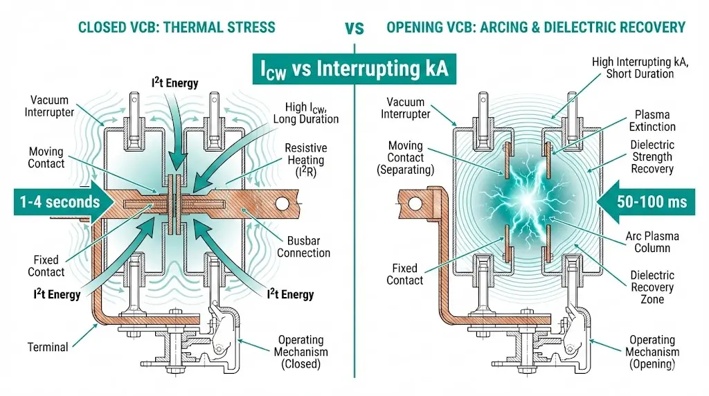
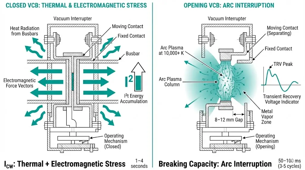
Icw (short-time withstand current) represents the maximum current a closed circuit breaker can carry for a specified duration without sustaining thermal or mechanical damage. The device remains closed throughout—no interruption occurs. Per IEC 62271-200, medium-voltage switchgear assemblies must withstand rated Icw for either 1 second or 3 seconds, depending on protection coordination requirements. Typical values range from 16 kA to 50 kA.
The physics center on I²t energy accumulation. A 31.5 kA current sustained for 3 seconds deposits nine times more energy into conductors and contacts than the same current for 1 second. Busbars expand. Joints loosen. Contacts weld if spring pressure proves insufficient.
Interrupting kA (breaking capacity) defines the maximum fault current the device can safely interrupt while opening under load. This dynamic rating accounts for contact separation, arc plasma formation exceeding 10,000 K, and dielectric recovery after arc extinction. IEC 62271-100 specifies test sequences for vacuum circuit breakers at rated breaking capacity, with common values spanning 20 kA to 63 kA.
The stress regimes differ fundamentally. Icw involves seconds of thermal punishment. Interrupting involves milliseconds of arc violence.
The comparison table below captures the essential distinctions that govern vacuum circuit breaker specification decisions:
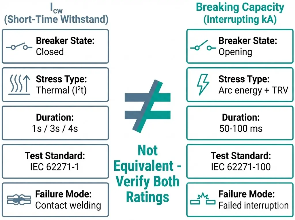
| Parameter | Icw | Breaking Capacity |
|---|---|---|
| Breaker state | Closed (conducting) | Opening (interrupting) |
| Stress type | Thermal (I²t), electromagnetic forces | Arc energy, transient recovery voltage |
| Duration | 1s, 3s, or 4s (per IEC 62271-1) | 50–100 ms (3–5 cycles) |
| Typical ratio | Base value | 1.25–1.6× Icw |
| Test standard | IEC 62271-1 | IEC 62271-100 |
| Failure consequence | Contact welding, busbar damage | Failed interruption, arc flash |
Why does breaking capacity often exceed Icw on the same breaker? Vacuum interrupters extinguish arcs within 30–50 ms—far shorter than the 1–4 second Icw exposure window. Less time means less thermal accumulation during the breaking operation itself.
Critical warning: A 40 kA breaking capacity does not guarantee 40 kA withstand capability. Many medium-voltage VCBs carry breaking ratings 1.25–1.6× higher than their Icw ratings. Never assume equivalence without checking the datasheet.
[Expert Insight: Field Verification Practices]
- Always request both Icw AND breaking capacity on quotation requests—vendors sometimes omit Icw
- Verify test laboratory accreditation (KEMA, CESI, XIHARI) on type test certificates
- Check that tested X/R ratio matches your system characteristics (IEC assumes X/R = 17)
- For generator applications, confirm Icw duration covers your protection coordination time
Fault studies generate multiple current values. Selecting the wrong one creates specification errors that pass through procurement undetected—until commissioning reveals the mismatch.
| Study Output | Description | Use For |
|---|---|---|
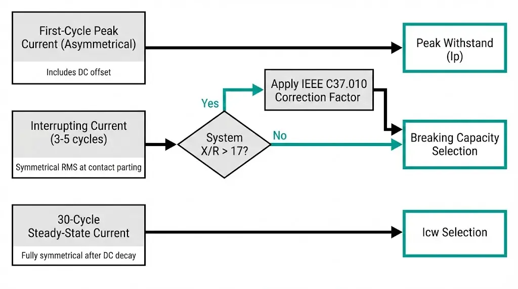
| First-cycle peak (asymmetrical) | Includes DC offset, highest instantaneous value | Peak withstand (Ip) verification only |
| Interrupting current (3–5 cycles) | Symmetrical RMS at moment of contact parting | Breaking capacity selection |
| 30-cycle steady-state | Fully symmetrical after DC decay | Icw selection |
The first-cycle asymmetrical peak—often the largest number in your study—applies only to mechanical bracing and peak withstand ratings. Using it for breaking capacity selection oversizes equipment by 50–100%.
High X/R ratios near large transformers or generators slow DC component decay, producing higher asymmetrical peaks and sustained current levels. IEC 62271-100 test procedures assume X/R = 17. If your system exceeds this value, request adjusted test certificates or apply correction factors per IEEE C37.010 methodology.
Before specifying any switchgear, confirm your study includes:
For deeper understanding of how these values interact with VCB rating parameters, comprehensive technical documentation helps bridge the gap between study output and specification language.
Breaking capacity dominates most specification discussions. But Icw becomes the critical rating when the circuit breaker must carry fault current without tripping—waiting for upstream protection to clear the fault first.
The tie breaker remains closed while a feeder breaker clears a downstream fault. If feeder relay time plus breaker operating time totals 600 ms, the tie breaker experiences fault current for that entire duration. Its Icw must exceed the through-fault contribution for at least 1 second.
During parallel transformer operation, a bus fault requires coupler breakers to carry combined source contributions until zone-selective interlocking operates. The coupler never trips—it just survives.
Utility coordination often demands delayed generator breaker clearing to allow excitation system response. Three-second Icw requirements appear frequently in interconnection specifications.
At a 12 kV industrial substation, the original specification called for 25 kA breaking capacity—adequate for the 22 kA prospective fault current. However, the protection coordination study revealed the main breaker needed 1.5-second delay for selectivity with utility relaying.
The problem: 25 kA/1s Icw couldn’t survive the coordination window.
The resolution required upgrading to switchgear with 31.5 kA/3s Icw capability—a 35% cost increase that would have been avoided had protection and equipment specifications been coordinated from project initiation.
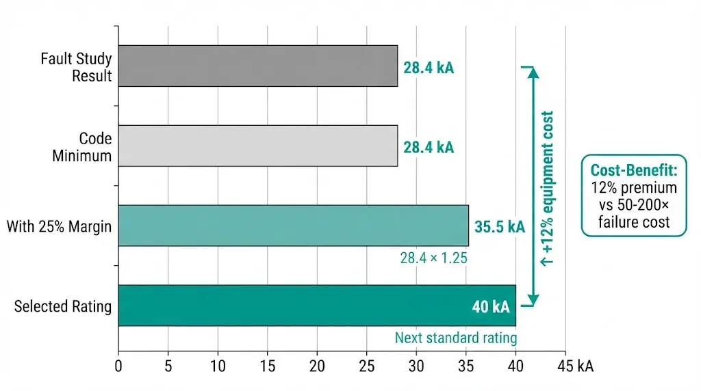
Codes establish minimum requirements. Successful installations apply margins that account for real-world uncertainty.
| Application | Breaking Margin | Icw Margin | Rationale |
|---|---|---|---|
| Industrial (stable load) | ≥15% | ≥15% | Covers measurement uncertainty |
| Commercial (expansion planned) | ≥25% | ≥25% | HVAC upgrades, EV charging |
| Utility substation | 20–40% | Match breaking rating | Long service life, multiple reconfigurations |
| Data center | ≥25% | ≥25% | Rapid load growth common |
| Generator interconnection | ≥20% | ≥ breaking rating | Extended clearing times |
The VS1 series VCB offers multiple Icw/breaking capacity combinations specifically designed to match diverse coordination requirements without forcing unnecessary upgrades.
Upgrading from 31.5 kA to 40 kA breaking capacity typically adds 8–15% to switchgear cost. Extending Icw from 1s to 3s rating adds another 10–20% due to heavier busbars and contact structures. These premiums seem significant until compared against alternatives: a failed interruption or thermal damage event costs 50–200× more when accounting for arc flash damage, production downtime, and potential injury liability.
[Expert Insight: Margin Optimization]
- For facilities with 10+ year planning horizons, 25% margin typically proves cost-effective versus future retrofits
- Generator interconnection projects should verify utility Icw requirements before equipment procurement—some utilities mandate 4-second ratings
- Data centers with planned UPS expansions should model fault contribution from future battery systems
| Error | Consequence | Prevention |
|---|---|---|
| Specifying breaking capacity only | Icw overlooked, coordination fails | Always specify both ratings with duration |
| Using first-cycle current for breaking selection | Equipment oversized 50–100%, budget wasted | Use symmetrical interrupting current |
| Outdated fault study | Ratings insufficient after facility expansion | Require study dated within 24 months |
| Icw duration not stated | Vendor assumes 1s when 3s needed | State duration explicitly in specification |
| Ignoring X/R ratio deviation | Standard ratings inadequate for system | Request adjusted test certificates |
Include this language in RFQ documents to eliminate ambiguity:
“Vacuum circuit breaker shall have rated short-circuit breaking capacity of [X] kA and short-time withstand current (Icw) of [Y] kA for [Z] seconds duration, type-tested per IEC 62271 series standards by an accredited laboratory.”
Selecting the right combination of Icw and breaking capacity requires equipment options—not compromises. XBRELE manufactures vacuum circuit breakers across the full medium-voltage range:
Connect with our technical team at XBRELE vacuum circuit breaker manufacturer to review your short-circuit study and receive rating recommendations matched to your protection coordination requirements.
Q: What determines whether Icw or breaking capacity governs my breaker selection?
A: Protection coordination timing determines precedence. If your breaker must carry fault current while waiting for upstream devices to clear (coordination delay > 0.5s), Icw typically governs. If your breaker is the first to interrupt, breaking capacity takes priority.
Q: How do I convert first-cycle asymmetrical current to breaking capacity requirement?
A: You don’t convert directly. Use the symmetrical RMS interrupting current value from your fault study (calculated at 3–5 cycles after fault initiation), not the asymmetrical peak. The peak value applies only to mechanical withstand verification.
Q: Can a breaker with 40 kA breaking capacity withstand 40 kA for 3 seconds?
A: Not necessarily. Breaking capacity and Icw are independently tested parameters. Many VCBs have breaking ratings 1.25–1.6× higher than their Icw ratings. Always verify both values on the manufacturer’s datasheet.
Q: What margin should I apply for a data center with planned expansion?
A: Apply minimum 25% margin to both breaking capacity and Icw ratings. Model fault contributions from planned UPS systems and generator additions in your study before finalizing specifications.
Q: How often should short-circuit studies be updated?
A: Update studies every 24 months or whenever significant changes occur—new utility transformer connections, generator additions, major load increases, or system reconfigurations. Outdated studies represent one of the most common sources of rating mismatches.
Q: Does X/R ratio affect both Icw and breaking capacity selection?
A: Yes, but differently. High X/R ratios (>17) increase asymmetrical peaks affecting breaking duty and sustain higher current levels longer, affecting Icw thermal stress. Request manufacturer guidance when your system X/R significantly exceeds standard test assumptions.