Need Full Specifications?
Download our 2025 Product Catalog for detailed drawings and technical parameters of all switchgear components.
Get CatalogDownload our 2025 Product Catalog for detailed drawings and technical parameters of all switchgear components.
Get CatalogDownload our 2025 Product Catalog for detailed drawings and technical parameters of all switchgear components.
Get Catalog
A 50 ms voltage dip during a grid disturbance can drop an electrically held contactor—disconnecting a 2,000 kVAR capacitor bank mid-cycle and triggering damaging inrush currents when power returns. That same disturbance leaves a mechanically latched contactor undisturbed, contacts firmly closed, load uninterrupted.
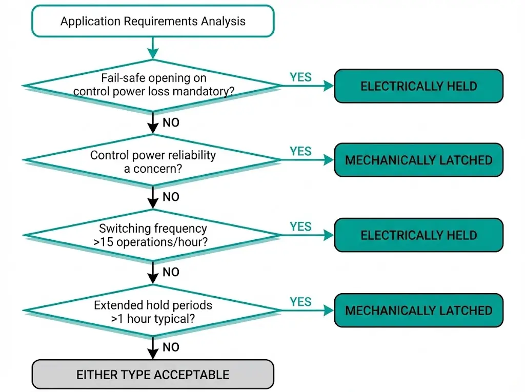
This behavioral difference defines the core selection criteria: electrically held contactors require continuous coil energization to maintain closure, while mechanically latched contactors hold position through physical latch mechanisms or permanent magnets after receiving only a momentary pulse. Neither design is universally superior. The right choice depends entirely on which failure mode your application cannot tolerate.
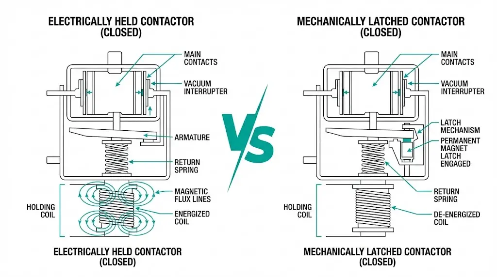
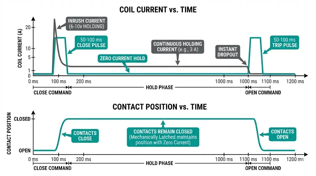
Electrically held contactors maintain contact closure through continuous electromagnetic force. The coil remains energized throughout the entire ON period, typically drawing 5–15 W of holding power depending on contactor size and voltage rating. Remove coil power—intentionally or due to supply failure—and the contacts immediately open under spring return force. Contact state directly mirrors coil state: energized equals closed, de-energized equals open.
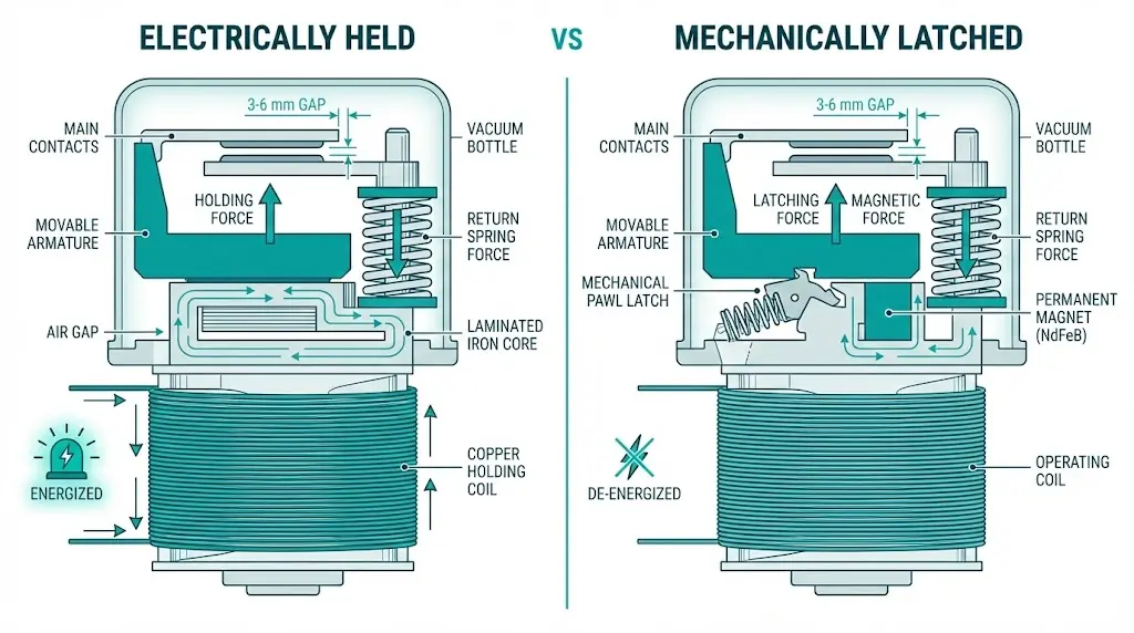
Mechanically latched contactors operate on a bistable principle requiring fundamentally different control logic. A momentary pulse (typically 50–100 ms) energizes the closing coil, driving contacts to the closed position. At the end of travel, one of three mechanisms locks the armature in place:
Once latched, the coil de-energizes completely. Contacts remain closed with zero continuous power consumption—a characteristic that eliminates coil heating entirely.
The control circuit implications differ substantially. Electrically held units use simple two-wire or three-wire control with maintained contact logic. Mechanically latched contactors require either dual coils (separate close and open windings) or a single bipolar coil with polarity reversal—adding wiring complexity but eliminating continuous current flow and associated panel heat generation.
The physics behind each holding mechanism creates distinct failure prevention characteristics. Understanding these differences allows precise matching of contactor type to application vulnerability.
| Scenario | Electrically Held | Mechanically Latched |
|---|---|---|
| Voltage dip to 70% for 100 ms | Contacts DROP—load disconnected | Contacts REMAIN CLOSED—no interruption |
| Complete control power loss | Immediate spring-return opening | Contacts hold indefinitely in last state |
| Control fuse failure | Load disconnected | No effect on contact position |
| Failure Prevented | Uncontrolled restart after power restoration | Nuisance tripping during grid disturbances |
Field data from mining substations confirms this distinction. Facilities experiencing more than five voltage sags monthly below 85% nominal reported 40–60% fewer nuisance trips after converting capacitor switching contactors to mechanically latched designs.
Electrically held coils dissipate 5–15 W continuously during closure. In enclosed panels at ambient temperatures exceeding 40°C, coil temperatures can approach Class F insulation limits (155°C). Thermal cycling accelerates insulation degradation—approximately 50% life reduction for every 10°C rise above rated temperature.
Mechanically latched contactors eliminate this failure mode entirely. The coil energizes only during state transitions, reducing duty cycle from 100% to less than 0.1% in typical applications. Comparative testing across Gulf Coast petrochemical facilities showed zero coil-related failures in 200+ mechanically latched units over five years, versus 8% annual coil replacement rates for electrically held alternatives in identical service conditions.
Electrically held contactors provide inherent fail-safe behavior aligned with IEC 60947-4-1 requirements for motor starters. Loss of control power causes immediate contact opening within 20–50 ms—essential for emergency stop circuits where uncontrolled equipment restart could endanger personnel.
Mechanically latched contactors maintain their last commanded state regardless of control power status. This characteristic prevents nuisance tripping but requires additional safety circuit design to ensure positive disconnection during emergencies.
[Expert Insight: Control Power Quality Assessment]
- Measure voltage sag frequency and duration at the contactor control supply point before specifying holding mechanism type
- Facilities with >3 sags/month below 85% nominal voltage benefit from mechanically latched contactors in continuous process applications
- Install power quality meters on control circuits for 30 days minimum to capture representative disturbance data
- Consider UPS-backed control supplies as an alternative to mechanically latched contactors where fail-safe opening remains mandatory
Recommended: Mechanically latched
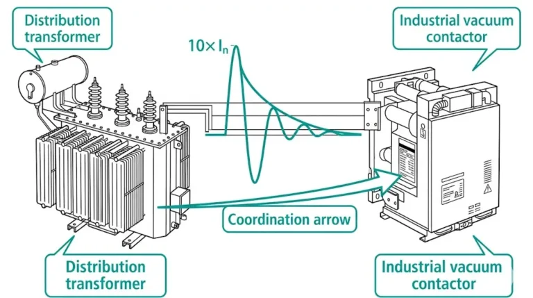
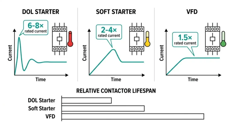
Capacitor energization produces inrush currents reaching 15–20× rated current for the first half-cycle. Each unnecessary switching operation—caused by voltage dip dropout and subsequent re-closure—subjects contacts to repeated inrush stress, accelerating erosion rates. Remote capacitor bank installations often experience less reliable control power, compounding dropout risk.
For capacitor switching applications requiring bistable operation, the JCZ series vacuum contactor provides mechanical latching configurations rated for high-frequency capacitor duty across 3.3–12 kV systems.
Recommended: Electrically held (jogging) / Application-dependent (starting)
Jogging operations demand instant response to start/stop commands. Mechanically latched contactors introduce pulse delays incompatible with rapid reversing cycles. Safety circuits typically mandate fail-safe disconnection on E-stop activation—a requirement inherently satisfied by electrically held designs.
Exception: Large motors exceeding 400 kW at remote pump stations benefit from latched contactors. Control power dips that would cause nuisance trips with electrically held units can force extended restart sequences, thermal stress from repeated starting, and production losses exceeding the cost of additional safety circuit complexity.
Recommended: Based on installation location
Transformer energization inrush reaches 8–12× rated current for 100 ms. Repeated energization from nuisance dropout doubles thermal and mechanical stress on windings and bushings.
Recommended: Mechanically latched
Long duty cycles (minutes to hours) make continuous coil power wasteful. A 60 W coil operating 8,760 hours annually consumes 526 kWh—multiplied across dozens of heating contactors in large facilities, this represents substantial operating cost. Pulse-only operation eliminates both energy consumption and thermal cycling stress on coil insulation.
Field observation: Maintenance technicians occasionally misdiagnose mechanically latched contactors as “stuck” when the trip circuit fails. Clear panel labeling—LATCHED TYPE / REQUIRES TRIP PULSE TO OPEN—prevents confusion and unnecessary contactor replacement.
| Parameter | Electrically Held | Mechanically Latched |
|---|---|---|
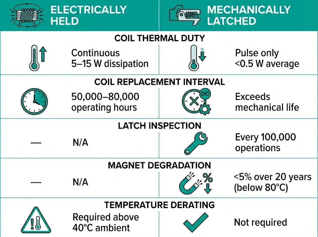
| Thermal duty | Continuous (5–15 W) | Pulse only (<0.5 W average) |
| Insulation stress | Continuous thermal aging | Minimal—pulse heating only |
| Typical replacement interval | 50,000–80,000 operating hours | Often exceeds mechanical life of contactor |
Pawl/cam latches show measurable wear after 100,000+ operations. Inspection intervals should decrease in high-cycling applications. Dusty or contaminated environments accelerate wear—lubrication intervals may require adjustment from standard 2-year cycles to 6–12 months.
Permanent magnet latches experience no mechanical wear. Magnet demagnetization remains negligible over 25+ years at operating temperatures below 80°C. However, exposure to external magnetic fields or temperatures exceeding magnet grade limits (typically 150°C for high-grade NdFeB) can cause irreversible force reduction.
Both holding mechanisms use identical vacuum interrupter technology for arc extinction. Contact erosion rates, dielectric recovery characteristics, and interrupting capacity remain unaffected by the holding method. For vacuum interrupter wear indicators and maintenance scheduling, see the vacuum circuit breaker ratings guide.
[Expert Insight: Specification Checklist]
- Specify holding mechanism type explicitly on procurement documents—“vacuum contactor” alone is insufficient
- Request coil power consumption data (holding VA for electrically held; pulse energy in joules for mechanically latched)
- Verify auxiliary contact configuration matches control system requirements before ordering
- For mechanically latched units, confirm trip coil voltage and pulse duration requirements match available control supply
| Application | Recommended Type | Primary Selection Reason |
|---|---|---|
| Capacitor banks (remote sites) | Mechanically latched | Ride-through prevents repeated inrush |
| Motor jogging/reversing | Electrically held | Rapid response + inherent fail-safe |
| Large motors (remote pumping) | Mechanically latched | Control power reliability |
| Furnace/heating loads | Mechanically latched | Energy savings + reduced coil stress |
| Safety-critical disconnection | Electrically held | Automatic opening on control loss |
| High-frequency switching (>20/hr) | Electrically held | No latch mechanism wear |
The selection question reduces to one fundamental choice: which failure consequence is unacceptable in your specific application?
XBRELE manufactures both vacuum contactor configurations across the 3.3–12 kV range, with mechanical latching and electrically held variants available in matching frame sizes for standardized panel designs.
For OEM integration, custom control voltage requirements, or technical selection support based on your specific failure-mode priorities, explore XBRELE’s vacuum contactor manufacturing capabilities.
Can a mechanically latched contactor be converted to electrically held operation?
No—the holding mechanism is integral to the contactor’s magnetic circuit and mechanical assembly. Conversion requires complete contactor replacement; specify the correct type during procurement.
What happens if both the close and trip coils fail on a mechanically latched contactor?
Contacts remain in their last position indefinitely. Critical applications should include upstream protective devices capable of interrupting the circuit independently of the contactor’s trip coil function.
How much energy do electrically held contactors consume annually?
A typical 10 W holding coil operating continuously consumes approximately 88 kWh per year. Facilities with dozens of contactors in continuous duty may see meaningful cost reduction from mechanically latched alternatives.
Which contactor type handles vibration better?
Electrically held contactors maintain continuous electromagnetic clamping force that counteracts vibration. Mechanically latched units may require vibration-rated latch mechanisms (tested per IEC 60068-2-6) for mobile or high-vibration installations exceeding 2g acceleration.
Do permanent magnet latches weaken over time?
Modern NdFeB magnets retain greater than 95% of initial strength after 20+ years at temperatures below 80°C. Demagnetization risk increases significantly above 120°C or with exposure to strong external magnetic fields.
Can mechanically latched contactors provide emergency stop functionality?
Yes, but requires a reliable trip circuit. Unlike electrically held contactors that open automatically on control power loss, mechanically latched units need positive trip coil energization. E-stop circuits must include dedicated power supplies or fail-safe trip mechanisms.
Which type requires less maintenance?
Mechanically latched contactors eliminate coil thermal aging but introduce latch mechanism inspection requirements. Electrically held contactors have simpler mechanisms but require coil condition monitoring. Total maintenance burden depends on operating environment and switching frequency rather than holding mechanism type alone.
Authority reference: For standard definitions and test context, see IEC 62271-106 publication page.