Need Full Specifications?
Download our 2025 Product Catalog for detailed drawings and technical parameters of all switchgear components.
Get CatalogDownload our 2025 Product Catalog for detailed drawings and technical parameters of all switchgear components.
Get CatalogDownload our 2025 Product Catalog for detailed drawings and technical parameters of all switchgear components.
Get Catalog
In medium-voltage distribution systems (3.6 kV to 12 kV), switching devices are often misunderstood. While vacuum circuit breakers (VCBs) get the spotlight for fault protection, the vacuum contactor is the true workhorse of industrial automation. Designed for high-frequency switching—often executing thousands of operations per month—the vacuum contactor bridges the gap between simple manual disconnects and heavy-duty circuit protection.
However, treating a contactor like a circuit breaker is a recipe for failure. From misapplying utilization categories to botching fuse coordination, the engineering nuances determine whether a motor starter lasts twenty years or fails during commissioning. This guide dissects the anatomy, ratings, and critical control schemes of medium-voltage vacuum contactors for engineers and procurement specialists.
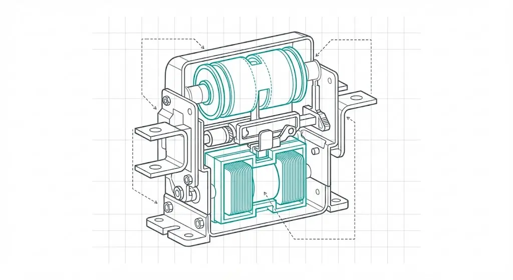
A medium-voltage vacuum contactor is an electromagnetic switching device engineered specifically for endurance. Unlike a circuit breaker, which utilizes a stored-energy spring mechanism to interrupt massive short-circuit currents occasionally, a contactor uses a solenoid-driven magnetic system to switch load currents repeatedly. This fundamental difference prioritizes mechanical life—typically rated for 300,000 to 1,000,000 cycles—over the raw fault-clearing power of a VCB.
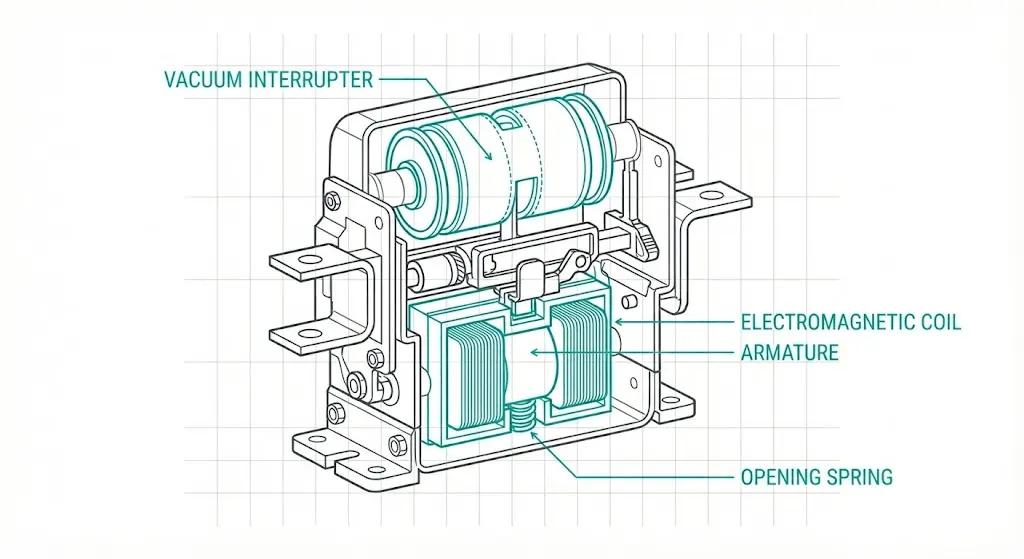
The core of the device is the vacuum interrupter (VI), a sealed ceramic chamber housing the contacts. When the electromagnetic coil is energized, it pulls the armature, closing the contacts against a calibrated pressure spring. This spring is critical: it ensures low contact resistance during normal operation and prevents contact separation during the high electromagnetic forces of an inrush event. When the coil is de-energized, return springs force the armature back, separating the contacts to break the circuit.
Inside the interrupter, the environment is maintained at a high vacuum, typically between 10-2 Pa and 10-4 Pa. When the contacts separate, the metal vapor arc generated by the load current diffuses rapidly into this vacuum. Because there is no gas to ionize, the dielectric strength across the open contact gap recovers almost instantly—often within microseconds of the current zero-crossing. This allows the contactor to extinguish the arc with a relatively small contact gap, usually 4 mm to 8 mm depending on the voltage rating (7.2 kV vs. 12 kV).
It is critical to distinguish this mechanism from that of a vacuum circuit breaker. A VCB uses a mechanical latch and trip system designed to hold contacts closed even if control power is lost, only opening when a protective relay signals a fault. A standard vacuum contactor is “electrically held,” meaning it will open automatically if the control voltage drops, making it inherently fail-safe for motor control applications where restarting unexpectedly could be dangerous.
Understanding this internal architecture of the vacuum interrupter is the first step in matching the device to its application.
[Expert Insight] Why Contact Material Matters
- Circuit Breakers (CuCr): VCBs typically use Copper-Chromium contacts. These are optimized for high dielectric strength to interrupt 25kA+ faults but can weld if switched too frequently.
- Contactors (WCAg): Vacuum contactors often use Tungsten-Carbide-Silver. This material is harder and more resistant to erosion during the repetitive “bouncing” of motor starting, though it has lower ultimate breaking capacity.
- The Trade-off: You cannot swap interrupters between a breaker and a contactor. The metallurgy is tuned to the duty cycle (Protection vs. Endurance).
A datasheet rating of “400 A” is effectively meaningless without the context of the utilization category. Defined under IEC 62271-106 (adapting concepts from IEC 60947-4-1), these categories dictate the severity of the electrical stress placed on the contacts. Specifying the wrong category is the leading cause of premature contact welding in industrial plants.
AC-3 is the standard category for squirrel-cage motors: starting the motor and switching it off only after it has reached full speed. Here, the contactor handles high inrush current upon closing but breaks a relatively low running current.
AC-4, conversely, involves “inching” or “plugging”—stopping the motor while it is still accelerating, or reversing it rapidly. This is common in cranes, hoists, and mining conveyors.
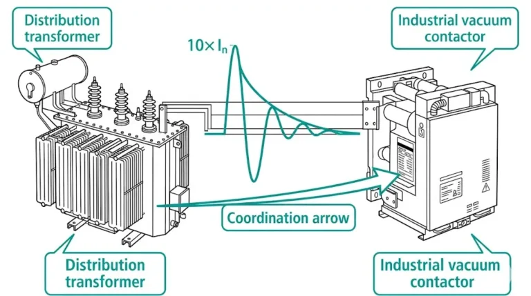
In an AC-3 application, the contactor must typically withstand making currents of approximately 6 × In (rated operational current) but breaks only 1 × In. In an AC-4 application, the contactor must both make and break the locked-rotor current. This means the interrupter interrupts 6 × In at a highly inductive power factor (often cos φ ≤ 0.35). This generates significantly more arc energy, increasing contact erosion rates by a factor of 10 or more compared to AC-3 duty.
Switching capacitor banks presents a different physical challenge. Unlike motors (inductive loads) which resist current change, capacitors resist voltage change, acting almost like a short circuit at the instant of energization.
When a single capacitor bank is energized, the inrush current is limited only by grid impedance. However, in back-to-back switching (energizing a bank in parallel with one already energized), high-frequency inrush currents can flow between the banks. These transients can reach peak values of 100 × In with frequencies exceeding 2,500 Hz. Standard contact materials like Copper-Tungsten (CuW) designed for motor switching may overheat or weld under these conditions.
Engineers specifying capacitor duty contactors must verify the unit is rated for Class C2 or AC-6b. These often require specialized contact materials and higher mechanical latching forces to prevent contact bounce during the massive electromagnetic repulsion generated by the inrush.
A standalone vacuum contactor typically has a maximum breaking capacity of only 4 kA to 6 kA. In modern industrial networks where fault currents often exceed 31.5 kA, the contactor cannot safely interrupt a short circuit. Attempting to do so would result in the vacuum interrupter exploding or the contacts welding solid. To solve this, medium-voltage motor starters employ the “F-C” architecture: high-breaking-capacity current-limiting fuses (HRC fuses) handle the short circuits, while the contactor manages switching and overloads.

The critical engineering challenge is defining the take-over point. This is the specific current value on the Time-Current Characteristic (TCC) curve where the fuse clearing time becomes faster than the contactor’s opening time.
For safe coordination, the take-over current (Ito) must occur at a value lower than the contactor’s rated breaking capacity. Consider a system where the contactor can break 4 kA. If a fault current of 10 kA occurs, the fuse must melt and clear the circuit in less time than it takes for the contactor to unlatch and separate its contacts (typically 30 ms to 50 ms). If the protection relay signals the contactor to open at 10 kA before the fuse acts, the contactor will attempt to interrupt a current beyond its rating, leading to failure.
IEC 62271-106 mandates specific coordination types (Type A and Type C). Type C coordination, preferred for critical protection schemes involving vacuum contactors, ensures that after a short-circuit event cleared by the fuses, the contactor remains operational without requiring repair or contact replacement.
For detailed standard definitions, refer to IEC 62271-106 High-voltage switchgear and controlgear which governs these contactor specifications.
[Expert Insight] The “Striker Pin” Trap
- Mechanism: Most MV fuses have a striker pin that pops out when the fuse blows. This pin hits a linkage bar to trip the contactor mechanically.
- The Risk: If the contactor opens simultaneously with the fuse clearing a low-magnitude fault, the arc might transfer to the contactor contacts if the fuse hasn’t fully extinguished it.
- The Fix: Ensure the mechanical linkage has a slight delay or that the fuse selection prevents operation in the “forbidden band” (currents that melt the fuse element but don’t clear the arc quickly).
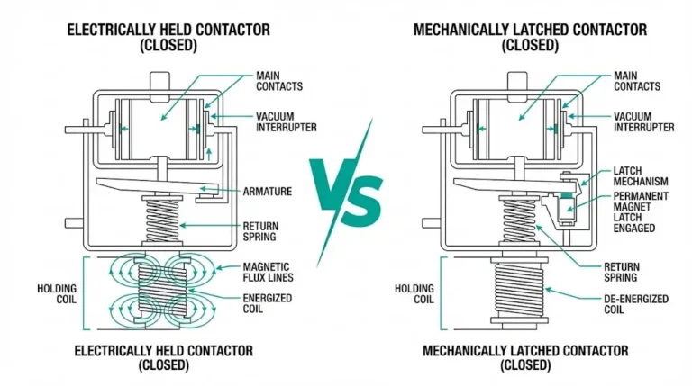
The operating mechanism defines how the device manages energy to close the contacts and, crucially, how it maintains that state. While vacuum circuit breakers use stored-energy springs, contactors use electromagnetic actuation, dividing them into two structural categories.
This is the standard for motor starters. The closing coil must remain energized to keep the contacts closed. The solenoid overcomes the opening spring force and holds the armature against the magnet core.
To prevent coil burnout, these mechanisms employ an “economizer” circuit. The coil draws a high inrush power (e.g., 800–1500 W) for approximately 100 ms to close the gap, then switches to a low-power holding mode (e.g., 40–80 W) to maintain contact pressure without overheating. The primary advantage is the inherent fail-safe feature: if control power is lost or drops below the drop-out threshold (typically 40% – 60% of Un), the contactor opens automatically. This protects motors from restarting unexpectedly when power is restored.
Mechanically latched contactors behave more like circuit breakers. The closing coil is energized only momentarily to pull the armature in. Once closed, a mechanical latch locks the mechanism, and the coil is de-energized.
To open the contactor, a separate trip coil must be energized to release the latch. This design consumes zero power in the steady state and ensures the switch remains closed even during severe voltage dips or complete auxiliary power loss. This makes latched contactors ideal for transformer feeders or critical distribution circuits where continuity of service takes precedence over motor safety logic. However, the mechanical complexity is higher, and the mechanism is typically rated for fewer mechanical operations (e.g., 100,000) compared to the electrically held units.
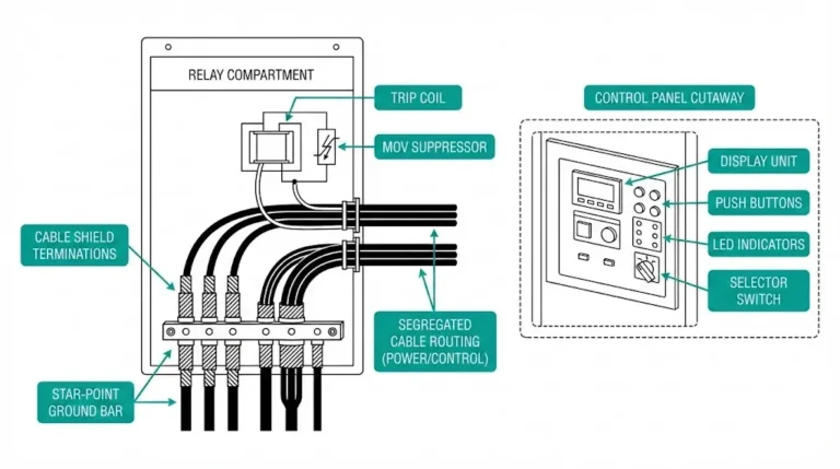
While the primary terminals handle kilovolts, the reliability of the device depends entirely on the secondary control circuit. In industrial switchgear panels and Motor Control Centers (MCC), the control logic bridges the gap between the operator’s push-button and the high-voltage switching action.
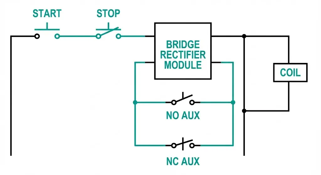
Most medium-voltage vacuum contactors employ DC operating coils, even if the substation supply is AC. AC solenoids are prone to “hum” or chatter—mechanical vibration caused by the magnetic flux passing through zero. This vibration causes fretting wear on the armature and micro-movement of the contacts.
To eliminate this, manufacturers integrate a bridge rectifier module directly into the contactor chassis. This converts the incoming AC control supply (e.g., 230 V AC) into a pulsating DC voltage for the coil. The DC magnetic field provides a constant, silent holding force. However, this introduces a maintenance variable: the rectifier is a semiconductor component sensitive to voltage surges. When troubleshooting a contactor that refuses to close, the rectifier is often the culprit.
The secondary circuit manages safety through auxiliary contacts (NO/NC) mechanically linked to the armature. These are used for:
For engineers designing these control circuit schematics, “anti-pumping” logic is mandatory for latched contactors to prevent the device from cycling destructively if close and trip commands are issued simultaneously.
Standard specifications are calibrated for “normal service conditions,” typically assuming an altitude < 1,000 meters and temperatures of -5°C to +40°C. Real-world deployments in mining or high-altitude infrastructure often violate these baselines.
High altitude does not affect the internal vacuum interrupter, but it drastically reduces the dielectric strength of the external air clearance.
According to Paschen’s Law, the breakdown voltage of a gas gap is a function of the product of pressure and gap distance. At 3,000 meters, atmospheric pressure drops to approximately 70 kPa (compared to 101.3 kPa at sea level). This reduces the external dielectric withstand capability of the contactor. To maintain the same safety margin (e.g., 75 kV BIL for a 12 kV system), engineers must apply an altitude correction factor (Ka) to the insulation requirements. For a site at 2,000 meters, the required withstand voltage test value typically increases by a factor of Ka = 1.13, meaning the equipment must be tested at roughly 85 kV instead of 75 kV at sea level.
In heavy industrial facilities, large motor starts can cause momentary voltage dips (sags). If a vacuum contactor’s coil is sensitive to these fluctuations, the magnetic holding force may weaken.
A standard solenoid is designed to operate reliably between 85% and 110% of its rated control voltage (Un). If the voltage drops below 85% (e.g., < 187 V on a 220 V circuit), the armature may not fully seal against the core. This results in "contact hover," where the main contacts touch but lack the full spring pressure required to handle the current. This leads to localized overheating and welding. High-performance "wide-range" coils are available for unstable grids, capable of maintaining closure down to 70% Un.
The governing standard for these environmental corrections is typically IEC 62271-1, which outlines the common specifications for all medium-voltage switchgear.
Selecting the correct medium-voltage vacuum contactor requires more than just matching the system voltage. To ensure longevity, the procurement specification must explicitly define the utilization category and the control interface.
At XBRELE, we categorize our vacuum contactor production into distinct series to match these demands. Our standard JCZ5 series is engineered for general motor starting, while specialized heavy-duty models feature reinforced latching mechanisms and premium Tungsten-Carbide contact materials. Every unit undergoes a strict routine test protocol before dispatch:
For OEMs and panel builders, we provide complete integration support, including Type Test certificates compliant with IEC 62271-106. Whether you need a simple electrically held unit for a pump starter or a mechanically latched contactor for a critical feeder, our engineering team can guide you to the exact specification.
Explore the XBRELE Vacuum Contactor Catalogor contact our engineering team today to discuss your specific duty cycle requirements.
A vacuum contactor is engineered for millions of switching operations at nominal load currents, whereas a circuit breaker is designed to interrupt massive short-circuit currents but has a much shorter mechanical life span.
Since contactors have a low breaking capacity (typically 4–6 kA), they must be paired with HRC fuses to safely clear high-magnitude faults that would otherwise destroy the contactor.
Using an AC-3 contactor for inching or plugging (AC-4) will cause rapid contact erosion and likely result in the contacts welding shut due to the intense arc energy generated by breaking locked-rotor currents.
Yes, but mechanically latched contactors are preferred for transformer feeders to ensure the switch remains closed during voltage dips or control power failures.
Altitude reduces the insulating properties of the air around the contactor, requiring the device to be rated for higher insulation levels or derated to prevent external flashovers.
The rectifier converts AC control power to DC for the operating coil, which eliminates the mechanical vibration (“hum”) associated with AC solenoids and extends the life of the mechanism.