Need Full Specifications?
Download our 2025 Product Catalog for detailed drawings and technical parameters of all switchgear components.
Get CatalogDownload our 2025 Product Catalog for detailed drawings and technical parameters of all switchgear components.
Get CatalogDownload our 2025 Product Catalog for detailed drawings and technical parameters of all switchgear components.
Get Catalog
Medium-voltage contactors switch power at 3.6 kV to 15 kV, but their control circuits operate at much lower auxiliary voltages—typically 24 V DC to 230 V AC. For OEMs integrating these devices into switchgear panels, motor control centers, and capacitor banks, control circuit design determines whether equipment operates reliably for decades or fails during the first fault event.
This guide presents practical MV contactor control circuit schematics from an OEM integration perspective. Each example addresses real configurations encountered in industrial and utility applications, with attention to component selection, interlock logic, and field-proven wiring practices.
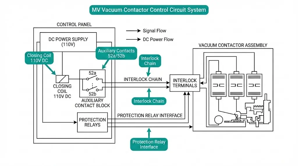
Every MV contactor control circuit builds from the same foundational elements. Understanding their function and ratings prevents specification errors that surface during commissioning—or worse, during operation.
Closing Coil Types
The closing coil energizes an electromagnetic actuator that drives moving contacts into the closed position. Two categories dominate:
DC Closing Coils (24, 48, 110, or 220 V DC) suit substation applications where battery backup is essential. These coils exhibit high inrush current—8 to 12 times the sealed holding current—with response times typically between 30 and 60 ms from energization to full close.
AC Closing Coils (110 or 220 V AC) appear commonly in industrial motor control centers. Coil impedance moderates inrush, and power supply requirements remain simpler, though no inherent battery backup capability exists.
The vacuum interrupter assembly requires a closing force of 150–300 N to achieve proper contact pressure. Control coils must deliver sufficient electromagnetic pull-in capability; inadequate closing force causes contact bounce exceeding 2 ms, accelerating erosion and reducing device lifespan.
Opening Mechanisms
Spring-return designs dominate general-purpose applications. A compressed spring opens the contactor when the closing coil de-energizes—no separate trip coil required. Dedicated trip coils provide faster, more forceful opening for critical motor protection where fault clearing speed matters.
Auxiliary Contacts
Position feedback and control logic depend on auxiliary contacts following IEEE/IEC conventions:
Typical ratings reach 5 A at 250 V AC or 30 V DC. Most applications require minimum 2NO + 2NC; complex protection schemes demand 4NO + 4NC or more.
External Interlock Inputs
Control circuits must accept signals from door position switches, upstream breaker auxiliary contacts, protection relay outputs (thermal overload, lockout, overcurrent), and temperature sensors. These inputs prevent unsafe operations before they occur.

Control circuit reliability depends fundamentally on auxiliary power supply configuration. DC supplies at 110 V or 220 V dominate critical applications because they eliminate half-wave rectification delays and provide consistent coil magnetic force independent of supply waveform.
According to IEC 62271-106, the control circuit must maintain reliable operation when auxiliary voltage varies between 85% and 110% of rated value. This tolerance ensures consistent pickup and dropout characteristics during voltage fluctuations common in heavy industrial environments.
The control circuit power consumption varies significantly between holding and pickup states. Pickup current for typical 12 kV vacuum contactor coils ranges from 3 A to 8 A at rated voltage, while holding current drops to 0.5 A to 1.5 A after the armature seats. This 4:1 to 8:1 reduction occurs because the magnetic circuit air gap decreases from approximately 15 mm to < 0.5 mm after closure.
Power supply redundancy matters in vacuum contactor applications. Single-supply architectures risk complete control loss during auxiliary power failures. Dual-supply configurations with automatic transfer switching provide operational continuity—field observations across petrochemical facilities showed dual-supply systems reduced unplanned outages by approximately 35% over 24-month periods compared to single-supply installations.
Modern economizer circuits reduce holding current to 15–25% of pickup current after initial closure, minimizing coil heating in continuous-duty applications such as capacitor bank switching. Dropout voltage thresholds remain above 35% of rated voltage per IEC standards.
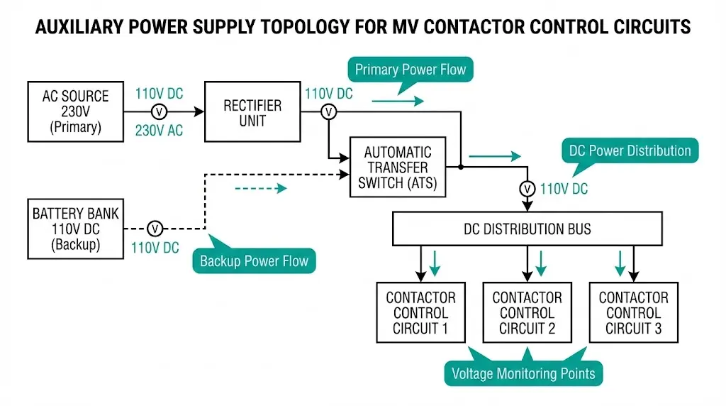
[Expert Insight: Auxiliary Supply Sizing]
- Battery banks must deliver sufficient instantaneous current for simultaneous multi-contactor operations without voltage collapse below 85%
- Size DC bus capacity for worst-case scenario: all contactors closing within 100 ms during automatic transfer sequences
- Include 20% margin above calculated maximum demand for aging battery capacity
- Monitor DC bus voltage continuously; alarm at 90% to allow corrective action before dropout threshold
The fundamental closing circuit represents the simplest viable control scheme for MV vacuum contactors with DC closing coil and spring-return opening.
Circuit Topology
+110V DC ─── [F1: Fuse 6A] ─── [S1: Close PB] ──┬── [52b] ─── [CC: Closing Coil] ─── -110V DC
                                                │
                                           [52a seal-in]
An NC open pushbutton (S2) in series breaks the seal-in path when pressed.
Operating Sequence
Fuse Sizing for Inrush
Control fuse selection must accommodate closing coil inrush. For a 110 V DC coil with 2 A sealed current and 20 A inrush, a 6 A slow-blow fuse provides adequate protection without nuisance operation. Fast-acting fuses will blow on every closing attempt.
Motor control and capacitor switching applications require integration with external protection relays. Adding lockout and thermal relay contacts to the basic circuit enables automated fault response.
Circuit Modification
Series NC contacts extend the control path:
[Close PB] ─── [52b] ─── [86-NC: Lockout] ─── [49-NC: Thermal] ─── [CC]
Trip Sequence
When the lockout relay (86) picks up due to a severe fault, its NC contact opens immediately, breaking the control circuit. The contactor opens via spring return. Manual reset of the lockout relay is required before any reclose attempt—this prevents automatic reclosing onto a faulted circuit.
Thermal overload relays (49) operate similarly but may include auto-reset options for non-critical applications. The NC contact opens on motor over-temperature, tripping the contactor without operator intervention.
Field Reliability Considerations
Relay contact resistance degrades in dusty or humid environments. Gold-flashed contacts or sealed relay housings improve long-term reliability. Maintenance intervals should include contact inspection every 12–24 months, with cleaning or replacement as surface condition dictates.
For deeper understanding of the vacuum interrupter technology enabling these switching operations, the core arc extinction principles apply directly to contactor performance under fault conditions.
Capacitor bank energization imposes severe inrush stresses. Back-to-back switching of capacitor banks can produce inrush currents exceeding 100 times rated current with frequencies reaching several kHz. A two-stage closing sequence limits this stress.
Two-Contactor Scheme
Control Logic
K1 Control: [Close PB] ─── [Permissive] ─── [K1-52b] ─── [K1 Closing Coil]

K2 Control: [K1-52a] ─── [Timer T1: 50-100ms] ─── [K2 Closing Coil]
The K1-52a contact in K2’s control path provides critical interlock: K2 cannot close unless K1 has fully closed. If K1 fails mid-stroke, K2 remains open, preventing uncontrolled inrush.
Timing Considerations
Timer accuracy directly affects system performance. A delay too short (under 30 ms) allows excessive inrush before resistance insertion takes effect. A delay too long (over 150 ms) overheats the resistor—these components are sized for transient duty, not continuous current.
Resistor sizing depends on capacitor bank kVAR, system voltage, and utility or plant inrush limits.

[Expert Insight: Capacitor Switching Field Observations]
- Pre-insertion resistor failures often trace to timer drift—verify timing accuracy during annual maintenance
- Contact welding on K1 indicates resistor undersizing or timer set too long
- Monitor K2 auxiliary contact timing relative to K1; mechanical wear increases sequence delay over years
- Replace pre-insertion resistors proactively at 50,000 operations or 10 years, whichever comes first
Reversing starters use two contactors—Forward (KF) and Reverse (KR)—with mandatory interlocks preventing simultaneous closure. Without interlocks, both contactors closing creates a dead short across motor windings.
Electrical Interlock Logic
Each contactor’s close circuit includes the other contactor’s NC auxiliary:
KF Control: [Fwd PB] ─── [KF-52b] ─── [KR-52b] ─── [KF Coil]
KR Control: [Rev PB] ─── [KR-52b] ─── [KF-52b] ─── [KR Coil]
When KF closes, its 52b contact (NC type, which opens when KF closes) breaks KR’s control circuit. The reverse contactor cannot energize while forward remains closed. The logic works identically in reverse.
Mechanical Interlock Requirements
Physical blocking bars provide secondary protection and are required by installation codes for reversing applications. Mechanical interlocks operate independently of electrical systems—they function even with control circuit failures.
Common OEM Errors
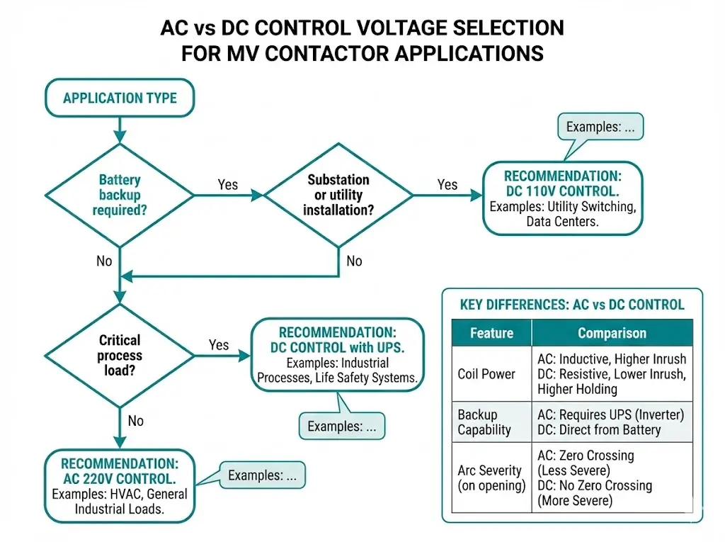
Control voltage selection affects system architecture, backup capability, and maintenance requirements. Neither option universally outperforms the other—application specifics determine the better choice.
| Factor | AC Control (110/220 V AC) | DC Control (24/110/220 V DC) |
|---|---|---|
| Coil holding power | Higher continuous draw | Lower, no reactive component |
| Battery backup | Requires UPS/inverter | Direct battery connection |
| Contact arc on breaking | More severe | Less severe, easier extinction |
| Inrush behavior | Moderate, impedance-limited | High inrush, fast decay |
| Typical applications | Industrial motor starters | Substations, critical loads |
Application Guidance
Substation installations favor DC control because station batteries provide direct backup during AC supply failures—critical for fault clearing when utility power is lost. The contactor must open to isolate faults regardless of auxiliary AC availability.
Industrial plants often prefer AC control for simplicity and lower installed cost. Motor control centers typically include AC auxiliary buses, and battery systems add complexity that many facilities prefer to avoid.
For critical process loads in industrial settings, DC control with dedicated battery backup provides the reliability of substation practice without full substation infrastructure. Understanding vacuum circuit breaker ratings helps specify appropriate voltage and current parameters that apply equally to contactor selection.
Proper wiring practices prevent the intermittent failures and nuisance trips that plague poorly executed installations. These specifications reflect field experience across hundreds of MV contactor deployments.
Control Cable Specifications
Use stranded copper conductors, minimum 1.5 mm² (16 AWG) for DC control circuits up to 10 A. Solid conductors break under vibration and thermal cycling. Shielded cables are required where control wiring runs parallel to power conductors exceeding 50 m—induced noise causes erratic operation.
Calculate voltage drop for long control runs. A 100 m run of 1.5 mm² cable carrying 5 A drops approximately 6 V at DC. If this drop pushes auxiliary voltage below 85% of rated during inrush, upsize conductors or reduce run length.
Terminal and Connection Quality
Use crimped ring terminals with calibrated tooling—hand-crimped connections fail. Apply torque specifications per terminal block manufacturer, typically 0.5–1.2 Nm for standard control terminals. Loose connections cause resistance heating and intermittent contact.
Separation and Routing
Maintain physical separation between control and power wiring per local electrical codes and IEC 61439-1 requirements. Route control wiring away from high-current bus bars to minimize electromagnetic interference. Separation distances of 150–300 mm are typical depending on voltage class and enclosure construction.
Commissioning Verification
Before energization, verify continuity of all control paths, measure insulation resistance (minimum 1 MΩ at 500 V DC), and perform functional tests of each control sequence. Document auxiliary contact timing—this baseline enables future troubleshooting.
Environmental considerations for enclosure design align with guidance in the indoor vs outdoor VCB selection guide, as similar ingress protection and climate factors affect control circuit longevity.
Integrating MV vacuum contactors into switchgear assemblies demands accurate documentation and responsive technical support. XBRELE provides OEMs with comprehensive resources for control circuit design.
Pre-engineered control circuit documentation accompanies contactor orders, including schematic diagrams, terminal assignments, and auxiliary contact specifications. Standard configurations provide 2NO + 2NC auxiliary contacts; 4NO + 4NC options accommodate complex protection and monitoring requirements.
Technical support extends to custom interlock schemes, PLC integration wiring, and SCADA communication protocols. Application engineers assist with capacitor switching coordination, motor starting sequences, and reversing starter configurations.
Contact XBRELE’s vacuum contactor manufacturer team to request schematic packages and discuss specific integration requirements for your switchgear project.
External Reference: IEC 62271-106 — IEC 62271-106 standard for AC contactors
What control voltage is standard for MV vacuum contactors in substation applications?
110 V DC predominates in substation installations because it connects directly to station battery systems, ensuring contactor operation during AC supply failures critical for fault isolation.
How do I size the control circuit fuse for closing coil inrush?
Select a slow-blow fuse rated at 3–4 times the coil sealed current. For a coil with 2 A holding current and 16–20 A inrush, a 6 A slow-blow fuse typically provides adequate margin without nuisance blowing.
Why does my capacitor bank contactor experience contact welding?
Contact welding usually indicates pre-insertion resistor bypass occurring too early (timer set too short) or resistor undersizing. Verify timer accuracy and resistor thermal capacity against actual inrush magnitude.
Can mechanical interlocks alone protect reversing motor starters?
Mechanical interlocks provide secondary protection but should never serve as the sole interlock method. Electrical interlocks via auxiliary contacts respond faster and provide redundancy against mechanical binding or wear.
What causes intermittent contactor operation that’s difficult to diagnose?
Loose control terminal connections and degraded interlock relay contacts cause most intermittent failures. Thermal cycling loosens connections over time; re-torque all control terminals during annual maintenance.
How many auxiliary contacts should I specify for PLC integration?
Specify minimum 4NO + 4NC for PLC-integrated applications: 2 contacts for status feedback (open/closed), 2 for seal-in and local indication, and reserves for future protection relay inputs or additional monitoring points.
What is the typical lifespan of MV vacuum contactor control components?
Auxiliary contacts and closing coils typically achieve 1–2 million mechanical operations under normal conditions. Electrical life depends on switched current; contacts switching near rated current may require replacement at 100,000–500,000 operations.