Precisa das especificações completas?
Faça o download do nosso Catálogo de Produtos 2025 para obter desenhos detalhados e parâmetros técnicos de todos os componentes do quadro elétrico.
Obter catálogo
Faça o download do nosso Catálogo de Produtos 2025 para obter desenhos detalhados e parâmetros técnicos de todos os componentes do quadro elétrico.
Obter catálogo Faça o download do nosso Catálogo de Produtos 2025 para obter desenhos detalhados e parâmetros técnicos de todos os componentes do quadro elétrico.
Obter catálogo
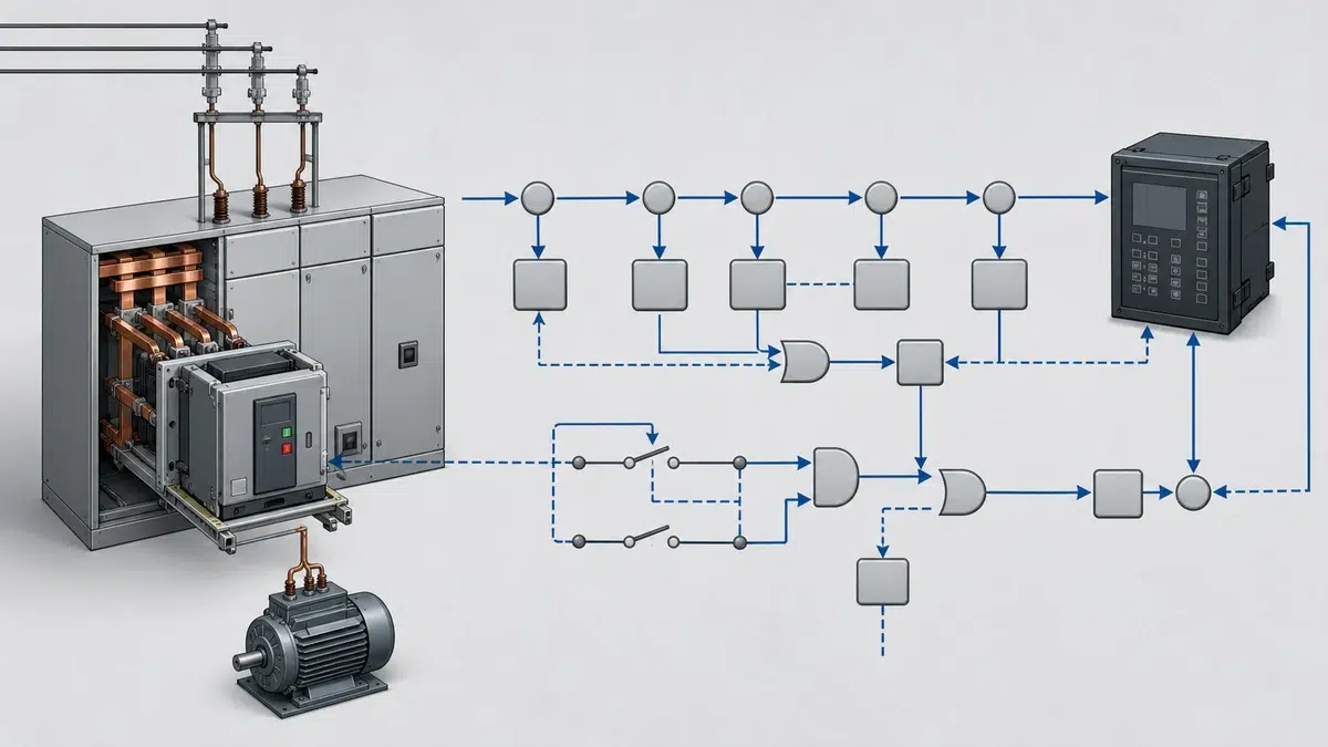
Automatic reclosing has saved countless hours of unnecessary outage time on distribution feeders. A transient fault clears, the breaker recloses, and the system restores itself without anyone touching a switch. That logic works brilliantly on overhead lines where most faults are temporary. It works considerably less well when the load on the other end of the cable is a 500 kW induction motor mid-coast after a trip, and the reclose happens to catch the motor at a point in its residual voltage decay where the phase angle between the line and the machine is 150°. The result can be a mechanical torque spike severe enough to shear a shaft coupling or damage the motor windings before any protection has time to react.
Understanding VCB reclose logic in motor feeder applications is therefore not an academic exercise. It is a practical engineering decision with real consequences for equipment life, personnel safety, and system reliability. This article walks through the principles of auto-reclose, explains why motor loads create unique hazards, identifies the conditions under which auto-reclose must be disabled or blocked, and gives engineers and technicians a structured framework for making that decision correctly.
Auto-reclose originated as a solution to a specific problem: temporary faults on overhead distribution lines. Lightning strikes, wind-blown conductors, bird contacts, and falling branches cause the majority of distribution faults, and a large proportion of those faults are self-clearing once the arc is extinguished. Studies across utilities consistently show that between 70 and 85 percent of overhead line faults are transient. Auto-reclose capitalises on this by commanding the breaker to close again after a dead time, typically somewhere between 0.3 seconds and a few seconds depending on the protection philosophy.
The function works by monitoring protection trip outputs. When a qualifying protection element operates and trips the breaker, the auto-reclose element starts a dead-time timer. At timer expiry, provided that a set of readiness conditions is satisfied, the breaker receives a close command. If the fault has cleared, the system restores normally. If it has not, a second trip occurs and the reclose function either attempts another cycle or locks out, depending on the programmed shot count.
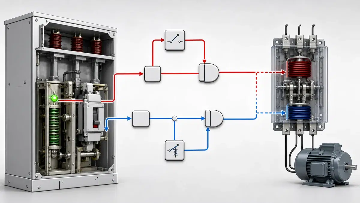
ABB documents that the auto-reclose function can be blocked by selected protection trip signals or a digital input, and that breaker position and status together with a ready-to-close condition are relevant inputs to the sequence. This architecture is important: the blocking mechanism is a first-class feature of the function, not an afterthought. The designers anticipated that not every trip should qualify for reclosing.
Modern numerical protection relays increasingly use explicit application modes to enforce appropriate function sets for different load types. Schneider Electric distinguishes feeder and motor relay application modes in their relay product line: feeder-related functions such as auto-reclose are available in feeder mode, while motor mode provides motor-start supervision and other motor protections, and settings must use the correct application mode for the intended application. The Schneider Electric relay application guidance is the primary source for the product-specific requirement stated here.
This is a significant design choice. The relay manufacturer is essentially codifying the engineering judgment that auto-reclose and motor protection belong to different functional domains. Enabling auto-reclose in a motor application mode would require the engineer to deliberately override a mode boundary, which acts as a forcing function for conscious consideration. When a relay is configured in motor mode, the absence of auto-reclose is not an oversight; it reflects the application engineering.
The practical implication for engineers commissioning VCB panels on motor feeders is that relay configuration starts with mode selection. Choosing feeder mode on a motor feeder simply to access the auto-reclose function is an incorrect application of the relay. The protection coordination required by standards such as IEC/EN 60947-4-1, which Schneider's motor-feeder guidance identifies as requiring coordination between protection and control components as part of motor-feeder design, cannot be achieved when the relay is operating outside its intended mode. Use the vacuum circuit breaker options to screen available equipment against the project duty before requesting a final configuration.
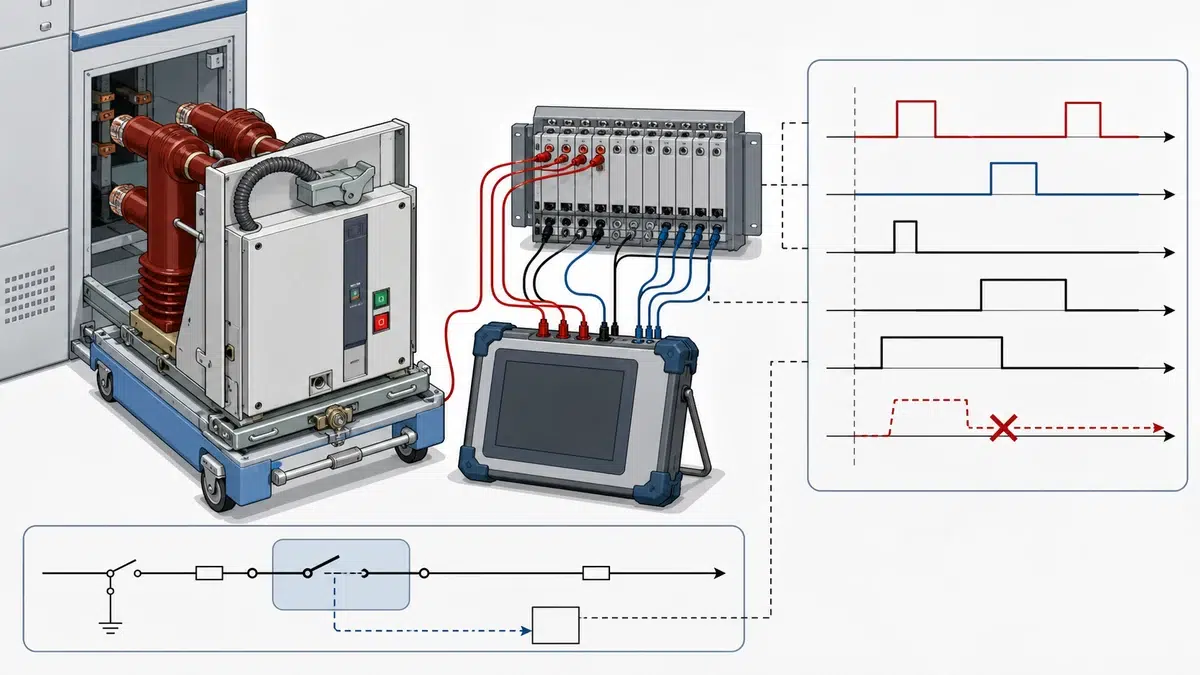
When a running induction motor loses supply, it does not immediately stop producing voltage at its terminals. The motor's rotor flux decays exponentially with a time constant that depends on the machine's electrical design—typically ranging from 0.1 seconds for small motors to well over a second for large, high-inertia machines. During this decay period, the motor acts as a generator, producing a terminal voltage that drifts in both magnitude and phase angle relative to the supply.
The danger arises when the supply is restored before the motor's residual voltage has decayed to a safe level and before the phase angle relationship between the residual voltage and the incoming supply is favourable. If the two voltages are out of phase, the instantaneous voltage difference across the breaker contacts at the moment of closure can be up to twice the nominal voltage. The resulting inrush current can reach multiples of the already-elevated motor starting current, and the electromagnetic torque developed in the motor can spike to values many times the rated full-load torque. For the rated-data check, compare these conditions with the VCB ratings and selection guide.
Mechanical systems are typically sized for starting torque, not for out-of-phase reclosing torque. Shaft couplings, gearboxes, and driven equipment can sustain damage that does not manifest immediately but accumulates over repeated events. Some equipment—pump impellers, compressor pistons, turbine blades—cannot tolerate the shock at all. The motor windings themselves can experience inter-turn insulation stress that shortens service life.
For these reasons, the dead time used in overhead line auto-reclose—often less than one second on distribution systems—is entirely inappropriate for most motor applications. Even a three-second dead time may be insufficient for a large, high-inertia motor.
There is no single universal rule, but engineering practice and relay manufacturer guidance converge on several conditions that individually or in combination mandate that auto-reclose be disabled or blocked.
**The feeder supplies a single large motor.** When the entire feeder load is one motor, there is no diversity benefit from reclosing. The motor will be in a residual voltage decay condition after every trip, regardless of cause. Unless synchronism-check or residual voltage supervision is implemented, reclosing is unsafe.
**The motor drives critical or fragile process equipment.** Pumps in HVAC systems can tolerate occasional shock better than single-screw compressors or centrifuges. When the driven equipment has low mechanical tolerance for torque transients, auto-reclose should be defeated.
**The protection system cannot guarantee fault discrimination.** Auto-reclose on a feeder presupposes that the relay can distinguish between a fault on the feeder cable and a fault inside the motor. A fault inside the motor windings will not clear during the dead time. Reclosing into a winding fault can extend the damage dramatically. If differential protection or other motor-internal fault detection is not available, the risk-benefit balance favours lockout.
**The relay is configured in motor application mode.** As noted above, motor mode in modern numerical relays typically excludes auto-reclose as an available function. If the relay's application mode has been set correctly for the motor application, auto-reclose should not be enabled.
**Process continuity requires controlled restart.** Many industrial processes require a controlled, sequenced restart following a trip. Auto-reclose bypasses the process control system's restart interlock logic, potentially restarting a motor before mechanical conditions are safe for the driven process.
**The electrical system uses unit protection for the motor.** Where the VCB is part of a unit protection scheme including differential elements for the motor, a trip from the differential element must not result in auto-reclose. The differential trip should be configured as a blocking input to the reclose function using the digital input blocking architecture described in ABB's relay documentation.
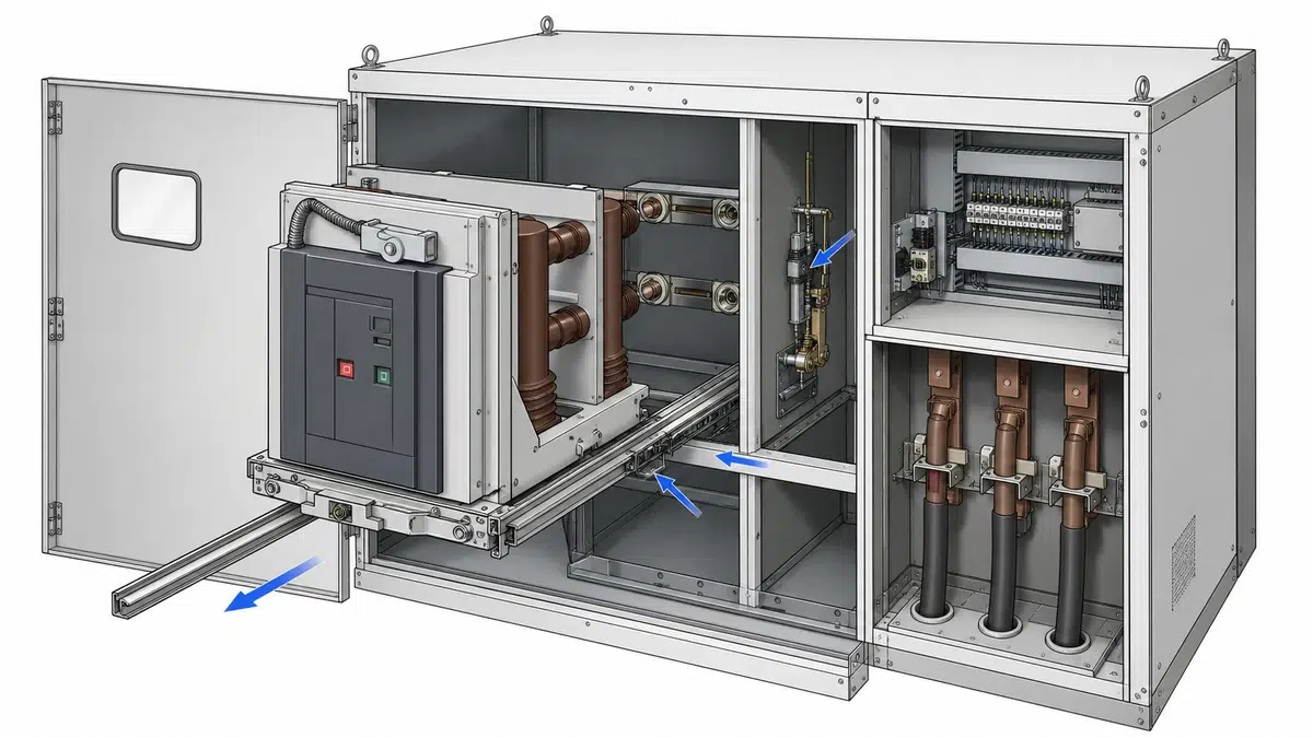
Where a relay is installed in feeder mode but also serves motors on a mixed feeder, selective blocking of auto-reclose for certain trip types is the appropriate engineering solution. The ABB architecture provides a model: the auto-reclose function can be blocked by selected protection trip signals or a digital input.
In practice, this means mapping protection output signals to the reclose blocking input based on which elements should inhibit reclosing. Overcurrent trips from downstream motor faults, earth fault trips from motor frame faults, and thermal overload trips should all feed the blocking logic. Overcurrent trips from upstream faults or feeder cable faults, where the engineer is confident the fault was on the cable rather than the motor, can be allowed to initiate a reclose attempt, subject to residual voltage supervision. Use the breaker closing/opening fault guide to separate control-circuit, coil, interlock, and mechanism causes after a failed operation.
Residual voltage supervision, implemented as an undervoltage check on the load-side busbar voltage transformer, provides an additional safety layer. If load-side voltage has not decayed below a threshold—say 20 to 25 percent of nominal—by the end of the dead time, the close command is inhibited and the reclose function locks out. This is analogous to synchronism-check relaying used in generation applications and provides a direct measurement-based safeguard rather than relying solely on a timer.
The VCB itself must be ready to close reliably when commanded. Breaker position contacts, spring-charged status contacts, and anti-pumping relay status all feed into the ready-to-close condition. If the VCB has failed to charge its closing spring within the permitted window—a scenario covered in detail in troubleshooting guides for closing and opening failures—the reclose sequence must abort rather than issue a close command that will not be executed.
Commissioning a VCB on a motor feeder requires explicit verification that reclose logic is correctly configured. The following checks should form part of the factory acceptance test and site acceptance test documentation. The breaker FAT/SAT verification guide provides a companion structure for acceptance criteria, results, and closeout records.
First, confirm the relay application mode. For a dedicated motor feeder, the relay should be in motor mode, and the auto-reclose function should be absent or suppressed. If the relay is in feeder mode for any reason, confirm that blocking inputs are correctly mapped.
Second, inject test current through each protection element that should block reclose and verify that the blocking signal reaches the reclose function and inhibits a close command. This test must be performed element by element.
Third, verify dead-time settings. If auto-reclose is permitted on any trip element, confirm that the dead time is sufficient for the motor's residual voltage to decay. For motors above about 150 kW, a minimum dead time of five to ten seconds is commonly applied; for very large machines, longer times or residual voltage supervision are required.
Fourth, verify the breaker readiness check. With the VCB open and the spring discharged, confirm that a reclose command is inhibited until the spring is recharged and the ready-to-close condition is satisfied.
Fifth, test lockout behaviour. After the maximum programmed reclose shots, confirm that the reclose function locks out and that a manual reset is required, preventing further automatic close commands.
The primary reason is the risk of out-of-phase reclosing onto a motor that is still producing residual voltage. When a running motor trips, its rotor flux decays gradually, and the terminal voltage drifts in phase relative to the supply. If the VCB recloses before the residual voltage has decayed to a safe level, the voltage difference across the contacts at the moment of closure can drive inrush currents and torque spikes that damage motor windings, shaft couplings, and driven equipment. Unlike overhead line faults, which are commonly transient and self-clearing, motor faults or supply interruptions do not benefit from the same logic that justifies auto-reclose on distribution feeders.
Relay application mode is a configuration-level mechanism that determines which protection and control functions are available. Schneider Electric's relay products, for example, separate feeder mode—which includes auto-reclose—from motor mode, which provides motor-start supervision and motor-specific protections. Setting a relay to motor mode for a motor feeder application therefore structurally excludes auto-reclose from the available function set. This is not a limitation but a design feature that enforces correct application engineering. Engineers should not bypass this by selecting feeder mode solely to access auto-reclose on a motor feeder, as this would compromise the overall protection coordination required by IEC/EN 60947-4-1.
A blocking input is a signal path that, when activated, prevents the auto-reclose function from issuing a close command regardless of whether the dead time has expired or the breaker is otherwise ready to close. ABB's relay architecture explicitly includes this blocking capability, allowing selected protection trip signals or external digital inputs to inhibit reclosing. In motor feeder applications, this mechanism is used to ensure that trips originating from motor differential protection, thermal overload elements, or earth fault elements do not initiate a reclose cycle. The engineer selects which trip signals qualify for reclosing and which mandate lockout, implementing the distinction through the relay's blocking input mapping.
Residual voltage supervision is a measurement-based interlock that monitors the voltage on the load side of the VCB after a trip. If the motor's decaying terminal voltage has not fallen below a defined threshold—typically 20 to 25 percent of nominal rated voltage—at the end of the dead time, the auto-reclose function is inhibited and the reclose cycle locks out rather than proceeding. This provides a direct physical measurement of the motor's state rather than relying solely on a fixed dead-time timer. It is particularly important for large, high-inertia motors that may sustain significant residual voltage for several seconds after disconnection, and it is analogous to synchronism-check relaying used in generator applications.
The correct commissioning approach involves several discrete verification steps that should be documented in both factory and site acceptance test records. Engineers must first confirm the relay application mode and verify that auto-reclose is absent or correctly suppressed. For relays in feeder mode, each protection element that should block reclose must be individually tested by injecting test current and confirming that the blocking signal reaches and inhibits the reclose function. Dead-time settings must be confirmed as adequate for the motor size, with longer times or residual voltage supervision applied for larger machines. The breaker readiness check must be tested with the spring discharged to confirm close commands are inhibited. Finally, lockout behaviour after the maximum shot count must be verified to ensure that manual reset is required before any further automatic close attempts.