Precisa das especificações completas?
Faça o download do nosso Catálogo de Produtos 2025 para obter desenhos detalhados e parâmetros técnicos de todos os componentes do quadro elétrico.
Obter catálogo
Faça o download do nosso Catálogo de Produtos 2025 para obter desenhos detalhados e parâmetros técnicos de todos os componentes do quadro elétrico.
Obter catálogo Faça o download do nosso Catálogo de Produtos 2025 para obter desenhos detalhados e parâmetros técnicos de todos os componentes do quadro elétrico.
Obter catálogo
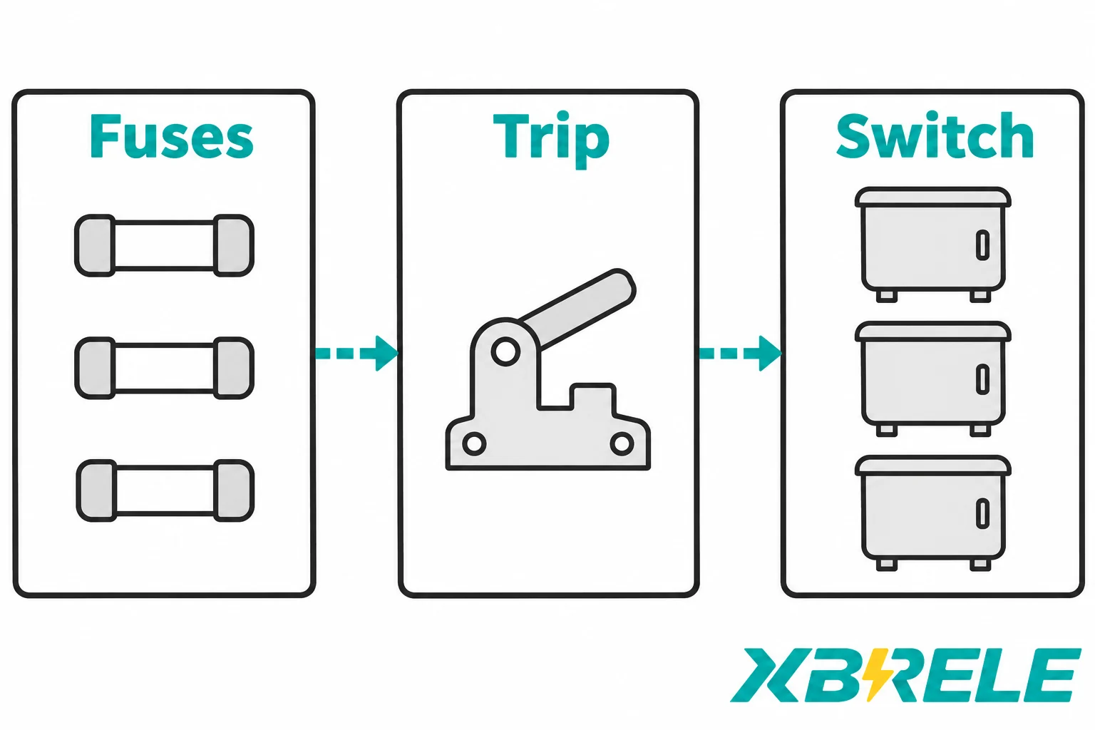
Understand transfer current in MV transformer switch-fuse combinations and the fuse, striker, enclosure and protection checks needed for a coordinated proposal.
A medium-voltage transformer feeder is often protected by a load-break switch with a current-limiting fuse in each phase. The fuse is the fast, current-limiting element that limits and interrupts high fault currents within its declared capability; the switch is the device that makes and breaks normal load current, provides isolation where it has the specified disconnector function, and — in a coordinated combination — finishes the interruption when the fault is too small for the fuse to clear on its own. Neither device is a spare part for the other. They are a matched pair, and the number that describes how they hand work to each other is the transfer current.
That number cannot be read off the transformer nameplate. It is a property of one specific fuse type fitted in one specific switch, and it sits inside a declared rating for that combination. Getting a usable fuse proposal therefore means giving a supplier the transformer duty, the source strength, the enclosure conditions and the downstream protection — and receiving back not just an ampere rating but the combination identity, the fuse characteristics and the declared transfer basis.
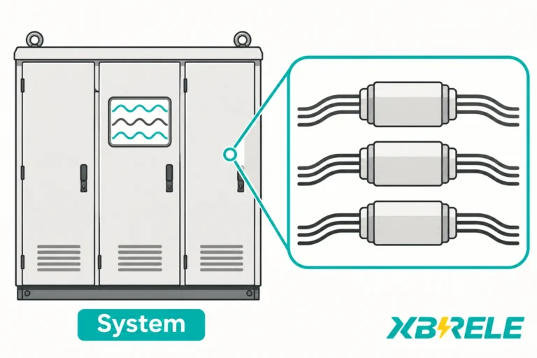
Physically, the arrangement is simple to describe. Three poles, three current paths. In each path a fuse cartridge sits in series with a set of switch contacts, and the three paths are separate circuits that happen to share one operating mechanism and one enclosure.
What makes it a combination rather than three independent circuits plus a switch is the striker. A fuse selected for striker-operated coordination includes a compatible striker. Fuse operation releases the striker through its designed mechanism; the construction and triggering behavior must come from the actual fuse documentation. The pin strikes a lever or trip bar on the switch, and the switch is released. Because the release acts on the common mechanism, any one fuse operating trips all three poles — not just the faulted phase.
That mechanical link runs in one direction only. The fuse can trip the switch; the switch cannot make the fuse operate. This is worth stating because engineers new to the arrangement sometimes expect bidirectional coordination, or expect the switch to be able to “help” the fuse on every fault.
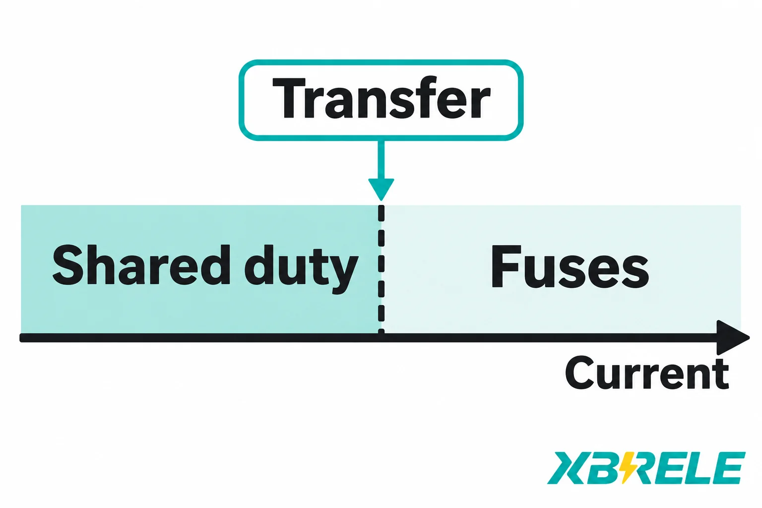
The duty split is what the combination is for:
This is also the point where the standard structure matters. IEC 62271-105:2021, in its third edition, addresses three-pole functional combinations of switches or switch-disconnectors with current-limiting fuses, for voltages above 1 kV up to 52 kV, designed for declared making and breaking duties; it replaced the 2012 edition. The fuse itself is covered by its own standard: IEC 60282-1:2020 concerns indoor and outdoor high-voltage current-limiting fuses for AC 50/60 Hz systems above 1000 V. Passing a fuse standard does not describe how that fuse behaves inside a particular switch, which is why combination coordination needs the switch-fuse requirements as a separate layer.
One scope boundary is worth drawing early. A switch-fuse combination is not a fuse-contactor combination. Fuse-contactor (F-C) equipment commonly serves motor starting duty, where the contactor is built for frequent operations and the fuse handles short-circuit current; its interlocks, duty class and coordination logic belong to a different apparatus context. This article addresses a transformer feeder using a load-break switch or switch-disconnector with fuses. The selected apparatus must provide the required switching and isolation functions; those duties cannot be inferred from a generic single-line symbol. The two arrangements look superficially similar in a single-line diagram and behave quite differently in practice.
The transfer-current definition in IEC 62271-105:2021, 3.7.108 concerns striker operation: the three-phase symmetrical current at which the fuse and the switch exchange their breaking duties. The value is associated with the striker acting, because the striker is what starts the switch on its way.
The behaviour either side of that value is asymmetric:
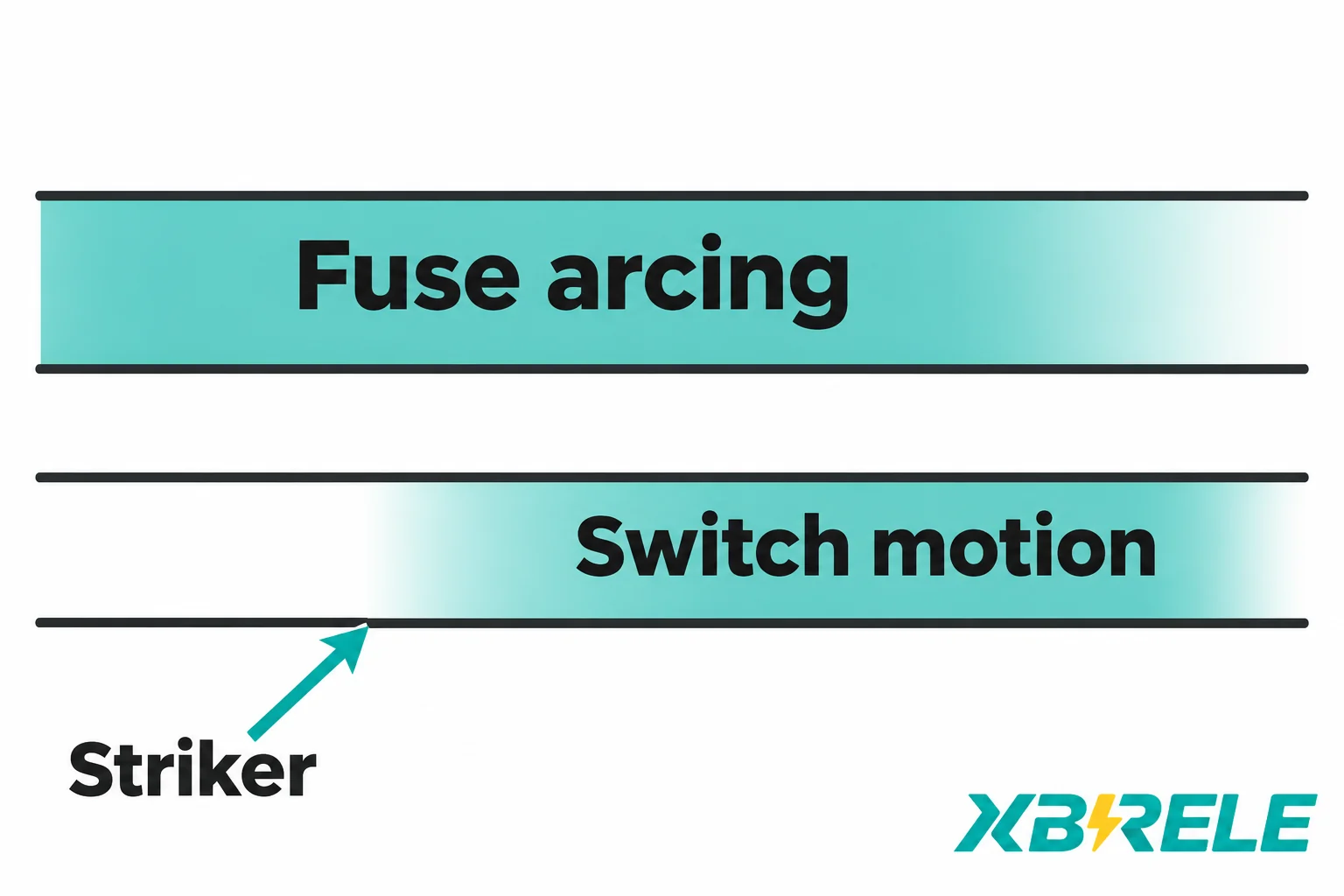
That last term has a precise meaning: it runs from the moment fuse arcing commences to the moment the switch arcing contacts are separated in all poles. It is not “how long the fuse takes to blow” in the colloquial sense, and it is not a fixed constant across products.
The most common misreading of this behaviour concerns the striker. The ABB fuse guide, sections 4.4 and 4.6, explains that striker actuation can occur antes fuse interruption is complete. Arcing inside a current-limiting fuse can still be in progress while the pin has already travelled and the switch mechanism has begun to move. So it is wrong to conclude that when the switch starts to open, the other two circuits are already dead. The switch may be moving into an already-clearing circuit, and that is precisely the situation the transfer definition is written to describe.
Two practical consequences follow.
First, transfer current is a property of a specific fuse-switch pair with specific timing, not of the fuse’s rated current and not of the highest fault level at the installation. A declared maximum prospective fault current alone does not check the lower fault-current range or the exchange region for the particular fuse and switch.
Second, the declared value must be compared on the same basis as the calculated or actual value you are checking. A rated transfer capability for a combination is meaningful only in the context of the fuse type, the switch type and the conditions under which it was declared. Comparing a site-specific calculation produced on one set of assumptions against a catalogue figure produced on different assumptions — different voltage, different fuse reference, different definition of the exchange point — is a common source of false confidence. There is no universal timing equation and no fixed multiplier that converts a transformer rating into a transfer current; the review uses the fuse’s actual time-current characteristics and the switch’s fuse-initiated opening behaviour.
Transformer feeder studies go wrong most often when two of these five quantities are treated as one. They answer different questions and come from different documents.
| Quantidade | What it describes | Belongs to | Question it answers |
|---|---|---|---|
| Fuse rated current (Ir) | The current the fuse is designed to carry continuously under stated service and thermal conditions | The fuse, at its rated voltage and mounting conditions | Will this fuse survive normal load, including permissible overload and enclosure derating? |
| Minimum breaking current (I3) | The lowest current a back-up fuse can interrupt on its own, under prescribed voltage and test conditions | The fuse capability | Below what current must something else complete the interruption? |
| Actual transfer current | The three-phase symmetrical current at which this fuse and this switch exchange breaking duties on the project’s own basis | The specific combination, assessed for the project | Where is the boundary on this feeder, with this fuse and this switch? |
| Rated transfer current (capability) | The declared transfer value for an approved combination under stated conditions | The combination, as declared | Does the arrangement stay inside what was demonstrated for it? |
| Take-over current | The intersection coordinate of two protective-device time-current curves, at which their declared operating times coincide | The pair of protective devices being coordinated | Which device operates first at a given current — for example the fuse and the complete relay-operated switch clearing characteristic? |
The persistent error is to label the intersection of a fuse curve and another curve “the transfer current.” A take-over current is a coordination coordinate read from published curves; it says which device wins a race. Striker transfer is a mechanical-electrical exchange inside a switch-fuse assembly, and depends on the switch’s opening time after the striker fires, not only on curve crossing. The two can be numerically close on some systems and far apart on others. They are not the same quantity and should not be used interchangeably in a protection study.
Equally, no single threshold resolves the whole study. A complete check covers:
The starting point is a reference current, not a selection multiplier. For a transformer of rated power S at rated voltage U, the rated current is In = S / (√3 × U). That number tells you the order of magnitude of the current the feeder will normally carry. It does not tell you the fuse ampere rating, and treating it as though it did is the most common shortcut that fails later.
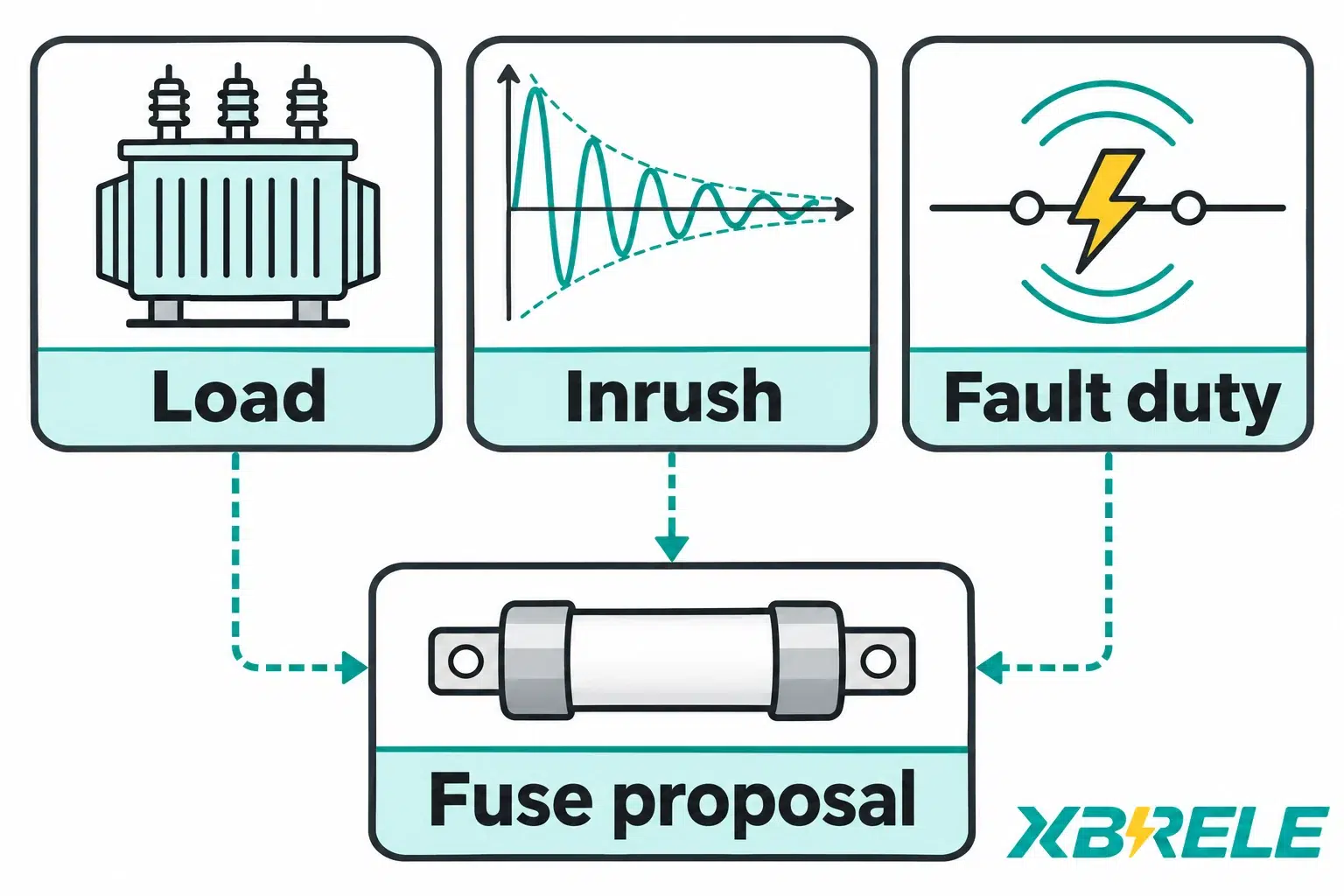
Four families of input actually decide the selection.
Transformer identity and capability. Rated power, voltage ratio, vector group, tapping range, impedance voltage, cooling class and ambient rating. Taps matter because a fuse chosen for the nominal tap may be marginal at the extreme tap. Impedance is needed for the through-fault calculation. Obtain inrush characteristics separately rather than deriving them from the nameplate impedance alone.
Intended load and overload. Continuous demand, permissible cyclic overload, planned future load, and the ambient temperature inside the enclosure rather than in the room. The fuse’s rated current applies under stated thermal conditions; the permissible carrying capability can differ between a warm enclosure and an open mounting.
Magnetising inrush. Energising a transformer draws a decaying asymmetric current with a high first peak. Its shape and magnitude depend on the transformer design, the point on the voltage wave at closing, and the source impedance. The correct basis is the transformer manufacturer’s inrush data or the fuse manufacturer’s documented selection basis for that transformer type — not a remembered rule of thumb.
Fault duty and downstream coordination. The minimum and maximum HV fault currents at the feeder, the secondary fault current referred to the HV side through the transformer ratio and connection, the LV protective device curves, and the transformer damage curve where one is available.
Two of these deserve more than a sentence.
Why upsizing is risky. If a fuse operates on transformer inrush, the reflex is to take the next size up. That changes the whole study. Within a given fuse family, a higher current rating typically moves the time-current characteristic toward higher current or longer operating time; compare the actual candidate curves. The change may delay protection for genuine LV and transformer faults, leave part of the transformer damage curve unprotected, alter coordination with the LV device, or shift the current at which duties are exchanged between fuse and switch. The proposed fuse’s transfer behaviour must be assessed in the specific combination. Upsizing is not a field fix; it is a selection change that must be re-reviewed against the same inputs.
Why a weak source matters. On a feeder with high source impedance, the fault current at the transformer terminals may be modest. If the available fault current falls below the fuse’s minimum breaking current for back-up duty, the fuse cannot be relied on to interrupt alone — back-up fuses have a minimum breaking current and require coordinated interruption below that capability. That is exactly where the switch’s own breaking capability, or an upstream device, becomes part of the functional chain rather than a formality. A design that was fine on a stiff bus can be marginal on a long cable or a small generator-backed source.
Fuse selection produces a candidate. The combination check decides whether that candidate may actually be fitted, and it is the step most often skipped when a replacement fuse is sourced locally.
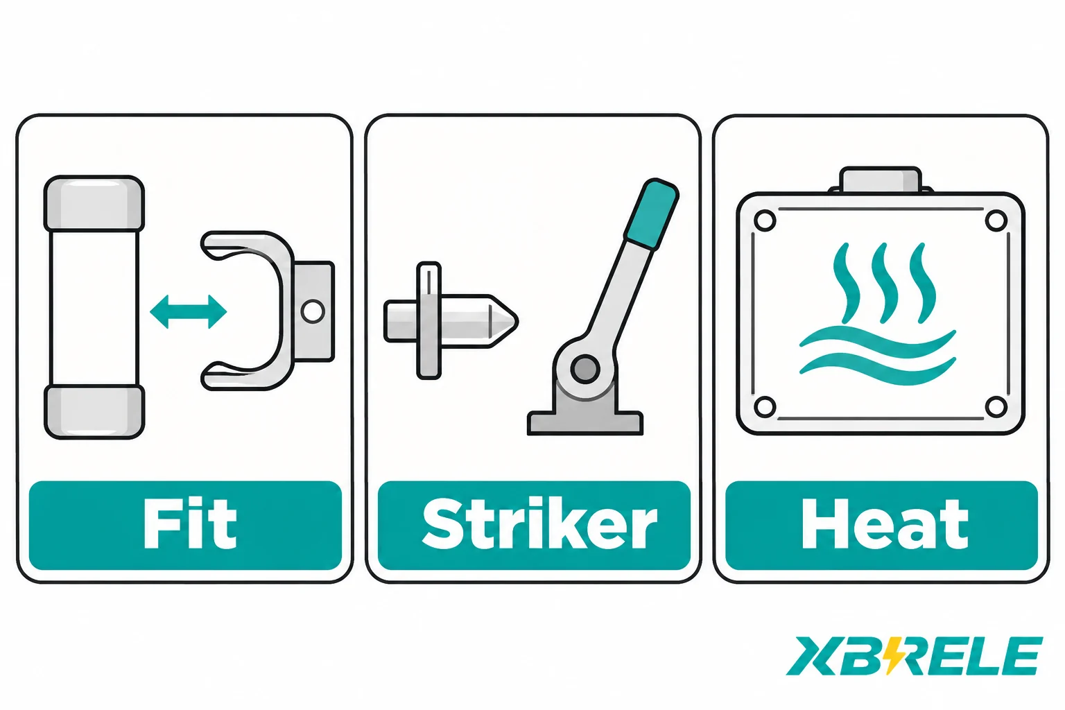
Ask for the document that names approved fuses for the specific switch, by make, type designation, rated current and rated voltage. Not a family name, not a voltage class — the exact reference. A switch that accepts current-limiting fuses is not thereby approved for every current-limiting fuse that fits.
Physical and thermal fit. Cartridge length and diameter, contact style at each end, and the power dissipated by the fuse inside the enclosure. A fuse with a different power loss changes the temperature rise of the compartment, which affects both the switch and the fuse itself. The enclosure’s thermal behaviour is part of the combination, not an installation detail.
Striker interface. Orientation, travel, and the energy the striker delivers to the tripping lever. These must match the switch’s actual drawings. A striker of the right length pointing the wrong way, or with insufficient travel to release the latch, is a fuse that will rupture without tripping the switch — which can defeat the intended all-pole trip.
Trip behaviour and indication. Confirm from documents, not assumption, that striker operation releases all three poles and that the auxiliary contacts and mechanical indicators report the trip state in the way the protection scheme expects.
The declared combination report and its boundaries. Request the report covering this switch and this fuse under the conditions of the project, and read its scope: voltage, current, fuse reference, mounting. Values outside that scope are extrapolation.
Two fuses of the same length and the same ampere rating are not interchangeable. They can differ in element design, striker energy and power loss, and only one of them may appear on the approved list for the switch they are going into. Confirm the reference list rather than assuming interchangeability from the outer envelope.
A proposal is only usable if it lets you close the study without going back for missing data. The table below is the exchange to run. The left column is what you send, the middle is what you should receive, and the right is what makes the reply auditable.
| What you provide | What the proposal should contain | Evidence that makes it usable |
|---|---|---|
| Transformer rating, voltages, vector group, taps, impedance, cooling and ambient class | Proposed fuse make, type, Ir and Ur, with the load and thermal margin shown | Fuse data sheet and the selection basis applied, including enclosure temperature assumption |
| Source data: prospective fault current minimum and maximum at the feeder | Statement of where the feeder sits relative to minimum breaking current and transfer | Fuse time-current curves with tolerance bands, I3 value, clearing I²t and cut-off where relevant to downstream withstand |
| Transformer inrush data, or the design basis if the manufacturer’s data is not yet available | Confirmation that the fuse withstands the stated inrush envelope | The comparison actually performed, not a rule-of-thumb statement |
| Switch identity: exact model and, where relevant, the current catalogue reference | Switch fuse-initiated opening behaviour and the declared transfer value for this combination | Combination report or declaration with its stated scope and conditions |
| LV protective device types and settings, plus transformer damage curve if available | Coordination outcome and any residual gap, especially in the low-overcurrent band | Overlaid curves or a selectivity statement identifying which device operates where |
| Enclosure type, compartment dimensions and expected internal ambient | Fit and thermal confirmation for the proposed fuse in that compartment | Approved fuse reference list for the switch, plus striker interface confirmation against drawings |
Two conditional cases show why the transformer alone cannot drive the answer.
Case A — same kVA, changed source. A 1000 kVA, 11 kV cast-resin transformer is fed from a stiff busbar in one project and from a long cable with a limited upstream transformer in another. The transformer is identical, so a kVA-based table would give the same fuse in both. But the minimum prospective fault current in the second case may sit low enough that the low-overcurrent regime — below the fuse’s minimum breaking current — becomes the governing design condition rather than a footnote. The proposal changes: the switch’s breaking capability and the upstream protection settings now carry part of the duty, and the transfer review has a different current band to examine.
Case B — same kVA, changed enclosure and inrush. The same transformer moved into a small sealed compartment in a hot location raises the internal ambient, reducing the current the fuse can carry continuously. If a replacement transformer of the same kVA also has a higher inrush envelope, the margin between acceptable carrying current and acceptable inrush withstand narrows from both sides. The right response is rarely “one size up”; it is a re-check of load margin, thermal derating, inrush basis and the effect of any rating change on protection speed and transfer.
Request a proposal that matches the defined duty and identifies the supporting documents. XBRELE’s current catalogue lists the FLN36-12 SF6 load-break switch and related switching components, with fuse-selection enquiries handled through the product page; no approved fuse reference list, combination transfer-current report or verified transformer rating table is reproduced here, so those have to be requested for each proposed combination. The FLN36-12 SF6 load-break switch page is the right starting point for a switch-specific enquiry, and the wider peças para comutadores section gives the component context around it.
To move from this article to a usable proposal, assemble four things before contacting anyone: the transformer data sheet, the source fault levels (minimum and maximum), the LV protection schedule, and the enclosure description. Send those together with the switch model through the contact page and ask specifically for the approved fuse reference list, the fuse curves with tolerances, the declared transfer value for the combination and its scope. A reply that contains all four can be checked against the study directly. A reply that contains only an ampere rating cannot.
No. For a three-phase transformer, rated kVA divided by the product of √3 and line-to-line kV gives the rated HV current in amperes, and that is where the arithmetic ends. The fuse ampere rating has to satisfy continuous load including permissible overload at the actual enclosure temperature, withstand the transformer’s magnetising inrush on the manufacturer’s data or a documented selection basis, and still provide the required fault protection with acceptable coordination against the LV device. Those three requirements pull in different directions, and the final rating is the one that satisfies all of them for the specific transformer, source and enclosure — not a value derived from kVA alone.
No, and confusing them misdirects the study. Minimum breaking current is a capability of the fuse alone: the lowest current it can interrupt under prescribed conditions, below which a back-up arrangement must provide coordinated interruption. Transfer current describes the exchange of breaking duties between the fuse and the switch in a specific combination, where above it the fuses clear all three phases and immediately below it the first phase is cleared by a fuse while the remaining phases may be cleared by the switch or by fuses. One is a fuse property; the other is a property of the matched pair and its timing.
Not safely. The approved fuse reference list for the specific switch names fuses by make, type, rated current and rated voltage. Two cartridges that look identical from outside can differ in element design, power dissipation and striker energy, and a striker that does not deliver the right travel or force to the tripping lever will leave the switch closed after the fuse has operated. Physical fit is necessary but not sufficient; the striker interface and the thermal effect inside the enclosure have to be confirmed against the switch drawings and the declared combination.
No. The switch is released by the striker, and the striker can actuate while the fuse is still interrupting. The switch may therefore begin moving and part its contacts while current is still flowing in the circuits it is opening, which is exactly why the duty is described as shared below the transfer current and why the fuse-initiated opening time — measured from fuse arcing commencement to full separation of the switch arcing contacts — is part of the combination’s declared behaviour rather than a detail of the fuse alone.
Only after re-running the selection. A higher fuse rating may solve an inrush-related operation. Within a given family it typically moves the time-current characteristic toward higher current or longer operating time, but the actual candidate curves govern. The change may delay fault protection, leave part of the transformer damage curve uncovered, change coordination with the LV device, or alter the current at which duties are exchanged inside that particular combination. If the nuisance operation is caused by undersized load margin at the actual enclosure temperature or by a transformer inrush that was never documented, the correct fix is to correct the input, not to move up a rating step and hope the rest of the study still holds.