Need Full Specifications?
Download our 2025 Product Catalog for detailed drawings and technical parameters of all switchgear components.
Get CatalogDownload our 2025 Product Catalog for detailed drawings and technical parameters of all switchgear components.
Get CatalogDownload our 2025 Product Catalog for detailed drawings and technical parameters of all switchgear components.
Get Catalog
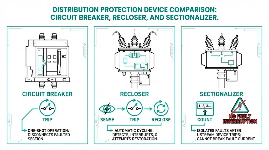
Three devices dominate distribution protection schemes—yet their functional boundaries cause persistent specification errors. Circuit breakers interrupt fault current on command but lack autonomous decision-making. Reclosers sense faults, interrupt current, and automatically restore service. Sectionalizers cannot interrupt fault current at all; they count upstream operations and open only during de-energized intervals. Understanding these distinctions prevents coordination failures, equipment damage, and unnecessary procurement delays across medium-voltage networks.
The recloser vs breaker vs sectionalizer comparison hinges on three questions: Can the device interrupt fault current? Does it sense faults independently? Does it reclose automatically?
Circuit breakers operate as the foundational fault-interrupting device. When fault current exceeds the pickup threshold—typically 400–1,200 A for medium-voltage distribution breakers—protective relays command contact separation. The interrupting mechanism, whether vacuum or SF₆, must extinguish arcs within 3–5 cycles (50–83 ms at 60 Hz). According to IEEE C37.04, circuit breakers are designed for a specific number of fault-current interruptions, generally 10,000 mechanical operations and 30 full-rated fault interruptions before requiring maintenance. Breakers serve as the “last line of defense”—they trip once and require manual or SCADA-initiated reclosing.
Reclosers add automatic fault-clearing intelligence. These devices execute a programmable sequence: trip on fault detection, wait a preset dead time (typically 0.5–2 seconds), then automatically reclose. If the fault persists, the recloser repeats this sequence—commonly 3–4 attempts before locking out. IEC 62271-111 governs recloser performance, requiring interrupting capacity up to 16 kA and operating sequences like 1-fast, 3-delayed. Field experience demonstrates that 70–80% of overhead line faults are transient (tree contact, lightning), making reclosers essential for reducing sustained outages.
Sectionalizers fundamentally differ because they cannot interrupt fault current. Instead, they count upstream protective device operations during fault conditions. After detecting a preset number of upstream trips (typically 1–3 counts), sectionalizers open during the dead time—the zero-current window when the upstream recloser or breaker is open. This coordination requires sectionalizer opening times below 200 ms to complete isolation before reclosing occurs.

This operational hierarchy enables cost-effective protection coordination, with each device optimized for its specific function in the fault-clearing sequence.
[Expert Insight: Field Coordination Realities]
- Sectionalizer count settings must always be at least one count lower than the upstream recloser’s lockout setting (e.g., 2 counts for a 3-shot recloser)
- Dead-time intervals below 500 ms frequently cause sectionalizer misoperation in humid climates where contact mechanisms respond slower
- Mixed-vendor installations require coordination studies accounting for ±10% timing tolerance variations
The core physics separating these three devices determines their application boundaries.
Circuit Breakers: High-Energy Arc Extinction
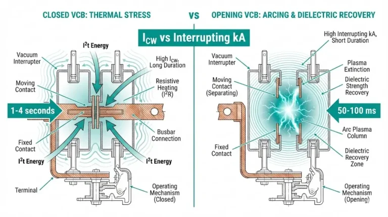
Circuit breakers employ dedicated arc interruption media—vacuum, SF₆, or oil—to extinguish fault current arcs. In vacuum circuit breakers for substation feeders, contacts separate within chambers maintaining pressure below 10⁻⁴ Pa, allowing arc extinction through metal vapor diffusion. Medium-voltage breakers typically interrupt fault currents up to 40 kA at rated voltages of 12–36 kV. According to IEC 62271-100 Section 4.102, circuit breakers must demonstrate specific short-circuit breaking capacity and rated short-time withstand current capabilities. [VERIFY STANDARD: confirm IEC 62271-100 clause 4.102 for breaking capacity requirements]
Reclosers: Integrated Interruption Plus Reclose Logic
Reclosers combine arc interruption hardware with programmable automatic reclose sequences. The device detects overcurrent conditions, trips to interrupt fault current, then automatically recloses after preset time intervals. Modern reclosers utilize vacuum or SF₆ interrupters rated for 12–25 kA interrupting capacity at distribution voltages of 15–38 kV.
Reclosers typically feature interrupting ratings of 8–16 kA at voltages from 15 kV to 38 kV, with contact gaps of 10–20 mm in vacuum interrupter designs.
The critical distinction is embedded control intelligence: reclosers execute up to four trip-reclose cycles before lockout, addressing the majority of distribution faults that are temporary in nature.
Sectionalizers: Zero-Current Switching Only
Sectionalizers represent a fundamentally different design philosophy—they possess no arc interruption capability whatsoever. These devices function as counting switches that open only during zero-current windows created by upstream recloser operations. Because they require no arc-interruption chamber, sectionalizers cost 40–60% less than equivalent-rated reclosers.

When a fault occurs on a distribution feeder, the upstream substation breaker and downstream recloser must operate in sequence without simultaneous tripping. The recloser typically operates first with a fast curve (0.05–0.1 seconds) to clear temporary faults, while the substation breaker serves as backup with time delays of 0.3–0.5 seconds.
According to IEEE Std C37.60, reclosers must coordinate with upstream breakers through time-current characteristic (TCC) separation of at least 0.2 seconds across the entire fault current range. This margin accounts for breaker operating time tolerances of ±10%.
The sectionalizer counts fault current pulses (typically ≥400 A threshold) during recloser operations. After a preset count (usually 1–3 counts), the sectionalizer opens during the dead-time interval between recloser operations—typically 1–2 seconds. This coordinated isolation occurs without the sectionalizer interrupting fault current itself, as its interrupting rating is 0 kA.
Coordination Sequence During a Permanent Fault
Consider a 15 kV distribution feeder with a substation breaker, mid-line recloser, and downstream sectionalizer. When a permanent fault draws 2,500 A:
This sequence ensures minimum outage scope while allowing automatic restoration of healthy feeder sections.
Selecting the right protective device requires systematic evaluation rather than habit-based specification. This framework addresses the most common selection parameters.
Step 1: Evaluate Fault Frequency and Type
Distribution feeders experiencing more than 5 temporary faults per year typically justify automatic recloser installation. Circuits with predominantly permanent faults—such as underground cable networks or indoor industrial facilities—favor circuit breakers paired with dedicated protection relays. Sectionalizers suit radial feeders downstream of reclosers where 80–90% of faults clear during upstream device operations.
Step 2: Assess Interrupting Capacity Requirements
| Device Type | Typical Interrupting Capacity | Application Zone |
|---|---|---|
| Distribution recloser | 8–16 kA symmetrical | Rural/suburban feeders |
| Medium-voltage breaker | 20–50 kA symmetrical | Substations, industrial plants |
| Sectionalizer | 0 kA (no interrupting capability) | Downstream isolation points |
Step 3: Consider Coordination Complexity
For networks requiring coordination among 3+ protective devices, breaker-relay combinations offer superior flexibility through adjustable time-current characteristics. Reclosers provide adequate coordination for simpler radial configurations. For guidance on breaker installation environments, see this VCB selection guide.

Step 4: Verify Total Cost of Ownership
Beyond initial procurement, evaluate maintenance intervals and operational requirements. Reclosers typically require inspection every 3–5 years under normal service conditions, while vacuum circuit breakers may extend to 10-year intervals per IEC 62271-100 maintenance guidelines.
[Expert Insight: Specification Red Flags]
- Never specify a sectionalizer without confirming upstream reclosing capability—this causes catastrophic failures when the device attempts to open under fault current
- Recloser interrupting ratings (8–16 kA) may be insufficient for locations within 2 km of substations where fault currents exceed 20 kA
- Communication protocol mismatches between DNP3 and IEC 61850 devices create integration delays of 50–80 ms that can affect coordination accuracy
Protection coordination failures often stem from fundamental misunderstandings rather than improper settings.
Error #1: Sectionalizer Without Upstream Reclosing Device
This specification error causes equipment destruction. If no upstream device provides reclosing capability, the sectionalizer never sees dead-time intervals. When fault current flows, the sectionalizer attempts to open under load—contacts weld or the device fails explosively. Pre-installation verification: confirm the upstream recloser or breaker has an active reclosing scheme with dead time exceeding 200 ms.
Error #2: Expecting Automatic Reclosing from Standard Breakers
Circuit breakers without a dedicated 79 reclosing relay remain open after tripping. Every transient fault causes sustained outage until manual intervention. For feeders requiring autonomous restoration, either add a reclosing relay to the breaker scheme or replace with an integrated recloser.
Error #3: Time-Current Curve Miscoordination
When the recloser’s operating curve overlaps with or exceeds the upstream breaker’s curve, the breaker trips first—de-energizing the entire feeder instead of just the faulted zone. Solution: plot coordination curves for all series devices, maintaining 0.2–0.3 second margins at maximum fault current.
Error #4: Confusing Sectionalizers with Load-Break Switches
Load-break switches interrupt load current (typically up to 600 A) but cannot interrupt fault current. Sectionalizers open only under zero-current conditions. Some modern sectionalizers include load-break capability—always verify datasheet ratings before assuming functionality. Reliable switchgear components require precise specification matching.
Smart grid integration is transforming how reclosers, breakers, and sectionalizers communicate and coordinate. Traditional coordination relied on sequential current-sensing—sectionalizers counted upstream recloser operations based on local current measurements. Modern implementations use IEC 61850 GOOSE messaging, enabling peer-to-peer communication between devices within 4 ms latency. This allows sectionalizers to receive direct trip commands rather than inferring recloser operations.
According to IEEE 1547-2018, distributed energy resource interconnection standards now require protection devices to accommodate bidirectional fault currents up to 10 kA from solar and battery installations. This challenges conventional coordination schemes where reclosers assumed unidirectional fault current flow.
Sectionalizers benefit significantly from smart grid integration—modern units receive recloser status directly via communication rather than inferring from current pulses. This eliminates counting errors caused by current transformer saturation during high-magnitude faults exceeding 8 kA symmetrical.

XBRELE manufactures vacuum circuit breakers and switchgear components serving distribution network operators and equipment OEMs across 35+ countries. Our vacuum interrupters and embedded pole assemblies integrate into recloser platforms and switchgear systems requiring reliable fault interruption at 12–40.5 kV.
From indoor VCBs for substation feeders to vacuum interrupter replacements for recloser refurbishment, our engineering team supports specification through commissioning. Contact our vacuum circuit breaker manufacturer team or explore switchgear component solutions for your next distribution protection project.
What determines whether I need a recloser or a circuit breaker?
The primary factors are fault current magnitude and automation requirements. Reclosers suit distribution feeders with fault currents below 16 kA where automatic restoration reduces outage duration. Circuit breakers handle higher fault duties (20–50 kA) and provide greater relay coordination flexibility for complex protection schemes.
Can a sectionalizer be used without an upstream recloser?
No. Sectionalizers require an upstream device with automatic reclosing capability to create the dead-time intervals during which they open. Installing a sectionalizer without upstream reclosing capability results in the device attempting to interrupt fault current, causing catastrophic failure.
How many reclose attempts does a typical recloser make before lockout?
Most reclosers are configured for 3–4 operations, commonly programmed as 2 fast trips (0.05–0.1 seconds) followed by 1–2 delayed trips (0.3–1.0 seconds). The exact sequence depends on coordination requirements with upstream and downstream devices.
Why would a sectionalizer fail to isolate a faulted section?
Common causes include insufficient dead time from the upstream recloser (below 200 ms), count settings exceeding the upstream device’s lockout attempts, or current transformer saturation preventing accurate fault detection. Communication failures in smart grid installations can also prevent proper coordination.
What maintenance intervals apply to these three device types?
Reclosers typically require inspection every 3–5 years, with vacuum interrupter replacement after 10,000–30,000 fault operations depending on interrupted current magnitude. Circuit breakers may operate 10+ years between major maintenance in clean environments. Sectionalizers require annual inspection of counting mechanisms and contact condition assessment.
Can reclosers and breakers from different manufacturers coordinate properly?
Yes, provided time-current characteristics maintain minimum 0.2-second coordination margins across the expected fault current range. Mixed-vendor installations require coordination studies accounting for manufacturing tolerances of ±10% on operating times. Communication protocol compatibility (DNP3, IEC 61850) must also be verified for smart grid applications.
What happens if a recloser is set faster than the upstream substation breaker?
The substation breaker may trip before the recloser completes its sequence, de-energizing the entire feeder rather than just the faulted section. This coordination failure increases outage scope and requires time-current curve adjustment to restore proper selectivity.