Need Full Specifications?
Download our 2025 Product Catalog for detailed drawings and technical parameters of all switchgear components.
Get CatalogDownload our 2025 Product Catalog for detailed drawings and technical parameters of all switchgear components.
Get CatalogDownload our 2025 Product Catalog for detailed drawings and technical parameters of all switchgear components.
Get Catalog

Moisture destroys transformers. Water contamination in insulating oil accelerates cellulose degradation, reduces dielectric strength, and can cut service life by decades. The tank breathing system—how a transformer manages thermal oil expansion—determines moisture exposure throughout its operational lifetime.
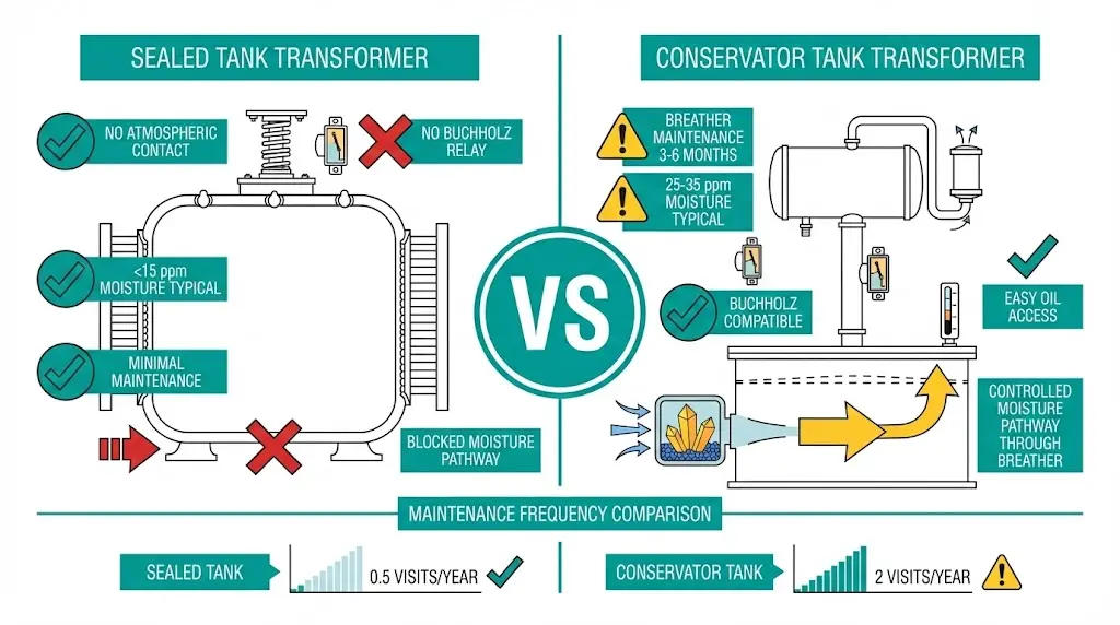
Two dominant designs serve medium-voltage distribution: sealed tanks (hermetically closed with gas cushion) and conservator tanks (expansion vessel with atmospheric breather). Each handles the oil-air interface differently, carrying distinct implications for moisture control, maintenance burden, and total cost of ownership.
This comparison draws from field assessments across 200+ distribution substations in varying climate zones, providing the engineering specificity needed to match tank configuration to your operating environment.

Sealed tank transformers eliminate atmospheric breathing entirely. The design encloses insulating oil within a hermetically welded steel tank, using a compressible gas cushion to accommodate thermal expansion without external air exchange.
Gas-Cushion Operating Principle
At factory assembly, oil fills approximately 70–85% of tank capacity at 25°C reference temperature. The remaining headspace contains dry nitrogen or dehydrated air at 0.02–0.05 MPa gauge pressure. During load cycling, rising oil temperature causes volume expansion. Rather than expelling oil or drawing in atmospheric air, the gas cushion compresses. When load decreases and oil contracts, gas pressure drops correspondingly.
Tank walls must withstand cyclic pressure fluctuations across the transformer’s service life. Two engineering approaches address this:
Operating pressure typically ranges from −30 kPa (vacuum during rapid cooling) to +50 kPa (peak load conditions). A pressure relief device calibrated to 0.7–1.0 bar prevents catastrophic rupture during internal fault events. Per IEC 60076-1 (Power Transformers – General), sealed units must incorporate these relief devices with activation thresholds below structural limits.
Moisture Isolation Performance
With no breathing pathway, sealed tanks block the primary moisture ingress route. Factory-processed oil with moisture content below 10 ppm remains protected throughout service life—field measurements show levels staying below 15 ppm even after 15–20 years, assuming gasket and weld integrity holds.
For distribution applications requiring minimal field maintenance, XBRELE’s oil-immersed transformer configurations include sealed tank designs rated 10 kV through 35 kV class.

Conservator transformers take the opposite approach—rather than resisting atmospheric pressure changes, they accommodate them through a dedicated expansion vessel mounted above the main tank.
Expansion Vessel Mechanics
As oil temperature rises during loading, oil volume increases and flows upward into the conservator through a connecting pipe. When temperature drops, oil returns to the main tank. The conservator volume typically equals 10% of total oil volume, accommodating temperature swings from −25°C to +105°C top-oil temperature without pressurizing the system.
This passive expansion operates at near-atmospheric pressure, simplifying tank fabrication compared to sealed designs. However, the breathing cycle introduces atmospheric air—and its moisture content—into the system.
Silica Gel Breather Function
The critical moisture control component is the silica gel breather mounted at the conservator air intake. As atmospheric pressure changes drive breathing cycles, incoming air passes through desiccant crystals that adsorb water vapor. Standard breathers achieve 90–95% moisture removal efficiency when properly maintained.
The limitation? Silica gel saturates. In tropical climates averaging above 75% relative humidity, breather saturation can occur within 3–6 months without regular inspection. Color-indicating gel (blue/orange when dry, pink/clear when saturated) provides visual status, but requires physical access for verification.
Diaphragm Conservator: The Hybrid Approach
Modern conservator designs incorporate a rubber diaphragm or bladder separating oil from the air space. Air breathes through the silica gel into the space above the diaphragm—but never contacts oil directly. This hybrid achieves moisture levels of 10–15 ppm when properly maintained, approaching sealed-tank performance while retaining conservator benefits.
Understanding transformer oil preservation directly impacts maintenance planning. For technical context on transformer insulation systems, see XBRELE’s guide on power distribution transformers.
[Expert Insight: Field Observations on Moisture Performance]
- Sealed tanks in coastal installations (salt fog exposure) consistently measure below 12 ppm moisture after 10+ years of service
- Basic conservator units in the same environment average 28–35 ppm without monthly breather inspection
- Diaphragm conservators split the difference at 15–20 ppm with quarterly maintenance
- Moisture-related winding failures in our assessment database correlate strongly with conservator units where breather maintenance lapsed beyond 6 months
Moisture degrades transformer insulation through two distinct mechanisms, and understanding both explains why tank design matters so fundamentally.
Dielectric Strength Reduction
Water molecules cluster at oil-paper interfaces, creating localized conductive paths. Breakdown voltage drops measurably with moisture concentration:
IEEE C57.106 (Guide for Acceptance and Maintenance of Insulating Mineral Oil in Electrical Equipment) establishes moisture limits of 35 ppm for transformers rated up to 69 kV—a threshold that basic conservator designs can approach within a decade of service in humid climates.
Cellulose Hydrolysis Acceleration
Paper insulation aging follows Arrhenius kinetics: every 6°C rise in hotspot temperature roughly doubles degradation rate. Moisture presence amplifies this effect by 2–3× at equivalent temperatures through acid-catalyzed hydrolysis of cellulose chains.
A transformer operating at 95°C hotspot with 30 ppm oil moisture ages at roughly the same rate as one operating at 110°C with 10 ppm moisture. Tank design choice, through its moisture control effectiveness, directly influences insulation life expectancy.
Moisture Sources by Tank Design
| Source | Sealed Tank | Basic Conservator | Diaphragm Conservator |
|---|---|---|---|
| Atmospheric breathing | Eliminated | Primary risk | Minimized |
| Gasket/seal degradation | Secondary risk | Secondary risk | Secondary risk |
| Residual moisture in cellulose | Factory-controlled | Factory-controlled | Factory-controlled |
| Condensation from cycling | Minimal (N₂ cushion) | Moderate | Low |
| Parameter | Sealed Tank | Basic Conservator | Diaphragm Conservator |
|---|---|---|---|
| Moisture control | Excellent (<15 ppm typical) | Moderate (25–35 ppm) | Good (15–22 ppm) |
| Atmospheric isolation | Complete | Partial (breather-dependent) | High |
| Oil sampling access | Limited (drain valve) | Easy (conservator drain) | Easy |
| Buchholz relay compatible | No | Yes | Yes |
| Silica gel maintenance | None required | Every 3–6 months | Every 6–12 months |
| Oil expansion capacity | Limited by gas cushion | Large (10% volume) | Large (10% volume) |
| Altitude suitability | Excellent (pressurized) | Good | Good |
| High-humidity performance | Preferred | Requires attention | Suitable |
| On-site oil treatment | Difficult | Easy | Easy |
| Typical rating range | ≤2,500 kVA common | Any rating | ≥1,000 kVA typical |
| Tank fabrication complexity | Higher (pressure vessel) | Lower | Moderate |
| Capital cost | Moderate | Lower | Higher |
| 20-year maintenance cost | Lower | Higher | Moderate |
The maintenance burden difference between tank designs compounds over transformer service life. What appears as minor task frequency variance translates to significant labor cost and reliability divergence across 25–30 years of operation.
Sealed Tank Maintenance Schedule
| Task | Frequency | Notes |
|---|---|---|
| Visual inspection (leaks, PRD condition) | 6 months | Check tank seams, radiator joints, gasket weeping |
| Oil sampling (DGA, moisture, acidity) | 12–24 months | Vacuum-fill sampling kit required to maintain seal |
| PRD function verification | 24–36 months | Replace if resealing mechanism fails test |
| Infrared thermography | 12 months | Detect connection hotspots, internal issues |
| Bushing inspection | 12 months | Check for tracking, contamination, oil level |
Oil sampling requires careful procedure—introducing air during extraction compromises the very moisture barrier the design provides. Vacuum-fill sampling kits maintain seal integrity but add procedural complexity compared to simple drain-valve sampling.
Conservator Tank Maintenance Schedule
| Task | Frequency | Notes |
|---|---|---|
| Silica gel inspection | 3–6 months | Replace when >50% shows color change |
| Oil level verification | 3 months | Compare reading against ambient temperature |
| Buchholz relay inspection | 6 months | Test alarm and trip contact functionality |
| Breather pipe obstruction check | 6 months | Clear debris, verify airflow path |
| Conservator internal cleaning | 5–10 years | Remove sludge accumulation |
| Diaphragm integrity test (if equipped) | 24 months | Pressure decay method |
| Oil sampling | 12 months | Straightforward drain-valve access |
Cost Implications Over 20 Years
For a typical 1,000 kVA distribution transformer:
The labor differential alone—40 fewer site visits over two decades—often exceeds any capital cost premium for sealed designs in remote or difficult-access installations.
[Expert Insight: Maintenance Economics from Utility Assessments]
- One regional utility calculated $180 per conservator maintenance visit versus $220 for sealed-tank oil sampling (specialized equipment)—but visit frequency difference (2× annually vs. 0.5× annually) reversed the lifetime cost advantage
- Silica gel breather failures causing moisture excursions led to three premature winding replacements in a 50-unit conservator fleet over 15 years; zero moisture-related failures in comparable sealed fleet
- Diaphragm conservators showed unexpected value: Buchholz relay detected incipient faults in two units that would have caused catastrophic failure in sealed designs lacking gas accumulation monitoring
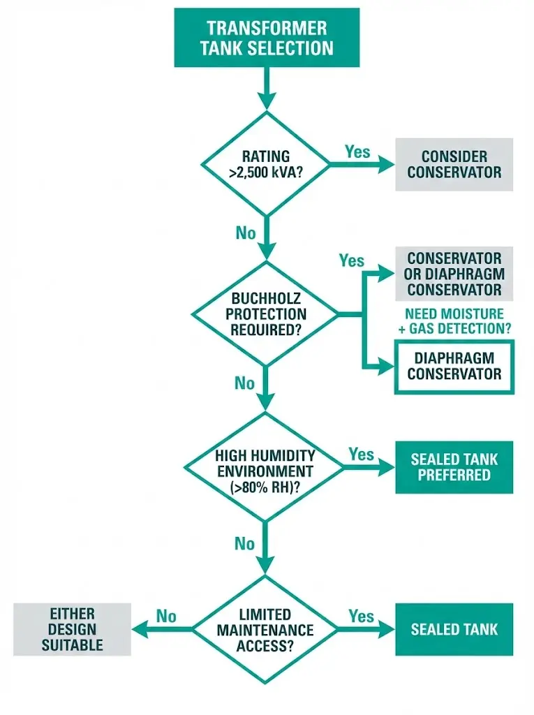
Selection depends on application-specific factors. No single design suits all installations.
Choose Sealed Tank When:
Choose Conservator Tank When:
Choose Diaphragm Conservator When:
XBRELE’s oil-immersed distribution transformer range includes both sealed-tank and conservator configurations from 50 kVA to 2,500 kVA, with diaphragm conservator options available for units ≥500 kVA.
Real-world installation constraints often override theoretical preferences. Environmental factors deserve explicit consideration during specification.
High-Humidity Environments (>80% RH Annual Average)
Basic conservator breathers may saturate within 2–3 months during monsoon seasons, even with monthly inspection schedules. Maintenance teams either increase visit frequency dramatically or retrofit to diaphragm conservators mid-life. Sealed tanks eliminate this variable entirely—a compelling advantage where site access involves significant travel or safety protocols.
High-Altitude Installations (>1,000 m)
Reduced atmospheric pressure affects both designs differently:
Above 3,000 m, most manufacturers recommend sealed tank designs or conservators with enhanced breathing systems. [VERIFY STANDARD: IEC 60076-11 for specific altitude correction methodology]
Extreme Temperature Cycling
Desert installations experiencing 45°C+ daytime temperatures and near-freezing nights impose aggressive oil expansion/contraction cycles. Conservator systems handle these wider thermal excursions more gracefully—the 10% volume reserve accommodates extremes that might challenge gas-cushion designs sized for temperate climates.
Seismic Zones
Conservator tanks add height and shift center of gravity upward, complicating seismic bracing design. Sealed tanks offer lower profiles and simpler mounting configurations. For installations requiring IEEE 693 seismic qualification, structural analysis must account for conservator mass and moment arm during ground acceleration events.
XBRELE manufactures oil-immersed distribution transformers with both tank architectures, engineered for IEC 60076 compliance and adapted for challenging field conditions across global markets.
Available Configurations:
Ready to specify the right tank design for your project?
Contact XBRELE’s engineering team for application review and quotation: Distribution Transformer Manufacturer
Q: How much does moisture content affect transformer service life?
A: Oil moisture at 30 ppm versus 10 ppm can reduce insulation life expectancy by 40–50% at typical operating temperatures, with the effect compounding as hotspot temperatures increase above 85°C.
Q: Can I retrofit a basic conservator with a diaphragm system?
A: Many manufacturers offer diaphragm retrofit kits for existing conservator tanks, though the modification requires draining oil, inspecting internal surfaces, and factory-certified installation to ensure proper sealing.
Q: Why can’t sealed tank transformers use Buchholz relay protection?
A: Buchholz relays require a gas accumulation space connected to the main tank via a pipe—the conservator connection. Sealed tanks lack this pathway, making gas-based fault detection impossible with standard Buchholz devices.
Q: What happens if a sealed tank’s pressure relief device activates?
A: The PRD vents gas to prevent tank rupture, but this breaks the hermetic seal. Self-resealing PRDs restore integrity after minor events, while non-resealing types require field service or factory reconditioning to restore moisture protection.
Q: How do I know when conservator silica gel needs replacement?
A: Color-indicating silica gel changes from blue or orange (dry) to pink or colorless (saturated). Industry practice recommends replacement when more than half the visible gel shows color change, or immediately if oil moisture tests exceed acceptable limits.
Q: Are sealed tanks suitable for transformers larger than 2,500 kVA?
A: Sealed designs become less practical above 2,500 kVA because oil volume expansion requires either very large gas cushions or extremely robust pressure vessel construction, both adding significant cost compared to conservator alternatives.
Q: Which design requires less specialized maintenance training?
A: Conservator systems use familiar components (breathers, level gauges, relay contacts) serviceable by general electrical maintenance staff, while sealed tank oil sampling requires vacuum-extraction equipment and procedures to avoid compromising the hermetic seal.