Need Full Specifications?
Download our 2025 Product Catalog for detailed drawings and technical parameters of all switchgear components.
Get Catalog
Download our 2025 Product Catalog for detailed drawings and technical parameters of all switchgear components.
Get Catalog Download our 2025 Product Catalog for detailed drawings and technical parameters of all switchgear components.
Get Catalog
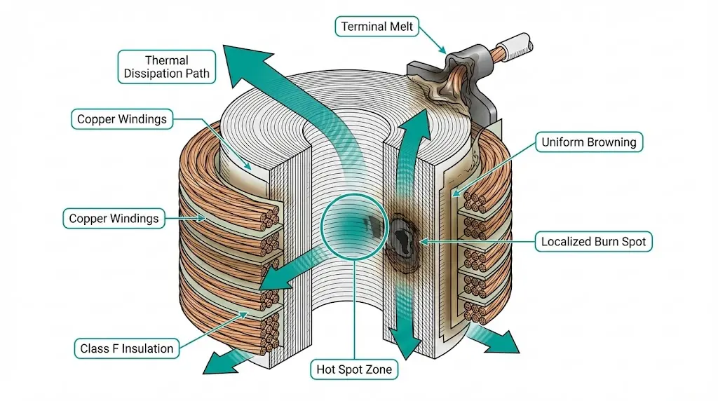
A burned operating coil at 2 AM means one thing: emergency callout, production losses, and unanswered questions about what went wrong.
Coil burnout in medium-voltage switchgear ranks among the most frustrating failure modes. Unlike gradual contact erosion or predictable insulation aging, coil failures often strike without warning. The breaker that operated flawlessly yesterday refuses to close today. The contactor that switched thousands of times suddenly welds itself silent.
The consequences extend beyond inconvenience:
In field assessments across industrial facilities, coil failures account for approximately 35% of all contactor-related downtime. Most trace back to three root causes: voltage abnormalities, thermal accumulation, and control circuit faults. Each leaves distinct forensic signatures that enable targeted prevention.
Coil burnout occurs when electromagnetic coils experience insulation degradation beyond recovery—typically through thermal runaway or dielectric breakdown. The fundamental physics centers on Joule heating: electrical energy converting to thermal energy as current passes through copper windings.
The heat generated in a coil follows Joule’s law: Q = I²Rt, where Q represents thermal energy in joules, I is the current in amperes, R is coil resistance in ohms (Ω), and t is time in seconds. When this thermal output exceeds the coil’s dissipation capacity—typically rated at 10–15 W for standard AC contactor coils—temperatures rise beyond the insulation’s thermal limit.
Every electromagnetic coil operates within a thermal equilibrium where heat generated must equal heat dissipated. Disturb this balance, and degradation begins.
According to IEC 60947-4-1 (contactors and motor starters), Class B insulation coils must not exceed continuous operating temperatures of 130°C, while Class F coils tolerate up to 155°C. Field observations consistently show that exceeding these thresholds by even 10°C reduces coil lifespan by approximately 50%—a relationship governed by the Arrhenius equation for insulation aging.
The electromagnetic mechanism itself contributes to burnout risk. During normal operation, AC coils in a vacuum circuit breaker draw inrush current 6–10 times their sealed current rating. If the armature fails to close completely—due to contamination, mechanical binding, or insufficient voltage—the coil remains in high-current inrush mode. Catastrophic overheating follows within 30–60 seconds.

Voltage-related coil failures follow two distinct patterns, each leaving identifiable forensic evidence.
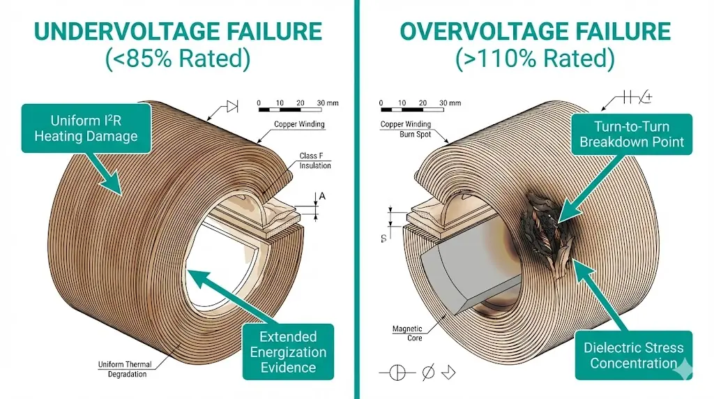
Undervoltage conditions cause incomplete armature pull-in, resulting in elevated inrush currents persisting beyond the normal 30–50 ms pickup time. This extended high-current state generates excessive I²R losses in the copper windings.
At 80% rated voltage, a closing coil may draw 120–140% of normal operating current. The mechanism moves slower, extending energization time. Combined effects multiply rapidly:
Repeated undervoltage operations progressively degrade winding insulation. Forensic examination reveals uniform browning throughout the coil—a signature distinct from localized hot spots.
Overvoltage stress accelerates insulation aging through enhanced electric field intensity across turn-to-turn spacing. According to IEC 60947-4-1, coils must tolerate 110% rated voltage continuously. However, transient overvoltages reaching 150–200% during capacitor switching or load rejection events create localized dielectric stress concentrations exceeding 3 kV/mm in standard Class F insulation systems.
At 120% voltage:
The most insidious overvoltage damage occurs in the first few milliseconds. Insulation between turns experiences dielectric stress before thermal effects even begin. Inter-turn shorts develop, creating localized heating that cascades into full failure.
[Expert Insight: Voltage Monitoring Strategy]
- Install power quality recorders on control circuits for 7–14 days to capture transient events
- Document voltage during motor starting, fault clearing, and load shedding—these events stress coils most
- Target steady-state voltage between 95–105% of coil rating for optimal service life
- Consider capacitor-backed DC supplies for critical applications with unstable control voltage
The Arrhenius relationship governs insulation thermal aging: for every 10°C rise above rated temperature, insulation life approximately halves. Class F insulation (155°C rating) operating continuously at 175°C experiences a life reduction factor of 4×, dropping from typical 20-year service to under 5 years.
A coil rated for 40°C ambient operating at 55°C ambient loses approximately 50% of its thermal margin. Testing in enclosed panel environments showed internal temperatures reaching 45–55°C above ambient, pushing coil hot-spot temperatures dangerously close to thermal limits during repeated switching cycles.
For vacuum contactor applications with continuous holding coils, this ambient derating becomes critical. A Class F holding coil operating at 50°C ambient has only 105°C temperature rise available—easily exceeded during high-duty-cycle operations.
Closing coil specifications typically assume intermittent duty: one operation, followed by sufficient cooling time. Rapid sequential operations—common during commissioning tests or reclosing sequences—accumulate heat faster than dissipation allows.
Consider an auto-reclose sequence: close-open-close-open-close (O-0.3s-CO-15s-CO). The closing coil energizes three times within 16 seconds. Without adequate thermal mass or forced cooling, winding temperature can exceed limits by the third operation.
Switchgear installed in sealed enclosures, outdoor kiosks, or underground vaults faces restricted heat dissipation. Convective cooling, which removes 60–70% of coil heat under normal conditions, becomes severely limited.
Field observation: Coil failures cluster in bottom-tier breaker compartments of vertically-stacked switchgear lineups. Heat from equipment rises, but lower units suffer most from restricted airflow beneath the floor.
Control circuit anomalies cause coil burnout even when voltage and temperature remain within specifications. The common thread: extended energization time.
Auxiliary contacts (52a, 52b designations) signal breaker position to the control circuit. When a closing coil energizes, the 52a contact should open to interrupt coil current once the mechanism latches.
Worn or misadjusted auxiliary contacts create several failure modes:
A closing coil designed for 100 ms duty operating for 500 ms experiences five times the thermal stress. Three or four such events can initiate insulation failure.
Anti-pumping circuits prevent repeated closing attempts if the breaker trips immediately after closing. When this protection fails, the closing coil may energize repeatedly—destroying coils within seconds.
Per IEC 62271-100 operating mechanism requirements, the anti-pumping relay must block closing commands until the close signal is removed and the breaker reaches full open position.
The interaction between electrical and thermal stresses creates synergistic damage. Partial discharge activity initiates at voltages as low as 1.5× rated in thermally aged insulation, compared to 2.5× in new coils. This reduced partial discharge inception voltage indicates compromised dielectric integrity, often preceding complete burnout by 2–6 months in high-duty applications.
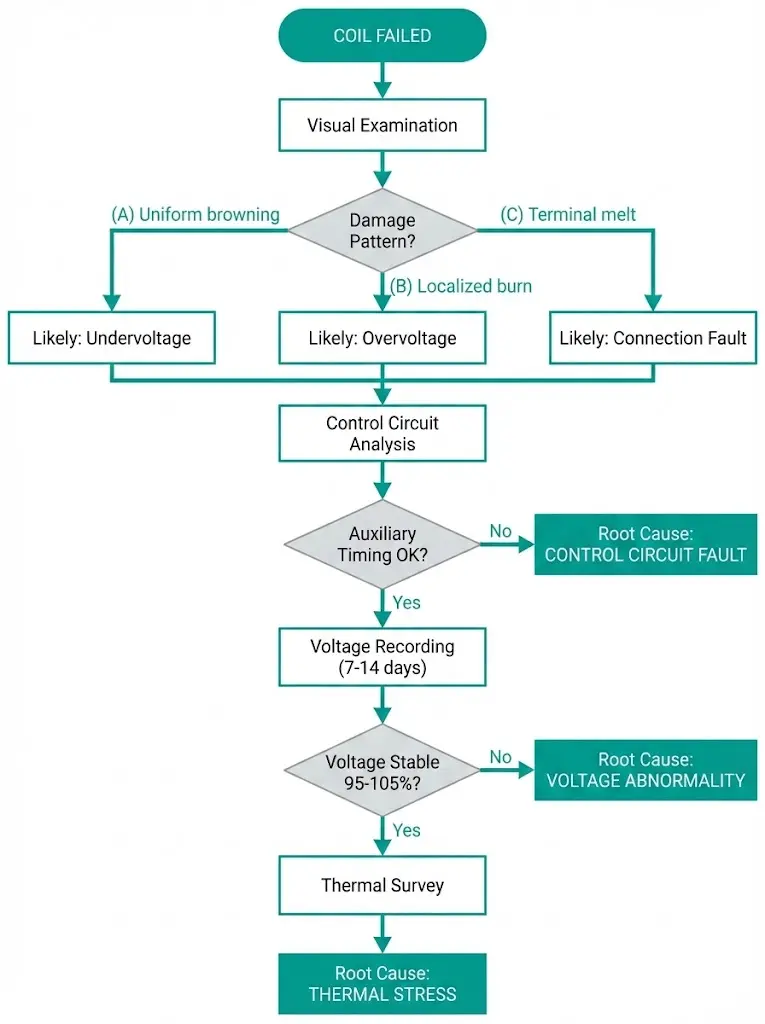
Systematic diagnosis distinguishes between voltage, thermal, and control-induced failures—essential for preventing recurrence.
Remove the failed coil and examine insulation condition:
| Observation | Likely Cause |
|---|---|
| Uniform browning/charring throughout winding | Undervoltage (extended I²R heating) |
| Localized burn near inner turns | Overvoltage (turn-to-turn breakdown) |
| Melted termination or lead wires | Loose connection (high-resistance joint) |
| External char near core | Ambient overtemperature |
Before installing a replacement coil:
Install a power quality recorder on the control voltage supply for 7–14 days. Document steady-state voltage, transient dips during motor starting or fault clearing, and voltage rise after load shedding events.
Use infrared thermography during normal operations to measure coil surface temperature and terminal connection temperatures.
[Expert Insight: Commissioning Verification Checklist]
- Record coil current waveform during three consecutive operations
- Measure voltage at coil terminals (not at panel supply) during operation
- Verify auxiliary contact timing with ±5 ms accuracy
- Thermal cycle test: five operations at rated duty, monitor coil temperature rise
- Document all measurements for baseline comparison during future troubleshooting
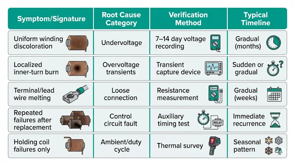
This diagnostic reference table connects observable symptoms to underlying coil burnout root causes:
| Symptom/Signature | Root Cause Category | Verification Method | Typical Timeline |
|---|---|---|---|
| Uniform winding discoloration | Undervoltage | 7–14 day voltage recording | Gradual (months) |
| Localized inner-turn burn | Overvoltage transients | Transient capture device | Sudden or gradual |
| Terminal/lead wire melting | Loose connection | Resistance measurement | Gradual (weeks) |
| Repeated failures after replacement | Control circuit fault | Auxiliary timing test | Immediate recurrence |
| Holding coil failures only | Ambient/duty cycle | Thermal survey | Seasonal pattern |
Addressing coil burnout requires matching solutions to identified root causes.
| Problem | Solution |
|---|---|
| Chronic undervoltage | Install buck-boost transformer on control circuit |
| Transient dips during faults | Add capacitor-supported DC supply |
| Overvoltage from generator excitation | Adjust AVR settings; install surge suppressor |
For critical applications, specify coils with wider voltage tolerance (75–110% AC or DC coils with electronic drivers).
Specify quality switchgear auxiliary components from the initial design phase:
Review switchgear components specifications to ensure compatibility with your application requirements.
Coil reliability begins at equipment specification. Key parameters to verify:
Engineering teams benefit from working with an established switchgear manufacturer who provides detailed operating mechanism documentation, thermal test reports, and application engineering support. The marginal cost difference between premium and economy coil systems disappears after a single emergency replacement event.
Q: What percentage of coil failures result from voltage problems versus thermal issues?
A: Field data suggests voltage abnormalities cause approximately 40–50% of coil burnout cases, thermal stress accounts for 30–35%, and control circuit faults contribute 15–25%, though these factors often overlap in complex failure scenarios.
Q: How quickly can undervoltage damage a closing coil?
A: A single severe undervoltage event (below 75% rated) can cause immediate failure, while moderate undervoltage (80–85% rated) typically degrades insulation progressively over dozens to hundreds of operations before burnout occurs.
Q: Can I use a higher-rated coil voltage to prevent overvoltage damage?
A: Specifying a coil with 10–15% higher voltage rating than the supply provides margin against transients, but excessively high ratings cause undervoltage symptoms—the coil may fail to pull in reliably at normal operating voltage.
Q: What auxiliary contact resistance indicates replacement is needed?
A: Contact resistance exceeding 500 mΩ when closed suggests significant wear; replace contacts showing resistance above 1 Ω or evidence of pitting, as high resistance creates voltage drops affecting coil performance.
Q: How does altitude affect coil thermal performance?
A: Above 1,000 meters elevation, reduced air density decreases convective cooling efficiency by approximately 1% per 100 meters, requiring thermal derating or enhanced ventilation for coils operating near their thermal limits.
Q: What is the typical warning time before coil burnout?
A: Gradual failures from thermal or undervoltage stress often show 2–6 months of declining performance (slower operation, occasional misfires) before complete failure, while control circuit faults or severe overvoltage can cause immediate burnout without warning.
Q: Should I replace both closing and trip coils when one fails?
A: If root cause analysis indicates systemic issues (voltage problems, ambient temperature), replacing both coils and addressing the underlying cause prevents near-term failure of the remaining coil; isolated mechanical or connection failures may not require paired replacement.