Need Full Specifications?
Download our 2025 Product Catalog for detailed drawings and technical parameters of all switchgear components.
Get Catalog
Download our 2025 Product Catalog for detailed drawings and technical parameters of all switchgear components.
Get Catalog Download our 2025 Product Catalog for detailed drawings and technical parameters of all switchgear components.
Get Catalog
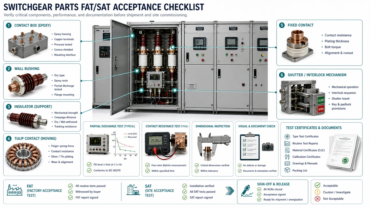
A switchgear parts FAT/SAT acceptance checklist is a structured, sequential verification document used to confirm that individual switchgear components – including contact boxes, bushings, insulators, and interlocks – meet defined electrical, mechanical, and dimensional tolerances before energization. FAT (Factory Acceptance Test) is performed at the manufacturer’s facility against the purchase specification and applicable standards such as IEC 62271 or IEEE C37. SAT (Site Acceptance Test) is performed after delivery and installation to confirm that transport, handling, and field assembly have not introduced faults or deviations.
This guide focuses on troubleshooting failed results, diagnosing root causes, and completing acceptance records that will hold up under audit or incident review.
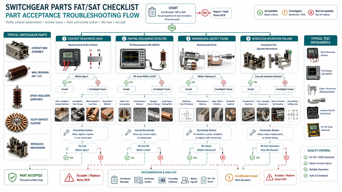
Before opening a component or escalating an NCR, run through the table below. It maps the most common failure symptoms to a first test, probable root cause, and next action.
| Symptom | First Test | Likely Root Cause | Next Action |
|---|---|---|---|
| Contact resistance above FAT limit | Re-measure with clean probe tips; verify 100 A DC injection | Oxidized or pitted contact surface; loose bolted joint | Visual inspection at 10x; clean, re-torque, retest |
| Insulation resistance below 1000 Mohm in dry environment | Retest after 2 h surface drying; record humidity | Internal void, crack, or resin delamination | PD test or hi-pot; escalate to manufacturer if confirmed |
| Insulation resistance below 1000 Mohm in humid environment | Clean surface, dry 24 h at ambient, retest | Surface contamination or moisture absorption | Retest within 24 h before re-contamination |
| Tan delta above alarm threshold | Repeat at 0.5 U0 and U0; check tip-up effect | Internal moisture ingress or voids in cast resin | PD measurement; reject if tip-up > 0.1% |
| Mechanical interlock does not block unauthorized sequence | Measure blocking pin engagement depth vs. drawing | Worn cam or pin below minimum engagement | Replace blocking element; retest 5 sequences |
| Interlock blocks authorized operation (false inhibit) | Check actuator arm travel; feeler-gauge switch trip point | Misaligned position switch; stiction from dry lubricant | Realign switch; lubricate; retest full sequence |
| Thermal camera shows > 15 deg C phase differential at SAT | Measure contact resistance on hot phase before next shift | High-resistance joint at contact box | De-energize; inspect and clean contact; retest |
| Anti-pumping relay fails – CB re-closes on sustained close | Energize anti-pump coil manually; verify NC contact opens | Welded contact or coil failure | Replace relay; rewire check; retest per C37.09 |
| Hi-pot leakage current steps during 60 s withstand | Do not re-apply voltage; note step magnitude and time | Dielectric breakdown initiation | Replace component unconditionally; raise NCR |
Test results are only as defensible as the instruments and standards behind them. The table below identifies each required tool, its measurement function, and the authority source used to set acceptance criteria.
| Instrument / Source | Function | Acceptance Authority |
|---|---|---|
| Micro-ohmmeter (100 A DC rated) | Contact resistance in micro-ohm | IEC 62271-200; OEM contact resistance datasheet |
| 5 kV or 10 kV megohmmeter | Insulation resistance (IR) and Polarization Index | IEC 60052; IEEE 43 |
| Capacitance and power factor test set | Tan delta / dissipation factor | IEC 60137; IEEE C57.19.01 |
| AC or DC hi-pot test set (rated to voltage class) | Power-frequency withstand; leakage current monitoring | IEC 62271-1 Clause 7; IEC 60060-1; ANSI/IEEE C37.09 |
| PD measuring system (IEC 60270 calibrated, in pC) | Partial discharge inception and level | IEC 60270; IEC 60137; IEC 62271-203 |
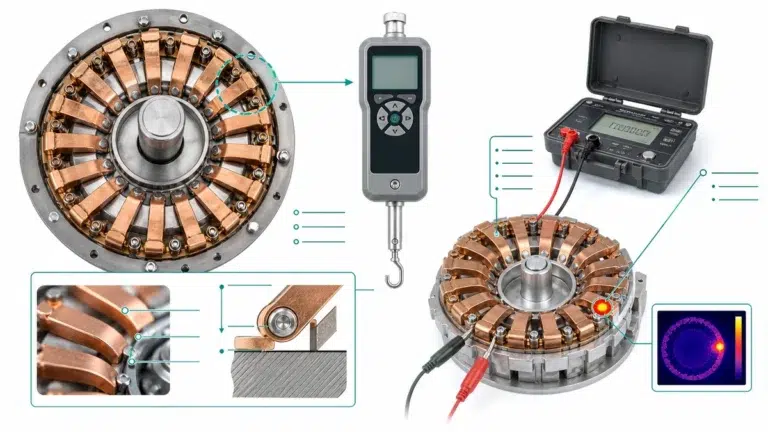
| Calibrated push-pull gauge | Contact spring force; interlock blocking force | OEM type-test drawing; IEC 62271-200 |
| Thermal imaging camera | Phase-to-phase temperature differential at SAT | NFPA 70B (maintenance reference); IEC 60076-7 analogy |
| Digital timer or oscilloscope | Interlock signal response time | Scheme logic specification; IEC 62271-100 |
| Insulation resistance tester (secondary injection) | Auxiliary contact chain continuity and open-circuit state | As-built wiring diagram; OEM control schematic |
| Calibration certificates (all instruments) | Traceability of measured values | ISO/IEC 17025 accredited calibration body |
| OEM assembly drawing and maintenance manual | Dimensional tolerances; torque values; lube specifications | OEM document; contract purchase specification |
| IEC 62271 series / ANSI/IEEE C37 series | Electrical acceptance criteria | IEC, IEEE (external authority) |
| Project specification and single-line diagram | Site-specific derating, altitude correction, pollution class | Owner’s engineer; EPC contract |
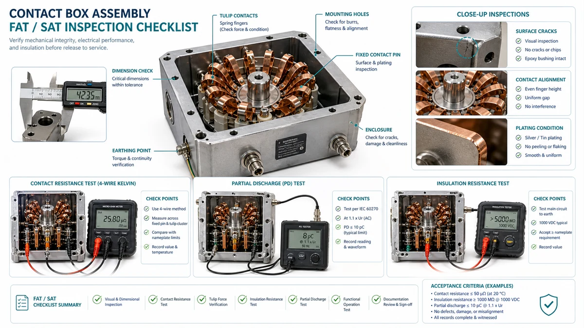
The contact box is the load-bearing heart of any switchgear assembly. Failures here – burned contact fingers, loose spring clusters, misaligned entry guides – produce resistive heating that cascades into insulation breakdown and eventual busbar faults.
| Contact Rating | Minimum Spring Force | Maximum Spring Force |
|---|---|---|
| Up to 630 A | 18 N per finger | 28 N per finger |
| 630 A – 1600 A | 25 N per finger | 40 N per finger |
| 1600 A – 4000 A | 35 N per finger | 55 N per finger |
| Contact Assembly Type | FAT Pass Limit | SAT Pass Limit | Flag for Investigation |
|---|---|---|---|
| Plug-in contact (up to 1600 A) | <= 50 micro-ohm | <= 75 micro-ohm | > 100 micro-ohm |
| Draw-out contact (1600 A – 4000 A) | <= 30 micro-ohm | <= 45 micro-ohm | > 60 micro-ohm |
| Bolted contact | <= 10 micro-ohm | <= 15 micro-ohm | > 20 micro-ohm |
| Phase-to-Phase Differential | Interpretation | Action |
|---|---|---|
| < 5 deg C | Normal | Document and archive |
| 5 deg C – 15 deg C | Marginal | Schedule inspection at first maintenance window |
| > 15 deg C | Abnormal | De-energize and inspect contact resistance; do not defer |
| Inspection Item | FAT Required | SAT Required | Failure at FAT | Failure at SAT |
|---|---|---|---|---|
| Visual – contact fingers | Yes | Yes | Hold shipment | De-energize; rectify |
| Spring force | Yes | Spot-check (20%) | Reject assembly | Replace springs before energizing |
| Contact resistance | Yes | Yes | Reject assembly | Do not energize |
| Draw-out alignment | Yes | Yes | Adjust at factory | Adjust on site |
| Thermal scan | No | Yes | N/A | De-energize if > 15 deg C delta |
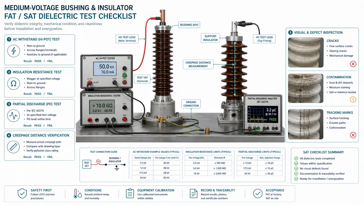
Bushings and insulators are dielectric components under continuous mechanical and electrical stress. Failures in this group are typically silent until flashover or tracking causes a forced outage.
| Condition | PI Value | Interpretation | Action |
|---|---|---|---|
| Dry and clean insulation | >= 4.0 | Good dielectric condition | Accept |
| Marginal (possibly damp or aged) | 2.0 – 3.9 | Monitor; retest after drying | Conditional accept at FAT; retest at SAT |
| Contaminated or degraded | 1.0 – 1.9 | Surface leakage or internal moisture | Reject; investigate and replace |
| Severe degradation | < 1.0 | Active fault path | Reject unconditionally |
| Bushing/Insulator Type | Maximum Tan delta at 20 deg C | Alarm Threshold | Reject Threshold |
|---|---|---|---|
| Oil-impregnated paper (OIP) bushing | <= 0.5% | 0.5 – 0.7% | > 0.7% |
| Resin-bonded paper (RBP) bushing | <= 0.8% | 0.8 – 1.2% | > 1.2% |
| Cast resin / epoxy insulator | <= 1.0% | 1.0 – 1.5% | > 1.5% |
| Porcelain insulator (dry) | <= 0.5% | 0.5 – 0.8% | > 0.8% |
| Silicone composite insulator | <= 0.3% | 0.3 – 0.5% | > 0.5% |
| Voltage Class (kV rated) | IEC PFWV (kV rms) | SAT Applied Voltage (80%) | DC Equivalent (x1.414) |
|---|---|---|---|
| 7.2 kV | 20 kV | 16 kV | 22.6 kV DC |
| 12 kV | 28 kV | 22.4 kV | 31.7 kV DC |
| 24 kV | 50 kV | 40 kV | 56.6 kV DC |
| 36 kV | 70 kV | 56 kV | 79.2 kV DC |
| 52 kV | 95 kV | 76 kV | 107.5 kV DC |
| Component | PD Inception Voltage (minimum) | Maximum Permissible PD Level |
|---|---|---|
| GIS spacer insulator | >= 1.2 x U0 | <= 5 pC at 1.1 x U0 |
| Epoxy cast bushing >= 12 kV | >= 1.1 x U0 | <= 10 pC at U0 |
| OIP condenser bushing | >= 1.1 x U0 | <= 10 pC at U0 |
| Composite hollow insulator | >= 1.0 x U0 | <= 20 pC at U0 |
Interlock failures are disproportionately responsible for maintenance incidents because the fault often stays latent – appearing functional under routine observation but failing precisely when a protection sequence is triggered under load or fault conditions.
| Interlock Type | Test Action | Acceptance Criterion | Failure Mode Detected |
|---|---|---|---|
| Mechanical key interlock | Attempt all unauthorized sequences; confirm only correct key sequence releases mechanism | Zero unauthorized operations complete | Key wear allowing partial engagement; incorrect key series installed |
| Stored-energy interlock (spring-charged) | Attempt close with spring discharged; verify blocking pin engages | Close command does not complete; pin travel >= design specification (typically 8-12 mm) | Worn blocking pin; spring position switch misaligned |
| Earth switch / CB interlock | With CB closed, attempt earth switch close; with earth switch closed, attempt CB close | Both sequences mechanically blocked | Worn cam profile; interlock bar corrosion causing sticking or false release |
| Withdraw / rack-out interlock | Rack to test position; confirm CB cannot close; rack to service position; retest | CB close inhibited in test and disconnect positions | Position detection switch drift; misaligned actuator arm |
| Door / panel interlock | Open LV compartment door with CB in service; verify CB close blocked | Electrical close inhibited within <= 100 ms of door open signal | Auxiliary contact oxidation; door switch misalignment after panel flexing |
| Anti-pumping relay interlock | Apply sustained close pulse; verify CB closes once and does not re-close | Single close operation only during sustained close command | Anti-pump relay coil failure; wiring error bypassing relay |
| Electrical interlock (auxiliary contact chain) | Inject test signals into interlock auxiliary contact string; verify logic output | Correct continuity in permissive chain; broken chain produces correct inhibit output | Auxiliary contact bounce; loose termination under vibration |
Mechanical interlock does not block unauthorized operation: Measure blocking pin engagement depth against the type-test drawing; replace worn blocking element and verify the part number against the cubicle serial drawing before installation.
Interlock blocks authorized operation (false inhibit): Check actuator arm travel against nominal and verify the position switch trip point with a feeler gauge or dial indicator; realign, clean, and re-lubricate before retesting the full sequence.
| Condition | FAT Disposition | SAT Disposition |
|---|---|---|
| Mechanical blocking force below 80% of specified | Reject – return for mechanism replacement | Reject – do not energize; quarantine cubicle |
| One unauthorized sequence partially completes | Reject – root cause investigation required | Reject – do not energize |
| Auxiliary contact resistance 0.5 – 1.0 ohm | Conditional pass – document and retest after 24 h soak | Fail – clean contacts and retest before energization |
| Auxiliary contact resistance > 1.0 ohm | Reject | Reject |
| Timing outside specification but within 2x | Conditional – identify cause before shipment | Fail – identify and correct before energization |
| Anti-pump test fails | Reject | Reject – do not energize under any circumstance |
| Voltage-check interlock wrong output for one condition | Reject | Reject |
Background: During SAT on a 24 kV draw-out switchgear panel at a new industrial substation, the commissioning team measured contact resistance on the three-phase plug-in contact assemblies of one circuit breaker. Ambient temperature was 28 deg C and relative humidity was 62%.
Measured evidence:
| Phase | FAT Result (micro-ohm) | SAT Result (micro-ohm) | SAT Limit (micro-ohm) | Status |
|---|---|---|---|---|
| L1 | 38 | 44 | <= 75 | Pass |
| L2 | 41 | 112 | <= 75 | FAIL |
| L3 | 39 | 47 | <= 75 | Pass |
Diagnosis: The disproportionate delta on L2 only, with no temperature-correction factor large enough to explain a 71 micro-ohm shift at 28 deg C, pointed to a localized condition. Visual inspection under 10x magnification revealed a thin layer of metallic powder on the fixed contact pin of the L2 tulip cluster, consistent with corrosion product from a corroded transit bracket stored adjacent to the contact pin in the shipping crate. The contact surface showed no pitting or arc erosion.
| Phase | Post-Clean SAT Result (micro-ohm) | SAT Limit (micro-ohm) | Status |
|---|---|---|---|
| L1 | 43 | <= 75 | Pass |
| L2 | 46 | <= 75 | Pass |
| L3 | 45 | <= 75 | Pass |
Every row in the checklist should represent one discrete test or inspection activity.
| Column | Content Required | Notes |
|---|---|---|
| Item No. | Sequential reference (e.g., CB-01, BU-03) | Ties to drawing/BOM reference |
| Component | Contact box / Bushing / Insulator / Interlock | Use standardized naming |
| Test/Inspection Activity | Specific action performed | “IR test phase-to-earth” not “insulation check” |
| Applicable Standard | IEC / IEEE / ANSI clause number | Mandatory; internal spec alone is insufficient |
| Acceptance Criterion | Numeric limit or go/no-go condition | e.g., >= 1000 Mohm at 1 kV DC, 1 min |
| Measured / Observed Value | Actual result with units | Never leave blank; enter N/A with justification |
| Pass / Fail / Conditional | Disposition | Conditional requires NCR reference |
| Test Instrument ID | Asset tag and calibration due date | Calibration expiry voids result |
| Inspector Name and Signature | Printed name + wet or electronic signature | Electronic must meet audit-trail standard |
| Date and Time | DD/MM/YYYY HH:MM | Time matters for thermal/humidity correlation |
| Witness (if required) | Client or third-party name and signature | Required at hold points |
| NCR / Deviation Reference | Nonconformance report number | Leave blank if clean pass |
| Remarks | Ambient conditions, anomalies, retest notes | Mandatory if result is borderline |
Use as Is (UAI): Applicable only when the deviation is quantified, an engineering analysis confirms it does not affect safety or rated performance, and the owner’s engineer provides written concurrence.
Rework: Applicable when the failure mode is surface-level, the corrective action is defined and reversible, and the reworked parameter can be fully retested. The original failed record is retained and cross-referenced to the new test record.
| Hold Point | Triggered By | Required Signatory |
|---|---|---|
| Pre-test inspection complete | Before any energized test | OEM QA + Client Witness |
| HV withstand test | Before applying test voltage | OEM QA + Client Witness |
| Final functional test | After all corrections closed | OEM QA + Client Witness |
| FAT certificate issuance | All rows passed or NCRs closed | OEM QA Manager + Client Representative |
| SAT energization approval | All site tests complete | Site Engineer + Client O&M Representative |
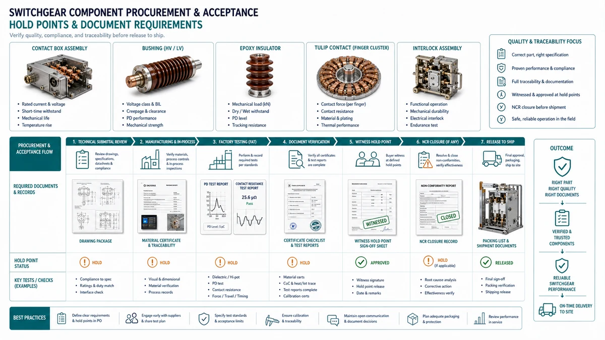
Procurement failures that surface during FAT or SAT – wrong creepage distance, mismatched contact rating, undocumented insulator material – cost more to fix in the field than they would have cost to specify correctly at the order stage.
| Criterion | Minimum Acceptable | Reason to Reject |
|---|---|---|
| Test certificates | Per-unit or per-lot certificates traceable to serial number | Certificates issued to a product family without batch traceability |
| Material declarations | Full composition with alloy/polymer grade specified | “Equivalent to OEM” without documented composition |
| Dimensional documentation | Certified drawings with tolerances | Sketches or nominal dimensions only |
| Quality system | ISO 9001 certified scope covering the specific component | Certification scope excludes manufacturing of the ordered part |
| FAT participation | Supplier technical representative available during FAT | FAT support only by distributor with no factory access |
| Spare parts commitment | Minimum 10-year availability stated in contract | No written commitment beyond current catalog availability |
| Type test evidence | IEC or ANSI type test reports less than 10 years old | Type tests conducted on a different voltage or current rating than ordered |
Creepage or BIL mismatch: If the supplier datasheet creepage distance or BIL rating does not match the site specification, request a revised datasheet with correct values or order from a different supplier. Do not accept verbal assurance.
Missing or unverifiable test certificates: If per-unit test data cannot be traced to the specific serial numbers being shipped, arrange third-party inspection at the factory or reject and reorder.
Use these XBRELE references to connect the field decision to the correct product, test, and procurement workflow: XBRELE product page, XBRELE vacuum circuit breaker range, VCB ratings guide, VCB FAT/SAT acceptance checklist, XBRELE switchgear parts range.
For external method context, compare the site procedure with the public IEEE C37.09 standards page and then apply the exact OEM manual and project specification for the supplied equipment.
Field example: during a service inspection, one phase measured outside its commissioning baseline while the other two phases remained stable. The team repeated the measurement with verified leads, checked timing and contact travel, and used the measured divergence to separate a contact-pressure problem from a generic surface-cleaning issue.
FAT (Factory Acceptance Test) is performed at the manufacturer’s facility and verifies that the component meets the purchase specification, applicable standards, and type-test compliance under controlled conditions. SAT (Site Acceptance Test) is performed after delivery and installation to confirm that transport, handling, and field assembly have not introduced faults.
For plug-in contacts rated up to 1600 A, the SAT pass limit is <= 75 micro-ohm. For draw-out contacts rated 1600 A–4000 A, the SAT pass limit is <= 45 micro-ohm.
Yes, under specific conditions. A bushing that fails IR on first test but passes after surface cleaning and a 24 h drying period has a contamination failure mode, not a materials failure; document the cleaning procedure, re-run the full IR and withstand sequence, and record both results.