Need Full Specifications?
Download our 2025 Product Catalog for detailed drawings and technical parameters of all switchgear components.
Get CatalogDownload our 2025 Product Catalog for detailed drawings and technical parameters of all switchgear components.
Get CatalogDownload our 2025 Product Catalog for detailed drawings and technical parameters of all switchgear components.
Get Catalog
Engineering Verdict: Power (VA) remains approximately constant on both sides (minus losses). Selection depends on your node in the grid and load-end requirements.
In the rigorous field of power systems engineering, the ability to manipulate voltage is not merely a convenience—it is a fundamental requirement for grid stability and economic viability. The transition from generation to consumption relies on the strategic deployment of the step up transformer and the step down transformer. While the underlying physics—Faraday’s Law of Induction—remains constant, the engineering specifications, insulation coordination, and thermal management strategies for these two classes of equipment differ drastically depending on their role in the network.
For EPC contractors, utility engineers, and technical procurement managers, selecting between a step up transformer and a step down transformer involves more than just looking at a nameplate voltage. It requires an understanding of how these units interface with the broader grid, handle short-circuit stresses, and manage losses over a 25-to-30-year lifecycle. This article provides an authoritative analysis of these critical components within the context of MV/HV power distribution.
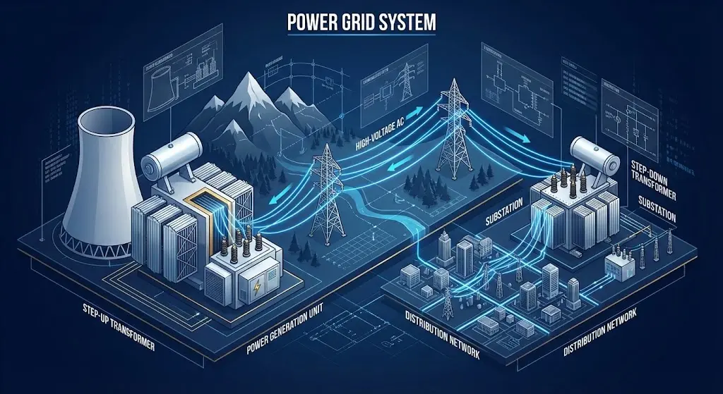
To understand why we distinguish between step-up and step-down configurations, we must first address the “Transmission Dilemma.” In any long-distance conductor, energy is lost as heat. This physical reality is governed by specific electrical relationships that dictate why high voltage is mandatory for efficiency.
The engineering formula for power loss in a conductor is defined as:
Ploss = I2R
To deliver the same amount of real power, we use the following relationship:
P = V × I × cos(φ)
By increasing the voltage (V), we can significantly decrease the current (I) for the same power (P), thereby reducing the squared heating losses (I2) in the transmission infrastructure.
This is the primary driver for the step up transformer at the generation stage and the subsequent series of step down transformer units throughout the distribution hierarchy. It is a common misconception among non-engineers that transformers “create” power. In reality, a transformer is a passive impedance-matching device. From a field perspective, we treat it as a high-efficiency converter that exchanges current for voltage (or vice versa) while maintaining a near-constant power throughput, minus hysteresis, eddy current, and ohmic losses.
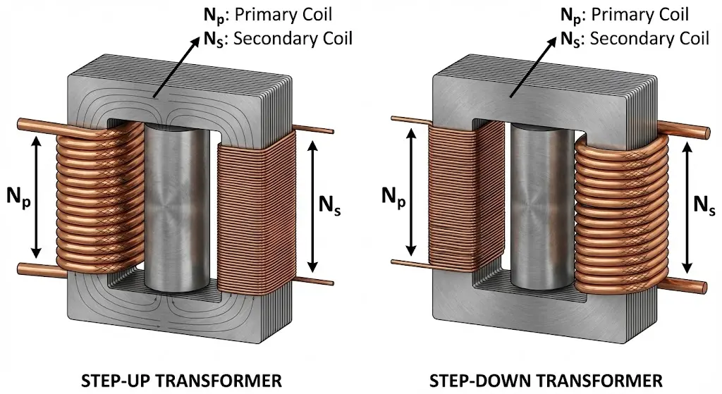
A step up transformer is engineered to deliver a secondary voltage that is significantly higher than the primary input voltage. In this configuration, the secondary winding contains a higher number of turns than the primary winding.
For a step-up transformer, the following mathematical conditions must be met:
From a construction standpoint, a step-up unit—particularly a Generator Step-Up (GSU) transformer—faces unique challenges. Because the primary side (low voltage) carries massive currents (often in the thousands of Amperes), the primary windings require specialized busbar connections and reinforced mechanical bracing to withstand the electromagnetic forces during a fault. These units are often the most critical assets in a power plant, requiring 99.99% availability and sophisticated thermal management systems.
The step down transformer is the “end-mile” hero of the electrical infrastructure. Its role is to take high-voltage transmission or medium-voltage distribution power and reduce it to levels that are safe for industrial machinery and commercial equipment.
In a step-down unit, the primary winding has more turns than the secondary winding. For a typical distribution transformer manufacturer like XBRELE, the design focus shifts toward reliability, compact footprint, and harmonic mitigation.
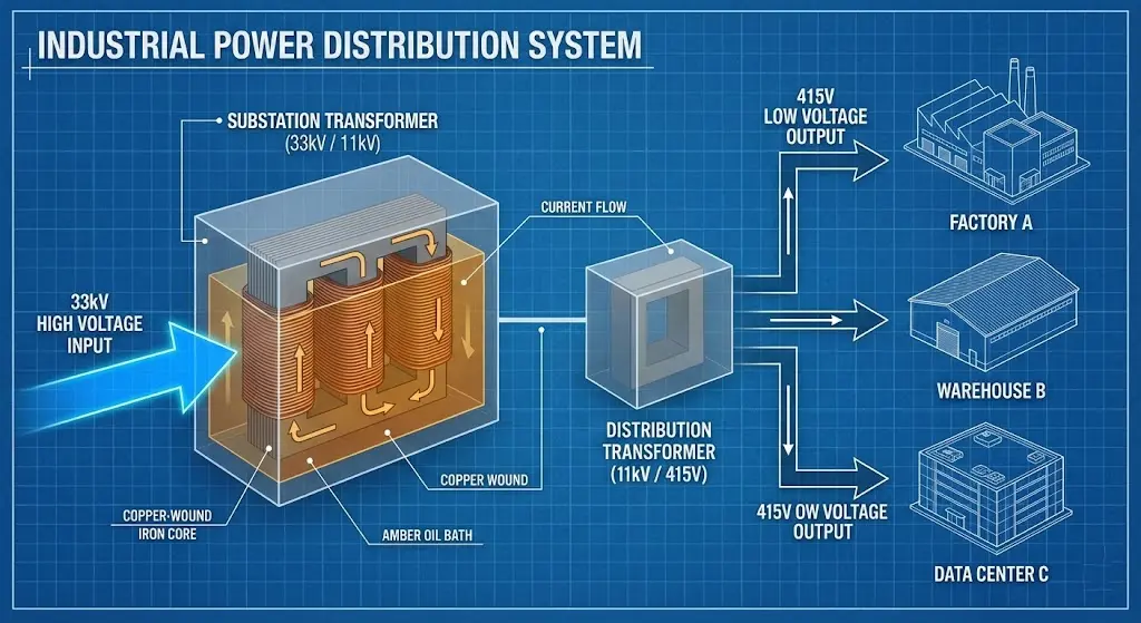
In a modern 10kV, 20kV, or 33kV network, step-down units are categorized by their placement:
As a premier manufacturer of power distribution transformers, we often see that the secondary side of these units must handle high inrush currents from industrial motors. This necessitates a robust design of the secondary windings and high-grade core steel to prevent saturation during transient events.
Understanding the operational differences is critical for procurement and system design. The table below outlines the contrast from an engineering and application perspective.
| Technical Parameter | Step-Up Transformer | Step-Down Transformer |
|---|---|---|
| Primary Goal | Minimize transmission line losses | Safe equipment operation & load isolation |
| Voltage Relationship | Secondary > Primary | Secondary < Primary |
| Turns Ratio (Ns:Np) | High (> 1) | Low (< 1) |
| Current Handling | Low current on HV side | High current on LV side |
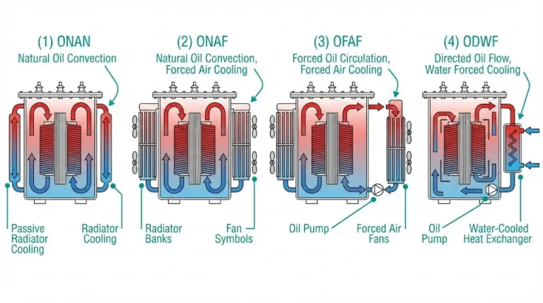
| Cooling Requirements | Complex (ONAF, OFAF) | Simpler (ONAN) or Dry Type |
| System Placement | Power Plants, Solar Farms | Substations, Factories, Buildings |
| Typical Voltages | 11kV → 220kV | 33kV → 415V; 11kV → 400V |
| Protection Focus | Over-excitation & Thermal stress | Short-circuit withstand & Harmonics |
Note: This section is intended for conceptual engineering design. Actual field installation must follow IEC 60076, local utility codes, and specific manufacturer documentation.
The fundamental relationship between voltage and turns is the cornerstone of transformer design. This ratio dictates the electromagnetic flux density and the insulation requirements.
The transformation ratio (k) is defined by:
k = Vp / Vs = Np / Ns = Is / Ip
In a step-down distribution transformer converting 11,000V to 400V, the ratio is approximately 27.5:1. This means for every Ampere on the primary, the secondary must be capable of delivering 27.5 Amperes (ignoring losses).
In three-phase systems, the wiring relationship isn’t just about the number of turns; it’s about the phase relationship between the HV and LV windings. Common configurations include:

Step-up units are the heavyweights of the grid. In high-output thermal or hydro plants, these units must maintain extremely high efficiency (often > 99.5%). At this scale, even a 0.1% loss improvement can save millions in operational costs over the transformer’s life.
Utility substations use massive step-down units to bridge the gap between regional transmission lines and city grids. These units often feature On-Load Tap Changers (OLTC) that automatically adjust the voltage as the city’s demand fluctuates. Reliability is the primary KPI here, as a failure can black out entire districts.
Inside heavy industrial sites, such as mining operations, oil immersed transformer units are often used for outdoor equipment, while dry type transformer units are preferred indoors for fire safety. These transformers step down the 10kV or 33kV supply to 400V-480V for motor control centers (MCCs).
When managing a procurement project, use this engineering checklist:
Q: Can I use a step-down transformer to step up voltage? A: Theoretically yes, but practically risky. The core may saturate, and the insulation level (BIL) might be inadequate for the higher voltage on the “new” secondary side.
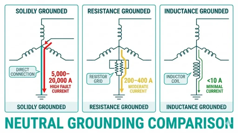
Q: Why do we need a neutral on the step-down side? A: In distribution, the neutral allows for single-phase loads (230V) and provides a path for fault currents to facilitate protection tripping.
Q: What is the most common failure mode? A: Insulation breakdown due to thermal aging or moisture ingress in oil-immersed units.
The choice between a step up transformer and a step down transformer is the most consequential decision in power system architecture. Whether it is elevating voltage at a generation site or stepping down power for a factory, these units are the silent enablers of modern industry. Success in these projects requires a partnership with an experienced distribution transformer manufacturer.
At XBRELE, our power distribution transformers are engineered for resilience. Contact our engineering desk today to discuss your specific voltage requirements.
External Reference: Transformer design and test framework for this topic is defined in the IEC 60076 power transformer standard series.
A comprehensive technical guide for EPC contractors and utility engineers. This document covers winding ratios, voltage transformation physics, and global power distribution standards (IEC 60076).
Download Transformer Engineering Guide