Need Full Specifications?
Download our 2025 Product Catalog for detailed drawings and technical parameters of all switchgear components.
Get CatalogDownload our 2025 Product Catalog for detailed drawings and technical parameters of all switchgear components.
Get CatalogDownload our 2025 Product Catalog for detailed drawings and technical parameters of all switchgear components.
Get Catalog
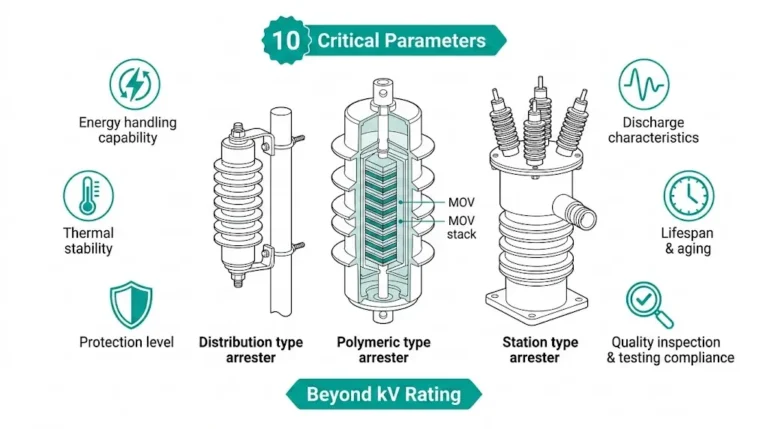
A surge arrester is a protective device that limits transient overvoltages by diverting surge current to ground while clamping voltage to levels safe for connected equipment. Unlike fuses or circuit breakers that interrupt current flow, surge arresters respond within nanoseconds and automatically reset—providing continuous protection without circuit disconnection.
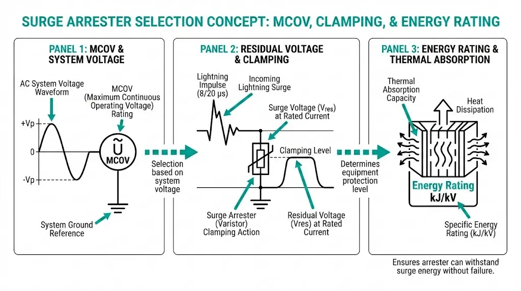
In medium-voltage distribution networks operating at 10–36 kV, metal oxide surge arresters (MOSAs) serve as the primary defense against lightning strikes and switching transients that would otherwise damage transformers, vacuum circuit breakers, and cable terminations. Proper selection depends on three interdependent parameters: Maximum Continuous Operating Voltage (MCOV), residual voltage, and energy rating. Each addresses a distinct failure mode—and neglecting any one compromises the entire protection scheme.
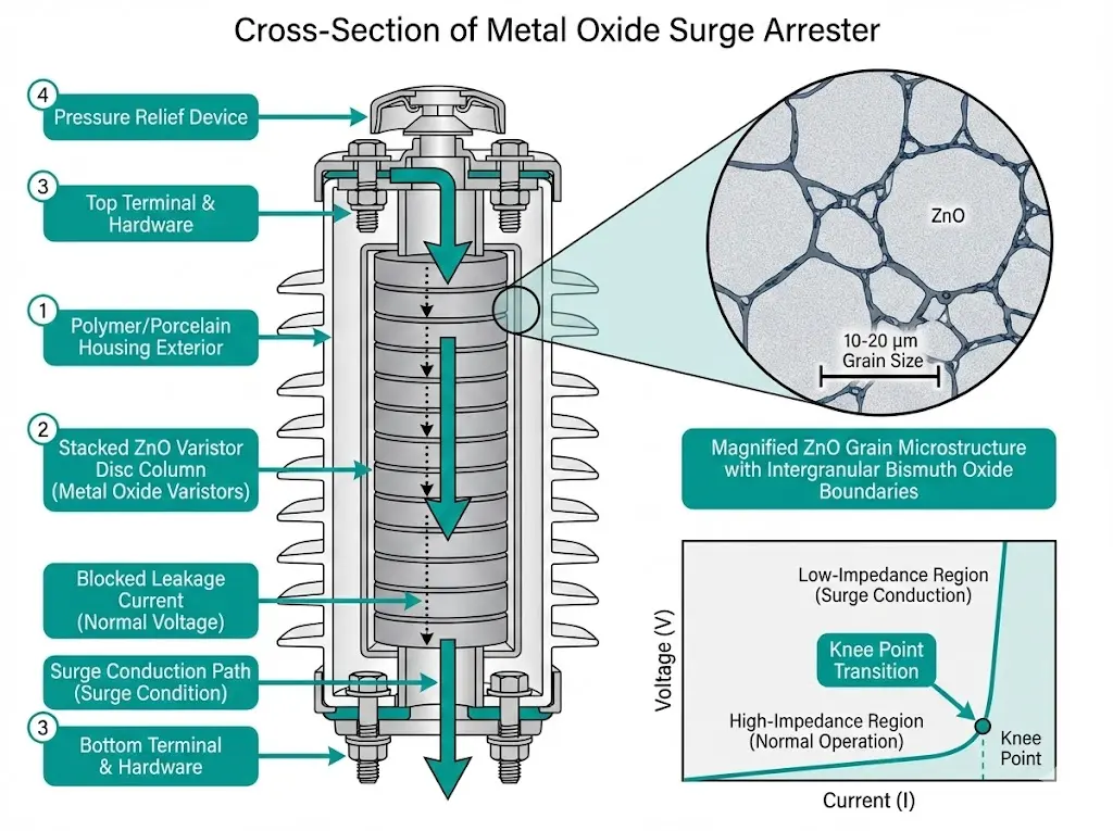
Modern surge arresters rely on zinc oxide (ZnO) varistor technology to achieve voltage-dependent resistance characteristics. The ceramic microstructure contains ZnO grains (typically 10–20 μm diameter) surrounded by thin intergranular layers of bismuth oxide and other additives. These grain boundaries function as back-to-back Schottky diodes, creating the nonlinear behavior essential for surge protection.
Under normal operating voltage, the varistor exhibits extremely high resistance—exceeding 10⁹ Ω—drawing only microampere-level leakage current (typically 0.5–2 mA for distribution-class units). When transient overvoltage exceeds the conduction threshold, quantum tunneling and avalanche breakdown occur at grain boundaries. Resistance drops by a factor of 10⁶ within nanoseconds.
The voltage-current relationship follows a power-law equation: I = k × Vα, where the nonlinearity coefficient α ranges from 25 to 50 for modern MOV materials. This extreme nonlinearity means increasing voltage by 20% can increase current flow by a factor of 105 or more.
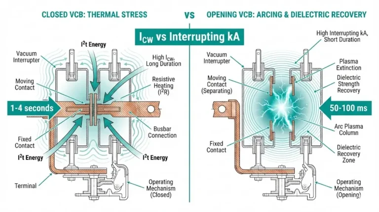
During a 10 kA lightning surge, a properly selected arrester limits voltage rise to approximately 2.5–3.5 times MCOV while conducting the full surge current. Response time measures under 25 nanoseconds—fast enough to protect equipment from steep-front lightning impulses.
The energy absorption mechanism converts electrical surge energy into heat within the ZnO matrix. Thermal rise during a typical switching surge reaches 40–80°C above ambient. If energy exceeds the arrester’s rating, thermal runaway occurs: rising temperature reduces resistance, increasing current flow and heat generation until catastrophic failure results.
MCOV defines the highest RMS voltage an arrester can withstand indefinitely without degradation. This parameter forms the first gate in surge arrester selection—get it wrong, and the arrester fails within months rather than decades.
The relationship between MCOV and system voltage depends critically on grounding configuration:
Solidly grounded systems: During single-line-to-ground faults, healthy phase voltages rise to approximately 1.0–1.05 times normal. MCOV requirement:
MCOV ≥ (Um / √3) × 1.05
Ungrounded or resonant grounded systems: Healthy phases can reach full line-to-line voltage during ground faults—potentially persisting for hours. MCOV requirement:
MCOV ≥ Um × 1.05
Where Um equals maximum system voltage (not nominal voltage—a common specification error).
| System Um (kV) | Solidly Grounded MCOV (kV) | Ungrounded MCOV (kV) |
|---|---|---|
| 12 | 7.6 | 12.7 |
| 24 | 15.3 | 25.5 |
| 36 | 22.9 | 38.0 |
| 40.5 | 25.5 | 42.5 |
Temporary overvoltage (TOV) capability links directly to MCOV selection. Load rejection, Ferranti rise on unloaded cables, or transformer energization can elevate voltage above normal levels for seconds to minutes. IEC 60099-4 specifies TOV withstand requirements: arresters must survive 1.4 × MCOV for 10 seconds without damage.

[Expert Insight: MCOV Margin in Practice]
- Field failures often trace to MCOV selected based on nominal voltage (e.g., 10 kV) rather than maximum system voltage (e.g., 12 kV)
- Ungrounded industrial systems frequently experience sustained overvoltages during ground fault hunting—specify generous MCOV margin
- Resonant grounded (Petersen coil) systems require the same MCOV as ungrounded systems
- When uncertain about grounding configuration, default to ungrounded MCOV values
Residual voltage—the voltage across arrester terminals during surge discharge—determines actual equipment protection. Two standardized waveforms characterize arrester performance:
Lightning impulse (8/20 μs): Simulates direct or nearby lightning strikes. The Lightning Impulse Protective Level (LIPL) is measured at nominal discharge currents of 5 kA, 10 kA, or 20 kA depending on arrester class.
Switching impulse (30/60 μs): Represents switching operations such as capacitor bank energization or line reclosing. The Switching Impulse Protective Level (SIPL) applies primarily to transmission-class arresters.
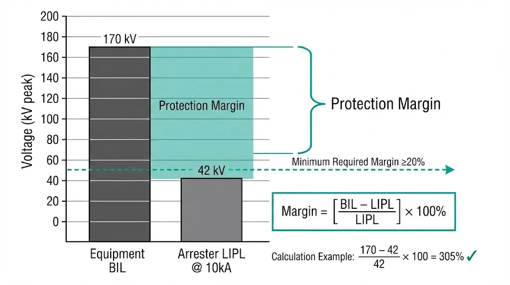
Protective level must remain below protected equipment’s Basic Insulation Level (BIL). The protection margin calculation:
Protection Margin (%) = [(BIL − Protective Level) / Protective Level] × 100
According to IEC 60099-5 (selection and application recommendations), minimum margins of 20% for lightning impulse and 15% for switching impulse ensure reliable protection accounting for arrester aging and distance effects.
| Equipment BIL (kV peak) | Maximum Acceptable LIPL (kV peak) | Resulting Margin |
|---|---|---|
| 75 | ≤60 | 25% |
| 95 | ≤76 | 25% |
| 125 | ≤100 | 25% |
| 170 | ≤136 | 25% |
Lower residual voltage provides better protection but typically requires larger physical size and higher cost. For distribution applications protecting 95 kV BIL equipment, selecting an arrester with LIPL of 70 kV (36% margin) rather than 76 kV (25% margin) may not justify the cost premium.
Energy rating quantifies how many joules the arrester can absorb without thermal failure. This parameter proves critical for applications beyond basic lightning protection—capacitor bank switching, cable energization, and systems with high lightning flash density all impose significant energy demands.
IEC 60099-4 classifies energy capability through multiple metrics:
Line discharge class (Class 1–5): Defines capability to handle transmission line discharge events. Class 2 suits most distribution applications; Class 3–4 applies to substation protection and capacitor switching.
Thermal energy rating (kJ/kV of Ur): Total energy the arrester can absorb in a defined time window without exceeding thermal stability limits.
Charge transfer rating (Coulombs): Newer classification approach capturing both impulse and long-duration current handling.
| Application | Recommended Class | Typical Energy (kJ/kV Ur) |
|---|---|---|
| MV distribution feeder | Class 2 | 2.5–4.0 |
| Substation transformer protection | Class 3 | 4.5–6.0 |
| Capacitor bank / shunt reactor | Class 3–4 | 6.0–8.0 |
| Long cable termination | Class 3 | 5.0–7.0 |
Energy absorption depends on ZnO grain size and dopant concentrations. Quality MOV materials handle specific energy of 150–200 J/cm³. Physical size directly correlates with energy capability—station-class arresters with 100 mm disc diameters absorb far more energy than distribution-class units with 40–60 mm discs.
The thermal stability test per IEC 60099-4 verifies that after rated energy injection, the arrester returns to stable leakage current levels without thermal runaway. This test simulates worst-case field conditions where multiple surges occur before the arrester fully cools.
[Expert Insight: Energy Rating Field Considerations]
- Cable-connected transformers can generate switching energies of 6–8 kJ/kV during energization—standard distribution arresters may be inadequate
- High lightning flash density regions (>8 flashes/km²/year) require upgraded energy ratings for multi-stroke events
- Capacitor bank installations impose repetitive energy stress; cumulative thermal aging accelerates failure
- When in doubt, specify one class higher than calculations suggest—the cost premium is minimal compared to replacement costs
Consider a 12 kV ungrounded industrial system protecting a 170 kV BIL oil-immersed transformer.
Step 1: Determine system maximum voltage
Um = 12 kV (not 10 kV nominal)
Step 2: Identify grounding configuration
Ungrounded system → healthy phases reach full line voltage during ground faults
Step 3: Calculate minimum MCOV
MCOV ≥ Um × 1.05 = 12 × 1.05 = 12.6 kV
Select arrester with MCOV ≥ 12.7 kV (standard rating)
Step 4: Check residual voltage
Selected arrester: LIPL at 10 kA = 42 kV peak
Step 5: Verify protection margin
Margin = [(170 − 42) / 42] × 100 = 305%
Far exceeds 20% minimum ✓
Step 6: Assess energy requirement
Standard distribution feeder, no capacitor banks, moderate lightning region
Class 2 sufficient (≥3.0 kJ/kV Ur)
Final Specification:
Arrester mounting on post insulators should maintain clearances consistent with system BIL. Lead length between arrester terminals and protected equipment affects actual protective level—keep connections under 1 meter where possible.
Laboratory ratings assume standard conditions: altitude below 1000 m, ambient temperature 20°C, clean housing surface. Real installations rarely match these assumptions.
Altitude derating: Above 1000 m, reduced air density decreases external flashover voltage by approximately 1% per 100 m. At 2000 m elevation, consider selecting the next voltage class or specifying extended creepage polymer housings.
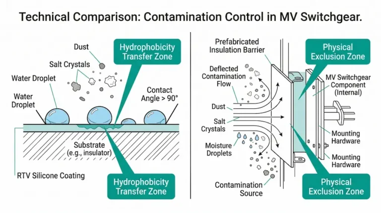
Pollution severity: IEC 60815 defines pollution classes from “very light” to “very heavy.” Contamination deposits on arrester housings reduce flashover margin. Polymer housings outperform porcelain in heavy pollution—their hydrophobic surface sheds contamination and maintains higher flashover strength. Specify creepage distance ≥25 mm/kV for heavily polluted environments.
Temperature extremes: Standard arresters operate from −40°C to +40°C ambient. Higher temperatures accelerate MOV aging; lower temperatures affect polymer housing flexibility. Verify manufacturer specifications for extreme climate installations.
Housing material selection:
Disconnector integration: Distribution arresters often include integral disconnectors that isolate failed units and provide visual indication. Useful where inspection intervals exceed one year. The disconnector activates when sustained fault current melts a fusible element following arrester failure.

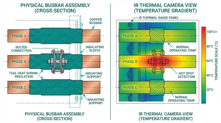
Surge arresters function within a broader insulation coordination scheme. Proper protection requires matching arrester protective levels with the insulation strength of transformers, circuit breakers, and switchgear components throughout the system.
XBRELE manufactures vacuum circuit breakers, vacuum contactors, and medium-voltage switchgear components designed for systems up to 40.5 kV. Our engineering team supports insulation coordination analysis, helping match VCB ratings and component specifications to your surge protection requirements.
Whether you’re specifying new substations or upgrading existing protection schemes, contact XBRELE for technical consultation. We provide detailed coordination data sheets and can recommend appropriate BIL ratings for equipment operating alongside your selected surge arresters.
What causes surge arrester failure even when ratings appear correct?
Most field failures trace to installation issues rather than rating errors. Excessive lead length adds voltage drop during surges—each meter of conductor contributes roughly 1 kV during steep-front impulses. Ground impedance exceeding 5 Ω elevates effective clamping voltage, reducing protection margins below safe thresholds.
How does grounding configuration affect MCOV selection?
Ungrounded and resonant grounded systems require MCOV equal to or exceeding full line-to-line voltage because healthy phases sustain elevated voltage throughout ground fault duration. Solidly grounded systems need only line-to-neutral voltage plus margin since fault clearing occurs within cycles.
Can distribution-class arresters protect substation equipment?
Distribution-class arresters (typically Class 2 energy rating) lack sufficient energy absorption for substation entrance applications where switching surges and multi-stroke lightning events impose higher thermal stress. Station-class arresters (Class 3 or higher) are generally required for transformer and bus protection.
Why do polymer-housed arresters dominate new installations?
Polymer housings offer three advantages: lighter weight reducing mechanical stress on mounting structures, superior performance in polluted environments due to hydrophobic surface properties, and non-fragmenting failure mode eliminating porcelain shrapnel hazards during catastrophic failure.
How often should surge arresters be tested or replaced?
Visual inspection annually catches obvious damage—cracked housings, disconnector operation, or burn marks. Leakage current measurement every 3–5 years provides quantitative condition assessment. Well-selected arresters in moderate environments typically achieve 20–25 years of service life; high-lightning or polluted environments may reduce this to 12–15 years.
What is the relationship between residual voltage and discharge current?
Residual voltage increases with discharge current magnitude due to MOV resistance characteristics. A 10 kA surge produces higher clamping voltage than a 5 kA surge through the same arrester. Manufacturers specify residual voltage at multiple current levels (typically 5 kA, 10 kA, 20 kA) to enable accurate coordination calculations.
Does arrester location within a substation matter?
Voltage wavefronts travel at approximately 300 m/μs, creating distance-dependent protection degradation. Equipment located more than 8–10 meters from the arrester experiences higher voltage stress due to traveling wave reflections. Each critical asset—transformers, circuit breakers, cable terminations—benefits from dedicated surge protection when physical separation exceeds these limits.