Need Full Specifications?
Download our 2025 Product Catalog for detailed drawings and technical parameters of all switchgear components.
Get CatalogDownload our 2025 Product Catalog for detailed drawings and technical parameters of all switchgear components.
Get CatalogDownload our 2025 Product Catalog for detailed drawings and technical parameters of all switchgear components.
Get Catalog
Temperature rise in power transformers determines operational loading limits, expected service life, and long-term asset reliability. The four-letter cooling codes—ONAN, ONAF, OFAF, ODWF—encode how heat moves from windings to ambient air, providing procurement engineers with critical selection criteria for matching thermal capacity to actual site conditions.
The physics centers on two loss mechanisms: no-load losses in the magnetic core and load losses in windings. These losses convert to heat that must transfer through a thermal pathway—from copper conductors through insulation paper, into transformer oil, and finally to ambient air or water. The temperature gradient across this pathway determines hotspot temperature, the single most critical parameter for cellulose insulation aging.
Cooling code selection directly influences achievable MVA ratings under identical thermal limits. An ONAN-rated transformer might achieve only 60–75% of its ONAF rating due to reduced heat dissipation without forced air assistance. Understanding this relationship prevents two costly procurement errors: under-specifying units that run hot and age prematurely, or over-specifying units with cooling capacity you never utilize.
Every oil-immersed transformer carries a four-letter cooling designation on its nameplate. These letters follow IEC 60076-2 nomenclature and encode the complete heat-transfer pathway in a compact format that determines maximum continuous loading capacity, auxiliary equipment requirements, and long-term reliability characteristics.
| Position | Describes | Letter Options | Meaning |
|---|---|---|---|
| 1st | Internal coolant type | O | Mineral oil (flash point ≤300°C) |
| K | Ester fluid (natural or synthetic) | ||
| 2nd | Internal coolant circulation | N | Natural (thermosiphon) |
| F | Forced (pump-driven) | ||
| D | Directed through specific winding ducts | ||
| 3rd | External coolant type | A | Air |
| W | Water | ||
| 4th | External coolant circulation | N | Natural convection |
| F | Forced (fans or pumps) |
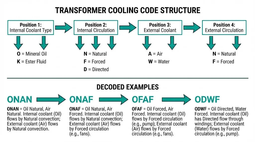
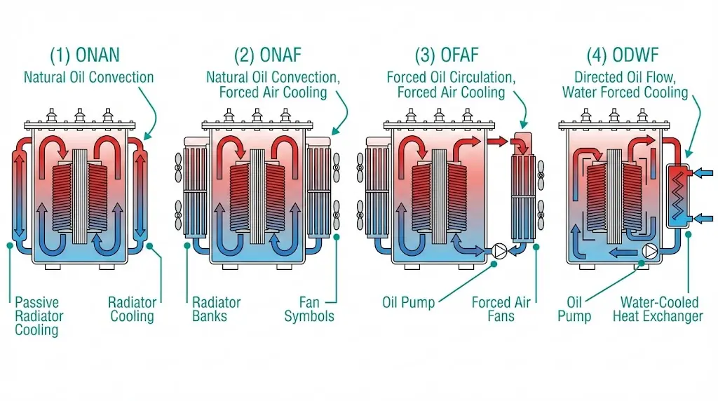
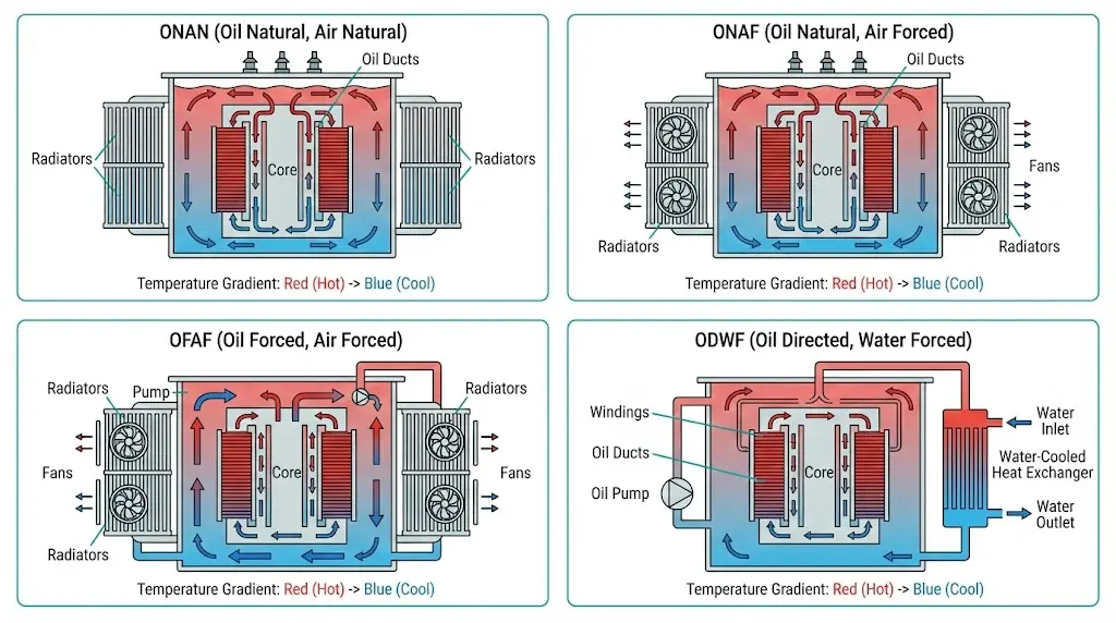
ONAN (Oil Natural, Air Natural): Mineral oil circulates by thermosiphon effect—hot oil rises, cooled oil sinks. Heat transfers to ambient through tank walls and radiators via natural convection. No pumps, no fans.
ONAF (Oil Natural, Air Forced): Same natural oil circulation, but fans force air across radiator surfaces. Forced airflow increases heat rejection capacity by 25–33% compared to ONAN operation.
OFAF (Oil Forced, Air Forced): Pumps drive oil through the transformer while fans move air across coolers. Both mechanical systems maximize heat transfer in the smallest footprint.
ODWF (Oil Directed, Water Forced): Pumps push oil through dedicated winding channels. External heat exchangers use pumped water instead of air—essential for indoor installations or contaminated atmospheres.
Natural convection in ONAN transformers relies on oil density differentials created by temperature gradients. Hot oil near windings (typically 85–95°C) rises through cooling ducts while cooler oil (60–70°C) descends from radiator surfaces. This thermosiphon effect generates flow velocities of approximately 0.1–0.3 m/s through winding channels without mechanical assistance.
Forced cooling methods enhance heat transfer coefficients significantly. Air-blast cooling in ONAF designs increases convective heat transfer from radiator surfaces by 2–3× compared to natural circulation. Water-forced systems achieve heat transfer coefficients exceeding 1,000 W/m²·K at heat exchanger surfaces, making them suitable for high-capacity units above 100 MVA.
| Cooling Class | Relative Capacity | Reliability Rank | Maintenance Burden | Typical Applications |
|---|---|---|---|---|
| ONAN | 1.0× (base) | Highest | Minimal | Rural distribution, noise-sensitive sites |
| ONAF | 1.25–1.33× | High | Low (fan service) | Urban substations, variable loads |
| OFAF | 1.5–1.67× | Moderate | Medium (pumps + fans) | Large power transformers, space-constrained |
| ODWF | 1.67–2.0× | Lower | High (water treatment) | Indoor installations, extreme ambients |
The dual-rating convention deserves attention: a nameplate showing “10/12.5 MVA ONAN/ONAF” means 10 MVA continuous with fans off, 12.5 MVA with fans running. This flexibility allows operators to match cooling intensity to actual load conditions.
For comprehensive transformer solutions with various cooling configurations, see our power distribution transformer overview.
[Expert Insight: Cooling Class Selection]
- Field data from 80+ substation projects shows ONAN/ONAF dual-rated units provide optimal flexibility for loads varying 40–100% of nameplate
- Fan staging at 70% and 100% load thresholds balances energy consumption against thermal margin
- OFAF specifications add 15–25% to capital cost—justify only when space constraints or load density demands it
- Water-cooled units require ongoing water treatment programs; budget $3,000–8,000 annually for chemistry management
The thermal resistance pathway follows a predictable sequence: heat flows from the winding conductor (copper at ~75°C rise) → through paper insulation (thermal conductivity ≈ 0.13 W/m·K) → into transformer oil (viscosity-dependent convection) → through the tank wall → to external cooling media. Each interface introduces thermal resistance that cooling systems must overcome.
| Parameter | IEC 60076-2 Limit | IEEE C57.12.00 Limit |
|---|---|---|
| Top-oil temperature rise | 60 K | 65 K |
| Average winding rise | 65 K | 65 K |
| Hot-spot rise (winding) | 78 K | 80 K |
| Maximum ambient (for rating) | 40°C | 30°C average, 40°C max |
The hottest spot temperature typically exceeds average winding temperature by 13–23 K, depending on winding geometry and oil circulation efficiency. This differential critically influences insulation aging according to the Arrhenius equation.
Every 6–8 K increase above rated hotspot temperature approximately doubles the insulation degradation rate. This exponential relationship makes hot-spot control—not average temperature control—the true determinant of transformer longevity.
| Hot-Spot Temperature | Relative Aging Rate | Approximate Life |
|---|---|---|
| 98°C | 1.0× (reference) | ~180,000 hours |
| 104°C | 2.0× | ~90,000 hours |
| 110°C | 4.0× | ~45,000 hours |
| 116°C | 8.0× | ~22,500 hours |
For procurement specifications, request both guaranteed temperature rise values and actual factory test results. Units achieving 52–55 K top-oil rise under test conditions provide superior margin for overload events compared to units tested at exactly 60 K limits.
Understanding thermal coordination between transformers and upstream protection is essential. Our guide to vacuum circuit breaker working principles explains complementary protection considerations.
Most distribution transformers don’t operate continuously at rated load. Variable loading creates thermal cycles where periods of light load allow recovery from peak stress events. IEC 60076-7 codifies acceptable overload practices.
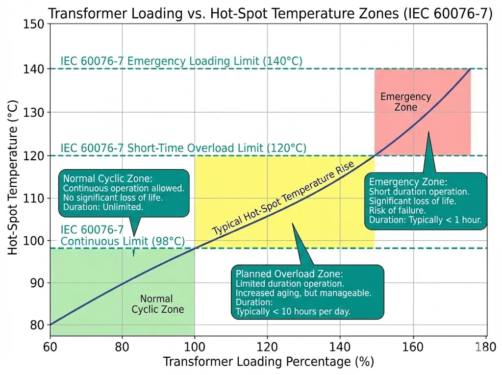
| Loading Type | Duration | Typical Limit | Hot-Spot Constraint |
|---|---|---|---|
| Normal cyclic | Indefinite | 100% nameplate | 98°C continuous |
| Planned overload | Hours | 120–150% | 120°C peak |
| Emergency overload | <30 minutes | 150–180% | 140°C absolute max |
These capabilities assume the transformer wasn’t already running hot, cooling systems operate correctly, and subsequent recovery periods at reduced load follow the overload event.
Nameplate ratings assume specific ambient conditions. When actual ambient exceeds assumptions:
High-altitude installations in mountainous regions face compounded challenges—thinner air reduces both convective cooling effectiveness and dielectric strength. A 2,500 m installation may require 6% capacity derating plus enhanced BIL ratings.
Each cooling class carries distinct reliability characteristics that directly impact lifecycle costs and operational risk.
ONAN Failure Modes:
ONAF Additional Failures:
OFAF/ODWF Additional Failures:
Reliability ranking (highest to lowest): ONAN > ONAF > OFAF > ODWF
For critical applications, specify N+1 fan banks (one bank can fail without immediate derating), redundant oil pumps for OFAF/ODAF, and independent control power for cooling auxiliaries. These redundancy features integrate with broader substation protection schemes—see our switchgear component integration page for system-level coordination.
[Expert Insight: Field Reliability Observations]
- Fan motors in coastal environments typically last 6–8 years versus 12–15 years inland due to salt contamination
- Oil pump seal failures often precede detectable oil leaks by 6–12 months; vibration monitoring catches early degradation
- Temperature sensor recalibration every 3–5 years prevents fan staging errors that silently reduce transformer capacity
- Control power loss during grid disturbances disables cooling precisely when transformers need it most—specify UPS backup
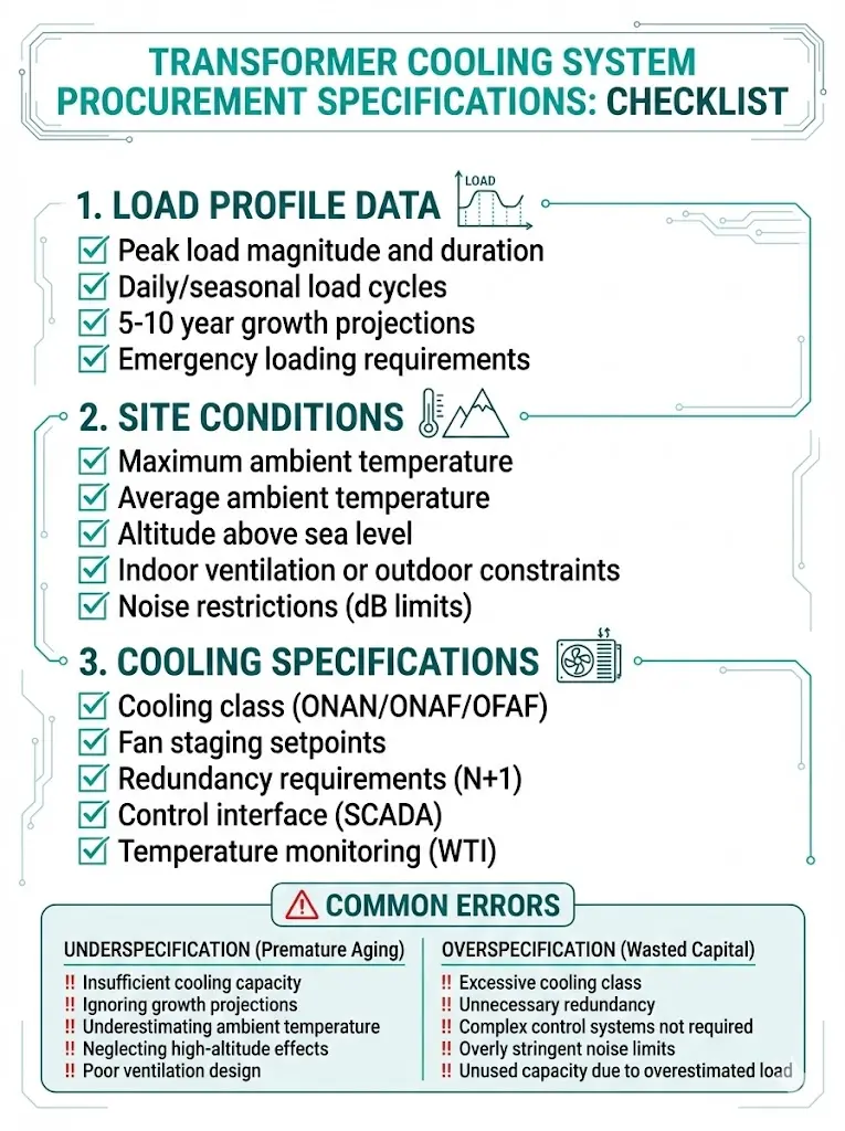
Accurate load characterization prevents both under- and over-specification:
| Specification Item | Guidance |
|---|---|
| Cooling class | Specify primary and secondary (e.g., ONAN/ONAF) |
| Fan staging | Number of stages, temperature setpoints (typically 70%, 100% load) |
| Redundancy | N+1 fans for critical loads, redundant pumps if OFAF |
| Noise limits | Specify dB(A) at defined distance |
| Control interface | Local indication, remote alarming, SCADA points |
| Temperature monitoring | Top-oil indicator (standard), WTI with hot-spot simulation (recommended) |
Underspecification consequences: Premature insulation aging, operational loading restrictions, warranty disputes over thermal performance.
Overspecification consequences: 15–25% unnecessary capital expenditure, ongoing maintenance burden for unused capacity.
Cost impact guidance: ONAN→ONAF adds 5–10% to transformer cost. ONAF→OFAF adds 15–25%. Match cooling class to the load profile you actually have, not worst-case assumptions.
For coordinated procurement of transformers with upstream switching equipment, our vacuum circuit breaker platform overview outlines integrated specification approaches.
When loading growth exceeds original design assumptions, systematic thermal assessment guides upgrade decisions.
Visual Inspection:
Operational Verification:
Temperature Trending:
Add fan stages: Convert ONAN to ONAF by adding radiator-mounted fans. Requires adequate radiator surface area and control system upgrade. Cost: $8,000–25,000 depending on unit size.
Add radiator banks: Increase surface area for heat rejection. Limited by tank connection points and foundation structural capacity.
Operational load management: Stage loads across multiple transformers, implement demand response, or accept reduced peak capacity as lowest-cost alternative.
XBRELE manufactures distribution transformers with cooling configurations matched to your actual operating requirements—not oversized systems that waste capital or undersized units that limit operational flexibility.
Available cooling options: ONAN, ONAF, and ONAN/ONAF dual-rated configurations across our distribution transformer range.
Engineering support: Our applications team reviews load profile data, site conditions, and lifecycle cost objectives to recommend appropriate cooling class specifications before quotation.
Factory verification: All units undergo temperature rise testing per IEC 60076-2 requirements, with certified test reports documenting actual thermal performance against guaranteed values.
Request a consultation to review your transformer cooling requirements, or submit your specification for competitive quotation with engineering recommendations included.
Q: What is the difference between ONAN and ONAF transformer cooling?
A: ONAN relies entirely on natural oil circulation and passive air cooling with no mechanical components, while ONAF adds radiator-mounted fans that increase heat rejection capacity by 25–33% when energized.
Q: How much does ambient temperature affect transformer loading capacity?
A: Each degree Celsius above the 30°C design ambient typically requires 1.5% load reduction to maintain safe operating temperatures; a 40°C ambient may limit continuous operation to approximately 85% of nameplate rating.
Q: Can transformers operate above nameplate rating during emergencies?
A: Short-duration overloads up to 150–180% are generally acceptable for periods under 30 minutes, provided the unit was not already thermally stressed and a recovery period at reduced load follows.
Q: Which cooling class offers the highest reliability?
A: ONAN provides the highest reliability because it contains no rotating equipment—every added component (fans in ONAF, pumps in OFAF) introduces additional failure modes requiring maintenance.
Q: What temperature actually determines transformer insulation life?
A: The winding hot-spot temperature governs aging rate, typically running 13–23 K higher than average winding temperature depending on design; this localized peak—not bulk oil temperature—drives cellulose degradation.
Q: How much additional cost does upgrading from ONAN to ONAF add?
A: Expect 5–10% cost increase for ONAF capability over equivalent ONAN rating; moving to OFAF adds 15–25% due to pumps, enhanced controls, and redundancy requirements.
Q: Can existing ONAN transformers be retrofitted with forced cooling?
A: Retrofit fan addition is feasible if existing radiators have sufficient surface area, typically costing $8,000–25,000 including controls; pump retrofits for OFAF conversion are rarely cost-effective compared to replacement.
For detailed loading calculations and hot-spot temperature modeling methodologies, refer to IEEE C57.91 (Guide for Loading Mineral-Oil-Immersed Transformers) available through the IEEE Standards Association.
This guide provides engineering guidance for transformer cooling specification and procurement. Specific applications require evaluation by qualified engineers considering local conditions, applicable codes, and utility interconnection requirements.