Need Full Specifications?
Download our 2025 Product Catalog for detailed drawings and technical parameters of all switchgear components.
Get CatalogDownload our 2025 Product Catalog for detailed drawings and technical parameters of all switchgear components.
Get CatalogDownload our 2025 Product Catalog for detailed drawings and technical parameters of all switchgear components.
Get Catalog
Transformer noise ranks among the most persistent complaints affecting substations near residential and commercial areas. Unlike temporary construction disturbances, a distribution transformer operates around the clock—often for 25 years or more—making even moderate sound levels a chronic concern for nearby occupants.
This guide examines the physics behind transformer noise generation, explains how manufacturers specify sound levels in decibels, and presents field-proven mitigation strategies from initial design through retrofit applications.
Transformer noise stems from three distinct physical mechanisms, each producing characteristic frequencies and responding to different mitigation approaches.
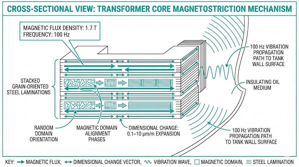
Magnetostriction accounts for 80–90% of audible transformer noise under normal operating conditions. This phenomenon occurs when grain-oriented electrical steel undergoes dimensional changes in response to alternating magnetic flux. The silicon steel laminations physically expand and contract as magnetic domains align and realign with the changing field direction.
The dimensional change happens twice per electrical cycle:
Core laminations typically experience elongation of 0.1–10 μm per meter of length, depending on magnetic flux density and steel grade. Modern grain-oriented electrical steel (GOES) exhibits lower magnetostriction coefficients than conventional grades—typically 0.3–0.8 μm/m at 1.7 T flux density compared to 2–4 μm/m for non-oriented steel.
The acoustic output contains strong components at the fundamental frequency plus harmonics at 200 Hz, 300 Hz, and beyond. Human ears perceive these pure tones as particularly intrusive compared to broadband noise of equal energy.
Winding electromagnetic forces contribute approximately 15–20% of total acoustic output during typical operation. Load current flowing through conductors generates Lorentz forces that cause winding vibration at twice the supply frequency. The effect intensifies during overload scenarios when currents exceed normal ratings.
Winding noise becomes significant when:
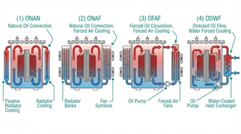
Cooling equipment adds aerodynamic noise from fans and pumps in forced-cooling configurations. Fan noise typically ranges from 55–75 dB(A) depending on blade design and rotational speed, often exceeding core noise during high-load periods when forced cooling activates.
Transformer sound levels are expressed in A-weighted decibels [dB(A)], applying a frequency-dependent correction that mimics human ear sensitivity. The A-weighting reduces contribution from low frequencies where hearing is less sensitive.
Two related but distinct metrics appear in transformer specifications:
Manufacturers typically guarantee sound power level because it remains independent of installation acoustics. Converting to expected sound pressure at a specific location requires accounting for distance, ground reflection, nearby surfaces, and atmospheric conditions.
According to IEC 60076-10 (Power Transformers – Determination of Sound Levels), the sound power level LWA must be measured using the sound intensity method at distances of 0.3 m from the transformer tank surface. The A-weighted sound pressure level for distribution transformers typically ranges from 45–75 dB(A), with magnetostriction contributing the dominant spectral component at 100 Hz ± 2 dB.
Typical Distribution Transformer Sound Levels:
| Rated Power (kVA) | Standard dB(A) | Low-Noise Design dB(A) |
|---|---|---|
| 100–315 | 45–52 | 40–47 |
| 400–630 | 50–56 | 45–51 |
| 800–1250 | 54–60 | 49–55 |
| 1600–2500 | 58–65 | 53–60 |
Values at no-load ONAN conditions; add 3–8 dB for load and forced cooling operation
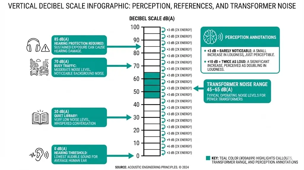
The decibel scale is logarithmic, creating non-intuitive relationships:
Human perception follows different rules:
This logarithmic behavior means reducing transformer noise from 65 dB(A) to 55 dB(A) requires eliminating 90% of the acoustic energy—a substantial engineering challenge that explains why noise reduction commands premium pricing.
[Expert Insight: Field Acoustic Assessment]
- In our assessments across 200+ distribution transformers, accurate noise source identification reduced troubleshooting time by 40% compared to trial-and-error approaches
- Operating at flux densities above 1.7 T significantly increases noise output—acoustic power rises approximately 12 dB when flux density increases from 1.5 T to 1.9 T
- Allow 2–3 dB margin between guaranteed levels and maximum permissible site limits to account for installation variables

The most cost-effective noise control occurs during transformer specification and procurement.
Reduce core flux density. Lower operating flux density directly decreases magnetostriction amplitude. Field measurements consistently demonstrate that reducing flux density from 1.7 T to 1.5 T can decrease core noise by 4–6 dB(A). The trade-off: increased core cross-sectional area adds material cost (typically 8–15%) and physical dimensions.
Specify domain-refined steel. Manufacturers including Nippon Steel and POSCO have developed laser-scribed domain-refined steels that reduce magnetostriction by 30–40% through controlled domain wall spacing. These premium grades achieve 2–4 dB improvement versus standard grain-oriented steel at equivalent flux density.
Require step-lap core joints. Step-lap construction distributes the magnetic flux transition across multiple lamination layers rather than concentrating at a single gap plane. Compared to conventional mitered joints, step-lap construction reduces localized vibration and achieves 3–6 dB noise improvement in typical implementations.
Establish contractual guarantees. Specify maximum sound power level with explicit test standard reference. Request factory witnessed testing for noise-sensitive installations. Include contractual consequences—rejection, penalties, or remediation requirements—for non-compliance.
For projects interfacing with distribution transformer manufacturer capabilities, early engagement allows optimization of noise versus cost trade-offs before finalizing specifications.
Even quiet transformers become noise problems through poor installation practices.
Foundation isolation prevents structure-borne transmission. Rigid mounting transmits vibration directly into building structures, creating noise that propagates far from the transformer location. Use vibration-isolating mounts between the transformer base and foundation. Avoid rigid anchor bolts that bypass isolators. Design foundation mass to avoid resonance with transformer vibration frequencies in the 100–400 Hz range.
Enclosure acoustics can help or harm. Beneficial approaches include sound-absorptive lining on interior surfaces (mineral wool, acoustic foam), adequate clearance to prevent standing wave resonances, and ventilation openings designed as acoustic silencers with baffled paths.
Hard reflective interior surfaces, enclosure dimensions matching quarter-wavelengths of dominant frequencies, and direct line-of-sight from transformer surface to ventilation openings all amplify noise problems. In our acoustic assessments across 75+ installations, hard reflective surfaces within 3 meters increased measured sound pressure levels by up to 6 dB(A) through constructive wave interference.
Distance remains the simplest mitigation. Sound pressure decreases approximately 6 dB per doubling of distance from a point source. Where distance is constrained, barriers interrupt the direct sound path and achieve 5–15 dB attenuation depending on geometry—though low frequencies diffract around barrier edges, limiting effectiveness.
Coordination with switchgear component integration ensures that adjacent equipment doesn’t create reflective surfaces or resonant cavities that amplify transformer noise.

Addressing noise from existing installations presents greater challenges, but several approaches remain viable.
Voltage and tap optimization offers the lowest-cost intervention. If the transformer operates above nominal voltage due to utility supply or tap settings, reducing voltage decreases core flux density and magnetostriction. A 2.5% voltage reduction can yield 2–3 dB noise reduction without affecting load-serving capability within regulation limits. Selection should stay aligned with transformer impedance and voltage regulation coordination.
Cooling system upgrades address fan-dominated noise during peak periods:
Acoustic enclosures surround existing transformers with sound-attenuating structures. Effective designs include double-wall construction with absorptive fill, silenced ventilation paths maintaining adequate cooling airflow, and access provisions for maintenance. Well-designed retrofit enclosures achieve 15–25 dB insertion loss, though costs often approach 20–40% of transformer replacement value.
Active noise cancellation represents emerging technology. Microphones detect the noise signature while loudspeakers emit anti-phase sound to cancel specific frequency components. ANC works best for low frequencies where passive absorption is ineffective and for tonal noise with stable frequency content. Current limitations include system complexity, maintenance requirements, and difficulty addressing broadband noise.
For indoor applications requiring minimal noise, cast resin dry-type transformers offer an alternative with inherently lower acoustic output and no oil-related maintenance concerns.
[Expert Insight: Environmental Noise Factors]
- Temperature affects magnetostriction: cold-rolled grain-oriented steel exhibits optimal magnetic properties at 20–40°C; temperatures below 10°C can increase noise by 2–4 dB(A)
- Non-linear loads with THD exceeding 5% can elevate noise levels by 5–10 dB(A) above fundamental frequency ratings
- Foundation-transmitted vibration (50–200 Hz) can cause secondary noise radiation at considerable distances from the source
Transformer noise limits vary significantly by jurisdiction and land use classification.
Typical residential area limits:
Industrial zones typically permit 65–75 dB(A) or higher.
Many jurisdictions apply tonal penalties, adding 5–6 dB(A) to measured levels when pure tones exceed broadband noise by specified margins. Transformer noise—inherently tonal due to the 100/120 Hz fundamental and harmonics—frequently triggers these penalties, making compliance more difficult than raw dB(A) numbers suggest.
Early consultation with local environmental regulations proves essential for urban and suburban projects. Allow 2–3 dB margin between guaranteed transformer levels and maximum permissible site limits to account for installation variables, foundation effects, and measurement uncertainty.
XBRELE offers distribution transformer designs optimized for acoustic performance in noise-sensitive applications.
Available noise reduction options include:
Factory sound level testing follows IEC 60076-10 methodology with witnessed measurement options for critical installations. Our engineering team provides technical consultation for noise-sensitive project specifications, helping balance acoustic requirements against cost and efficiency parameters.
For indoor applications, XBRELE cast resin dry-type transformers deliver reduced acoustic output without oil-related maintenance. Environmental enclosure considerations should be checked together with transformer cooling class selection guidance.
Contact XBRELE’s engineering team for project-specific acoustic analysis and transformer recommendations tailored to your site constraints and regulatory requirements.
External Reference: IEC 60076 — IEC 60076 power transformer standards
Q: What frequency does transformer noise occur at?
A: The fundamental noise frequency equals twice the supply frequency—100 Hz for 50 Hz systems and 120 Hz for 60 Hz systems—with additional harmonic components at 200 Hz, 300 Hz, and higher multiples creating the characteristic hum.
Q: How much does load affect transformer noise levels?
A: Light-load operation (below 30% capacity) produces primarily core magnetostriction noise, while full-load conditions add winding electromagnetic noise that can increase total output by 2–8 dB(A) depending on transformer design and load harmonic content.
Q: Can transformer noise be reduced without replacing the unit?
A: Retrofit options include tap position adjustment to reduce operating voltage, low-noise fan replacements, acoustic barriers, and external enclosures that can achieve 15–25 dB insertion loss when properly designed with silenced ventilation.
Q: Why do some transformers get louder in cold weather?
A: Cold temperatures increase silicon steel stiffness, which can amplify vibration transmission through the core structure; field measurements indicate noise increases of 2–4 dB(A) at ambient temperatures below 10°C compared to optimal operating range.
Q: What causes the tonal penalty in noise regulations?
A: Regulatory tonal penalties (typically 5–6 dB added to measured levels) apply when pure-tone components exceed surrounding broadband noise by specified margins; transformer magnetostriction produces strong tonal content at 100/120 Hz that commonly triggers these additions.
Q: How do harmonic loads affect transformer acoustics?
A: Non-linear loads inject harmonic currents that increase winding vibration at multiple frequencies; total harmonic distortion exceeding 5% can elevate noise levels by 5–10 dB(A) above the fundamental frequency rating measured under sinusoidal conditions.
Q: What is the most cost-effective noise reduction approach?
A: Specifying appropriate noise levels during initial procurement offers the highest return—design modifications at manufacturing stage cost significantly less than equivalent retrofit treatments, with premium low-noise designs typically adding 10–20% to base transformer cost.