Need Full Specifications?
Download our 2025 Product Catalog for detailed drawings and technical parameters of all switchgear components.
Get CatalogDownload our 2025 Product Catalog for detailed drawings and technical parameters of all switchgear components.
Get CatalogDownload our 2025 Product Catalog for detailed drawings and technical parameters of all switchgear components.
Get Catalog
A distribution transformer leaves the factory as a tested, certified asset. What happens between dispatch and first energization often determines whether that certification holds value.
Field data from commissioning teams reveals a consistent pattern: 15–20% of early transformer failures originate not from design flaws or manufacturing defects, but from shipping damage, improper storage, or installation shortcuts. These failures carry costs beyond the unit itself—project delays, emergency procurement, contractor disputes, and warranty complications that drain resources for months.
This guide addresses the non-test aspects of transformer pre-energization. The checklist framework targets distribution transformers rated 10 kV to 35 kV, spanning 100 kVA to 2500 kVA—the workhorses of industrial facilities, commercial buildings, and utility distribution networks. Each phase builds readiness for the electrical testing that follows. Skip a step, and testing results become unreliable. Execute thoroughly, and commissioning proceeds without surprises.
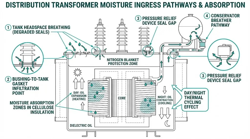
Moisture ingress represents the primary threat to transformer insulation integrity during pre-energization phases. In field assessments across 80+ utility substations, transformers stored improperly for periods exceeding 6 months consistently show elevated moisture content in oil samples—often reaching 25–35 ppm compared to the acceptable threshold of ≤10 ppm for new equipment.
The cellulose-based insulation paper wrapping transformer windings acts as a hygroscopic material with significant moisture affinity. At typical ambient conditions of 25°C and 60% relative humidity, kraft paper reaches equilibrium moisture content of approximately 6–8% by weight. This moisture absorption accelerates dielectric degradation through hydrolysis, reducing both the degree of polymerization and mechanical strength of the insulation system.
During shipping, thermal cycling creates the most problematic moisture pathway. Temperature differentials between day and night—often spanning 15–25°C—cause the transformer tank headspace to undergo breathing cycles. Atmospheric moisture enters through inadequate seals during cooling periods when internal pressure drops below ambient. Maintaining positive nitrogen pressure of 20–35 kPa in sealed tanks prevents this infiltration mechanism.
Mechanical stress compounds moisture concerns. Transit vibration frequencies typically range from 5–200 Hz, which can loosen core clamping structures and shift winding positions. Impact damage manifests in three primary categories: winding displacement detectable through transfer function analysis, gasket compression set from thermal cycling, and contamination ingress through improperly sealed pressure relief devices. CIGRE Technical Brochure 445 documents that 12% of transformer failures within the first year correlate with inadequate pre-energization verification procedures.
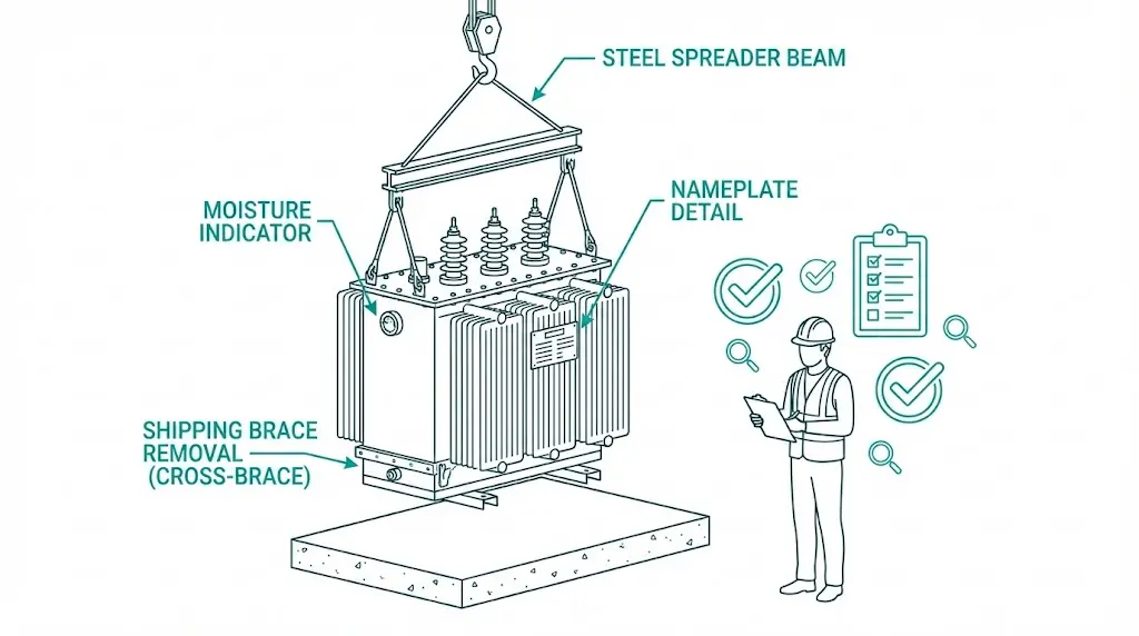
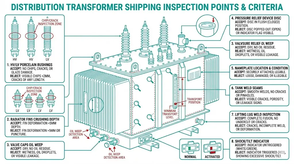
The moment a transformer arrives, inspection begins—while the unit remains on the transport vehicle. This sequence matters because unloading can mask or worsen existing damage.
Pre-unloading assessment:
Post-unloading component inspection:
| Component | Inspection Point | Accept/Reject Criteria |
|---|---|---|
| HV/LV Bushings | Porcelain surface | No chips, cracks, or glaze damage |
| Radiators/Fins | Physical alignment | No crushing >5mm depth |
| Valves | Cap presence | All caps installed, no oil weep |
| Pressure relief device | Disc position | Seated, no rupture indication |
| Nameplate | Legibility | Matches purchase order specifications |
| Tank seams | Weld appearance | No visible cracks or seepage |
| Lifting lugs | Weld integrity | No cracks or deformation |
For oil-filled units, check the magnetic oil level gauge—pointer should indicate within the “cold” or “transport” zone. Examine the Buchholz relay collection chamber for accumulated gas. Dry-type transformers ship with humidity indicator cards visible through inspection windows. Blue indicates acceptable moisture levels below 30% RH. Pink signals moisture ingress requiring remediation before energization.
Photographic documentation proves essential for freight claims and manufacturer warranty discussions. Include shipping labels and any indicator readings in the photo set. For comprehensive specifications on distribution transformer construction, refer to XBRELE’s distribution transformer technical resources.
[Expert Insight: Field Observations on Shipping Damage]
- Porcelain bushing micro-cracks often appear only under oblique lighting—inspect at multiple angles
- Oil weeping at valve stems frequently indicates O-ring damage from temperature cycling during transit
- Shock indicators positioned on transformer base detect vertical impacts; side-mounted units catch lateral forces—check both locations
- Nameplate discrepancies between shipped unit and purchase order cause more commissioning delays than actual defects
Project timelines slip. Substations aren’t ready. Permits stall. When a transformer must wait weeks or months before installation, storage conditions directly impact whether it energizes successfully or requires expensive reconditioning.
Indoor storage thresholds:
Outdoor storage demands active mitigation. This approach should remain temporary—ideally under 30 days.
Elevate transformers on concrete blocks or timber cribbing, minimum 150mm above grade. Standing water contact accelerates tank corrosion within days. Use industrial-grade tarps secured against wind lift, but leave bottom edges partially open—fully sealed enclosures trap condensation. Factory-installed bushing caps must remain in place throughout storage.
| Storage Type | Max Duration | Humidity Limit | Key Requirements |
|---|---|---|---|
| Indoor (climate-controlled) | 12+ months | <60% RH | Monthly visual inspection |
| Indoor (uncontrolled) | 6 months | <70% RH | Desiccant monitoring, breather checks |
| Outdoor (protected) | 30 days | N/A | Elevated, tarped, weekly pressure checks |
Nitrogen blanket monitoring applies to units over 1000 kVA. Check pressure gauge weekly. Acceptable range typically falls between 0.2–0.5 bar positive pressure, though manufacturer specifications vary. If pressure drops below threshold, contact the manufacturer before attempting to recharge—incorrect nitrogen purity or moisture content introduces contamination.
Silica gel breathers on conservator-type transformers should display blue coloration indicating moisture content below 35% saturation. When gel transitions to pink, immediate replacement prevents moisture transfer to the oil preservation system. The IEC 60076 series provides foundational guidance on transformer handling and storage requirements.
Proper site readiness eliminates the scramble that leads to installation compromises. Complete these items before the transformer delivery date.
Foundation specifications by rating:
| Rating (kVA) | Weight Range (kg) | Pad Thickness | Pad Dimensions |
|---|---|---|---|
| 100–315 | 800–1,800 | 150mm | 1.5m × 1.5m |
| 500–1,000 | 2,000–4,000 | 200mm | 2.0m × 2.0m |
| 1,250–2,500 | 4,500–8,000 | 250mm | 2.5m × 3.0m |
Level tolerance must not exceed ±5mm across the pad surface. Verify anchor bolt locations against manufacturer drawings before concrete pour. Allow minimum 7 days curing time under normal conditions. Oil containment provisions—either integral bund walls or connection to oil-water separator systems—require completion before transformer placement.
Rigging demands precision. Use only designated lifting lugs. Never lift by bushings, radiator brackets, or valve flanges under any circumstances. Units over 2,000 kg require spreader beams to maintain proper sling angles. Maintain strictly vertical lift; side-loading the lugs risks weld failure.
Lower slowly onto the foundation—no dropping, even from 50mm height. Align base holes with anchor bolts before full weight transfer. Check level in two perpendicular directions. Install anchor bolt nuts hand-tight initially, then final torque in cross-pattern sequence per manufacturer specification.
Bushing connection sequence:

Understanding the broader switchgear ecosystem helps contextualize transformer integration. The principles of vacuum circuit breaker operation demonstrate similar attention to sealed system integrity during installation.
[Expert Insight: Installation Lessons from 200+ Commissioning Projects]
- Uneven foundations cause oil level gauge errors that persist throughout the transformer’s service life—verify level before and after anchor bolt torquing
- Bushing connection torque values differ between aluminum and copper terminals; always reference the specific nameplate material
- Cable termination stress on bushings causes more porcelain failures than shipping damage—use proper cable support within 300mm of connection point
- Document the as-installed tap changer position photographically; operators frequently dispute initial settings during load balancing
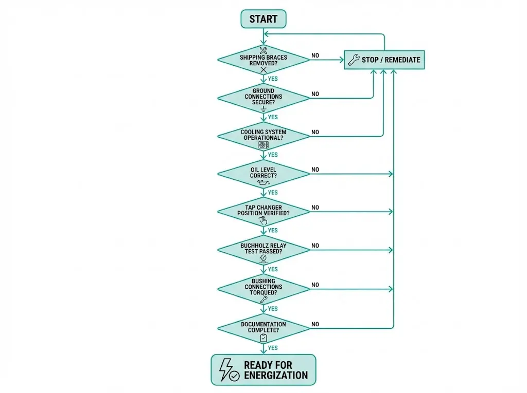
Before applying voltage, walk through this confirmation sequence. Each item represents a failure mode observed in field commissioning.
Go/No-Go verification:
Documentation package assembly supports commissioning sign-off and future maintenance:
This documentation becomes part of the asset’s permanent file. During warranty claims or failure investigations, incomplete records shift burden of proof to the owner. For guidance on related switchgear component integration, XBRELE’s component manufacturing expertise provides additional technical resources.
Field experience reveals recurring errors that systematic checklists aim to prevent:
| Mistake | Consequence | Prevention |
|---|---|---|
| Shipping braces left installed | Core/winding damage on thermal expansion | Verify removal during installation—check inside tank if accessible |
| Bushing caps removed early | Moisture and debris contamination | Remove only at connection time, never days before |
| Pink humidity indicator ignored | Insulation breakdown under load, often within hours | Mandatory remediation before energization |
| Uneven foundation | Tank stress, oil gauge errors, cooling inefficiency | Level verification before and after placement |
| Generic torque values applied | Loose connections causing heating, or porcelain cracks | Use manufacturer specifications exclusively |
| Nitrogen blanket not monitored | Loss of inert atmosphere, moisture ingress | Weekly pressure gauge checks during storage |
The pre-energization inspection scope differs fundamentally from factory acceptance testing. Factory tests verify design compliance under controlled conditions. Site inspections confirm that shipping and storage have not compromised operational readiness. This distinction requires personnel to focus on condition changes rather than absolute performance metrics.
XBRELE engineers distribution transformers for reliable field deployment across industrial, commercial, and utility applications. Factory testing protocols and comprehensive documentation packages support smooth commissioning workflows.
Technical support extends beyond equipment delivery. Pre-energization questions, installation guidance, and troubleshooting assistance help commissioning teams execute with confidence.
Explore distribution transformer specifications and application engineering support for your next project.
Q: How long can a transformer remain in outdoor storage before requiring reconditioning?
A: Protected outdoor storage should not exceed 30 days; beyond this period, moisture ingress risk increases significantly and insulation testing typically reveals elevated moisture content requiring oil processing or drying procedures.
Q: What does a pink humidity indicator mean on a dry-type transformer?
A: Pink coloration indicates relative humidity inside the enclosure has exceeded 30%, signaling moisture ingress that compromises insulation integrity—drying procedures must be completed before energization.
Q: Why is removing shipping braces critical before first energization?
A: Internal braces restrain core and winding movement during transport; when the transformer heats under load, components expand and strike fixed braces, causing mechanical damage to windings and core clamping structures.
Q: Can standard torque values be used for bushing connections?
A: No—porcelain bushings have material-specific stress limits, and torque requirements differ between aluminum and copper terminals; incorrect values cause either high-resistance connections or porcelain cracking that may not manifest until thermal cycling begins.
Q: What oil level should a newly delivered oil-filled transformer display?
A: Oil level typically indicates slightly below normal operating mark because manufacturers compensate for thermal expansion during transport through varying climate zones; expect the level to rise after the transformer reaches ambient site temperature.
Q: How frequently should nitrogen blanket pressure be monitored during extended storage?
A: Weekly pressure gauge readings are standard practice; pressure decay below manufacturer-specified range (typically 0.2–0.5 bar positive) indicates seal degradation requiring investigation before recharging.
Q: What documentation should accompany a transformer through commissioning?
A: Retain factory test reports, shipping inspection photographs, incoming oil certificates, installation torque records, grounding measurements, and any non-conformance notes—this package supports warranty claims and provides baseline data for future diagnostic comparisons.