Need Full Specifications?
Download our 2025 Product Catalog for detailed drawings and technical parameters of all switchgear components.
Get CatalogDownload our 2025 Product Catalog for detailed drawings and technical parameters of all switchgear components.
Get CatalogDownload our 2025 Product Catalog for detailed drawings and technical parameters of all switchgear components.
Get Catalog
Vacuum interrupter contact wear is the primary factor determining when a vacuum circuit breaker reaches end-of-life. Systematic measurement of contact erosion—tracking gap distance, resistance trends, and cumulative fault current—provides the most reliable foundation for replacement decisions in medium-voltage switchgear operating at 12–40.5 kV.
This guide covers the physics of contact degradation, field-proven measurement protocols, and practical decision criteria for determining optimal replacement timing.
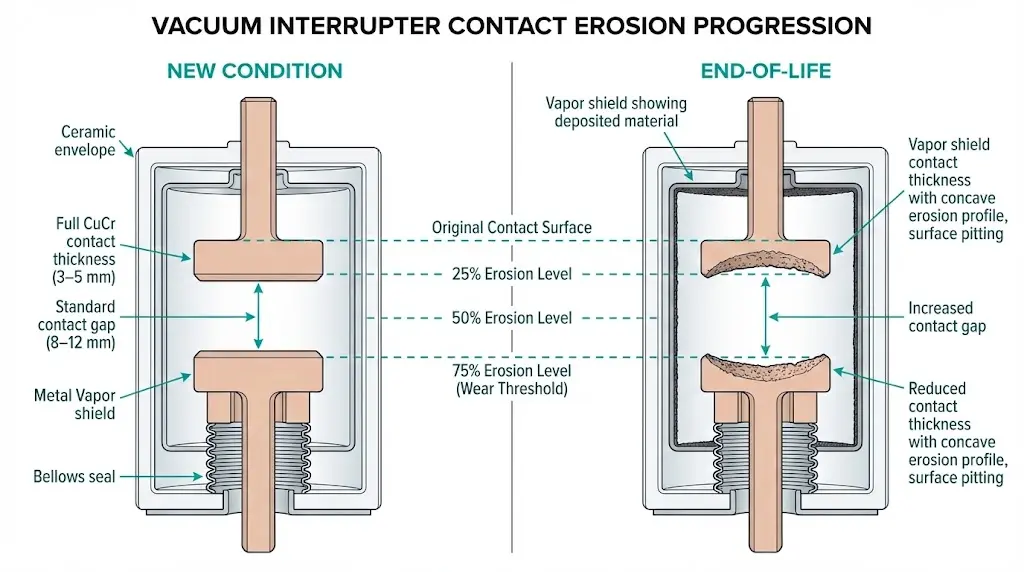
Every switching operation removes material from CuCr (copper-chromium) contact surfaces inside the vacuum interrupter. The erosion rate depends on interrupted current magnitude, arcing duration, and switching frequency—making wear assessment essential for predicting remaining service life.
When contacts separate under load, an electric arc forms across the widening gap. This arc generates localized temperatures exceeding 3,000°C at the contact surface, causing metal vaporization and material ejection. Each operation removes approximately 0.1–0.5 mg of contact material during normal load switching. Fault interruptions at 20–40 kA accelerate this loss dramatically—a single short-circuit clearing event can remove 50–100× more material than routine load switching.
The CuCr alloy composition (typically 25–50% chromium by weight) was specifically engineered to manage this thermal assault. Chromium content controls arc behavior and erosion characteristics while copper provides conductivity and heat dissipation. Despite these optimizations, cumulative erosion eventually reduces contact thickness from the original 3–5 mm specification to replacement thresholds.
Normal contact wear follows predictable patterns. Material loss occurs incrementally across thousands of operations, reducing contact thickness gradually and relatively uniformly across the contact face. This degradation can be tracked and projected using trend data.
Single-event damage presents differently. Extended arcing from slow contact separation, re-strikes during interruption, or currents exceeding rated capacity create localized craters and asymmetric erosion. These abnormal patterns may require immediate inspection regardless of cumulative operation history.
[Expert Insight: Field Observations on Wear Patterns]
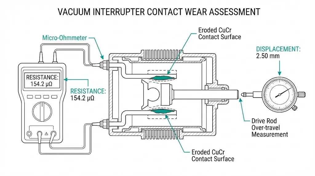
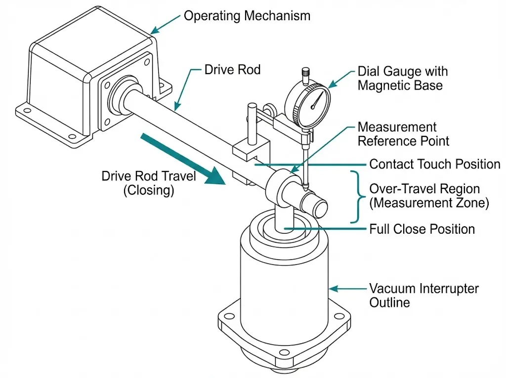
Contact gap measurement provides the most accessible field indicator of erosion severity. As contacts erode, the gap at full open position increases while over-travel (compression distance after contact touch) decreases.
Step 1: Record baseline values during commissioning. New vacuum interrupters typically maintain contact gaps of 8–12 mm for 12 kV rated equipment, with over-travel of 2–4 mm depending on manufacturer design.
Step 2: Measure current stroke length using position indicators or direct mechanical measurement at the operating mechanism. Drive rod displacement with a dial gauge provides reliable readings when external indicators are unavailable.
Step 3: Calculate contact erosion as the difference between baseline and current measurements, divided by two (erosion occurs on both contact faces).
Step 4: Compare results against manufacturer specifications. When cumulative erosion reaches 2–3 mm per contact—representing 40–60% of original thickness—most manufacturers recommend replacement regardless of other indicators.
Timing analyzers with travel transducers capture the complete stroke curve during operation. This technique reveals subtle wear signatures that manual measurements miss:
This method requires commissioning baseline data for meaningful comparison but provides earlier warning of developing problems.
Contact resistance measurement offers quantifiable data for replacement decisions without requiring VI disassembly. Fresh CuCr contacts typically exhibit resistance between 15–30 μΩ; trending this value over time reveals degradation trajectory.
Equipment: Micro-ohmmeter with 100–200 A DC injection capability and 0.1 μΩ resolution per IEEE C37.09 requirements.
Step 1: Isolate the breaker, verify de-energized status, and apply lockout-tagout procedures.
Step 2: Close breaker contacts with the mechanism charged.
Step 3: Connect micro-ohmmeter leads across terminals of the same phase—remove all parallel paths by opening disconnectors and grounding switches.
Step 4: Inject 100–200 A DC and record resistance. Take three consecutive measurements and calculate the average.
Step 5: Repeat for all three phases. Document ambient temperature (measure at 20°C ± 5°C or apply correction factor of approximately 0.4% per °C deviation).
Step 6: Compare results to commissioning baseline. Flag contacts when resistance exceeds 50 μΩ or increases more than 100% from baseline values.
Single-point measurements have limited diagnostic value. Establish baseline readings during commissioning and repeat measurements during scheduled maintenance—typically every 2,000–3,000 operations or annually for critical installations.
A consistent upward trend matters more than absolute values. Phase-to-phase deviation exceeding 30% indicates uneven wear requiring investigation. Sudden resistance increases between test intervals suggest contamination or surface damage rather than normal erosion.
[Expert Insight: Resistance Testing Best Practices]
Replacement timing requires integrating multiple indicators rather than relying on any single measurement. The following framework provides structured decision criteria based on field experience across utility and industrial installations.

Measurement intervals should match switching duty and fault exposure. Calendar-based schedules alone miss the operational factors that actually drive wear.
| Duty Category | Typical Applications | Testing Frequency |
|---|---|---|
| Normal duty | Utility substations, commercial feeders | Every 3–5 years + after any fault > 50% rated Isc |
| Heavy duty | Industrial plants, motor control centers, frequent switching | Annually or per manufacturer schedule |
| Severe duty | Mining, arc furnace supply, steel manufacturing | Every 6 months or 2,000 operations |
| Post-fault | Any breaker after interrupting > 80% rated Isc | Immediate inspection required |
Maintain trending records including: measurement date, ambient conditions, technician identification, and operation count since last test. Plot resistance and gap measurements over time—degradation trajectory reveals approaching end-of-life more reliably than absolute values at any single point.
For facilities managing multiple vacuum circuit breakers, the VCB RFQ Checklist provides a framework for standardizing replacement specifications across equipment populations.
Contact wear and vacuum loss represent independent failure modes—both require assessment. A vacuum interrupter with adequate contact thickness but degraded vacuum cannot safely interrupt current.
Flashover during dielectric testing indicates vacuum pressure has degraded below the critical threshold of approximately 10⁻² Pa, necessitating immediate replacement regardless of contact condition.
For detailed coverage of vacuum interrupter construction and failure mechanisms, see What Is a Vacuum Interrupter? which explains the relationship between vacuum integrity and interrupting performance.
When indicators reach yellow or red zone criteria, replacement VI specifications must match the original equipment precisely. Critical parameters include:
OEM replacements guarantee compatibility. Third-party alternatives require careful specification verification—dimensional mismatches affect contact force and travel, potentially compromising interrupting performance.
XBRELE manufactures vacuum interrupters and complete VCB assemblies with documented wear curves and replacement part support. For technical specifications and application guidance, visit Vacuum Circuit Breaker Manufacturer.
Understanding rated endurance specifications helps contextualize field measurements against design limits—Vacuum Circuit Breaker Ratings Explained covers electrical and mechanical endurance classes in detail.
Q: How many switching operations can vacuum interrupter contacts perform before replacement?
A: Mechanical endurance typically ranges from 10,000–30,000 operations for load switching duty, but electrical endurance depends heavily on interrupted current magnitude—fault interruptions at rated short-circuit current may limit life to 30–50 operations before contact inspection is required.
Q: Can I assess contact wear without disassembling the vacuum interrupter?
A: Yes. Over-travel measurement at the operating mechanism, contact resistance testing across terminals, and radiographic (X-ray) inspection all evaluate contact condition without breaking the VI seal.
Q: What contact resistance value indicates replacement is needed?
A: Resistance exceeding 50 μΩ or increasing more than 100% from commissioning baseline typically warrants replacement, though trending data across multiple intervals provides more reliable guidance than single measurements.
Q: Does the mechanical operation counter alone determine when to replace contacts?
A: No. Raw operation count must be weighted by interrupted current magnitude—a breaker with 500 fault interruptions may have less remaining contact life than one with 20,000 load switching operations at rated current.
Q: How does switching application affect contact wear rates?
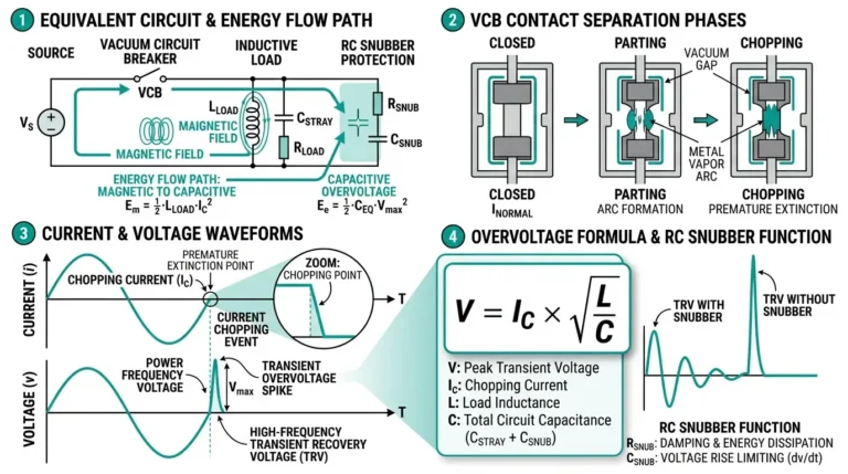
A: Motor-starting applications with 50–100 daily operations typically show 3× faster erosion than feeder protection breakers averaging only a few monthly operations. Frequent inductive load switching also accelerates wear through chopping current effects.
Q: Should vacuum integrity and contact wear be tested together?
A: Yes. These represent independent failure modes—adequate contact thickness with lost vacuum is equally dangerous as worn contacts with intact vacuum. Both assessments are necessary for complete VI health evaluation.
Q: What environmental factors accelerate contact erosion?
A: Switching frequency and fault current magnitude have the greatest impact. Altitude above 1,000 m reduces dielectric margins (requiring derating), but does not directly affect contact wear rates inside the sealed interrupter envelope.