Need Full Specifications?
Download our 2025 Product Catalog for detailed drawings and technical parameters of all switchgear components.
Get CatalogDownload our 2025 Product Catalog for detailed drawings and technical parameters of all switchgear components.
Get CatalogDownload our 2025 Product Catalog for detailed drawings and technical parameters of all switchgear components.
Get Catalog
Switchgear safety depends on knowing whether circuits are energized before maintenance work begins. Visual inspection cannot distinguish between 12 kV live and dead—workers rely on voltage presence indication systems (VPIS) to provide that confirmation. A single false indication can result in arc flash injury or fatality.
Capacitive sensors form the heart of most modern VPIS installations. Unlike potential transformers requiring insulation coordination and primary circuit modification, capacitive sensors mount externally on cables or busbars, detecting electric fields without galvanic connection. When properly selected and installed, they provide reliable voltage indication for decades. When installed incorrectly, they produce false positives, false negatives, or intermittent operation that erodes operator trust.
This guide explains how capacitive voltage sensors work, how to select appropriate models for different MV applications, proper wiring practices that prevent false indications, and troubleshooting techniques for the most common failure modes.
External Reference: Metal-enclosed switchgear framework and voltage-indication context are defined in IEC 62271-200.
Voltage Presence Indication Systems (VPIS) provide visual confirmation that circuits are energized or de-energized. They serve three critical safety functions:
Lockout/Tagout verification — Before workers approach equipment, VPIS confirms that voltage has been removed
Earthing switch permissive — Interlocks prevent earthing switch closure unless VPIS indicates voltage absent
Three-phase verification — Detects single-phasing or blown fuse conditions where one or two phases remain energized
Early VPIS implementations used voltage transformers (VTs) or potential transformers (PTs) connected directly to the primary circuit. These provide accurate voltage measurement but require careful insulation coordination, add cost, and occupy space in compact switchgear. Capacitive sensors emerged as a simpler alternative: small disc-shaped devices that mount on cable terminations, busbar chambers, or epoxy insulation surfaces, detecting voltage presence through electric field coupling.
Capacitive sensors don’t measure voltage magnitude—they detect field presence above a threshold (typically 15–25% of rated voltage). A green LED indicates voltage present; no illumination (or red LED on some models) indicates voltage absent. More sophisticated systems integrate three single-phase sensors with a central display unit showing per-phase status and alarm outputs for control circuit integration.
[SAFETY NOTE: Capacitive sensors indicate voltage presence but do NOT prove circuits are safe to touch—always verify with properly rated test equipment before working on de-energized equipment]
The vacuum circuit breaker applications discussed in this VCB working-principle guide frequently incorporate VPIS at cable terminations and busbar chambers to enhance personnel safety during maintenance and switching operations.
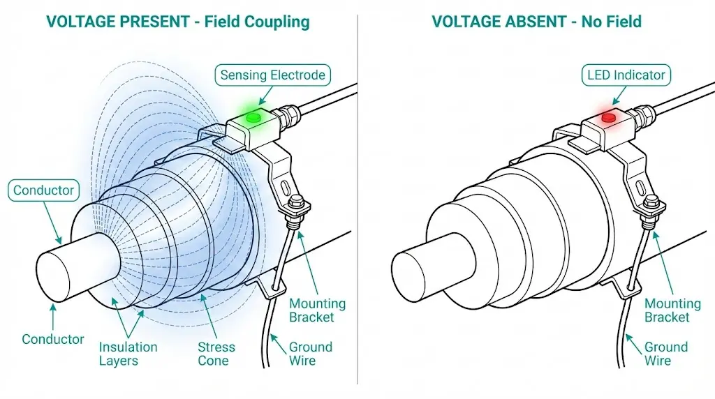
Capacitive sensors operate on the principle that energized conductors create electric fields extending into surrounding space. The sensor becomes one plate of a capacitor, with the energized conductor as the other plate and air/insulation as the dielectric.
When an MV cable or busbar is energized at 12 kV, an AC electric field radiates outward. A metallic sensing element placed near the conductor couples to this field capacitively. Even though no galvanic (direct electrical) connection exists, a tiny displacement current flows:
I = C × dV/dt
Where:
For a 50 Hz, 12 kV (phase-to-ground = ~7 kV RMS) system:
dV/dt = 2π × 50 × 7000 = 2.2 MV/s
With 1 pF coupling capacitance:
I = 1 pF × 2.2 MV/s = 2.2 μA
This microampere-level displacement current charges a small internal capacitor in the sensor’s electronics. When the accumulated charge exceeds a threshold, the sensor’s LED activates, indicating voltage presence. If the primary circuit voltage drops below ~15–25% of rated value, insufficient displacement current flows to maintain the indication.
A typical capacitive sensor contains:
Sensing electrode — Metallic disc or plate positioned close to the primary conductor
Electronics module — Amplifier, threshold detector, and LED driver powered by the sensed field itself or by harvested energy from the electric field
LED indicator — Green (voltage present) or red/none (voltage absent)
Mounting hardware — Adhesive pad, screw mount, or snap-on clip depending on application
Advanced models add:
| Sensor Type | Power Source | Typical Application |
|---|---|---|
| Self-powered (field harvesting) | Energy extracted from sensed electric field | Cable terminations, outdoor switchgear |
| Battery-powered | Internal lithium cell (5–10 year life) | Low-field applications, retrofit installations |
| Externally powered | 24 VDC or 110 VDC auxiliary supply | Systems requiring auxiliary contacts or SCADA integration |
Capacitive sensor selection depends on installation location, voltage level, environmental conditions, and system integration requirements. Incorrect selection leads to unreliable operation or complete failure.
Sensors must match the system voltage class:
| System Voltage (kV) | Sensor Pickup Threshold | Dropout Threshold | Typical Model Rating |
|---|---|---|---|
| 3.6 / 7.2 kV | 0.9–1.8 kV | 0.6–1.2 kV | 3.6 kV class |
| 12 / 13.8 kV | 1.8–3.5 kV | 1.2–2.3 kV | 12 kV class |
| 24 / 27 kV | 3.6–6.8 kV | 2.4–4.5 kV | 24 kV class |
| 36 / 40.5 kV | 5.4–10 kV | 3.6–6.8 kV | 36 kV class |
Pickup threshold — Voltage at which sensor reliably indicates “voltage present”
Dropout threshold — Voltage below which sensor indicates “voltage absent”
Hysteresis between pickup and dropout prevents LED flickering when voltage hovers near threshold. Typical hysteresis is 20–40% of pickup value.
Critical selection point: Sensors designed for 12 kV systems may fail to operate reliably on 7.2 kV systems due to insufficient field strength. Conversely, 7.2 kV sensors may indicate “voltage present” on 12 kV systems even when capacitive coupling from adjacent energized phases creates stray fields—leading to false positives.
Cable terminations (most common):
Busbar chambers:
Epoxy insulated bushings/parts:

[Application Note: Sensor Placement for Maximum Reliability]
- Mount sensors within the equipotential grounding zone—never on isolated metal that could float to dangerous voltage
- Position sensors where they couple to the intended phase conductor only—avoid locations sensing multiple phases simultaneously
- Verify that sensor LED is visible from normal operator position without requiring panel opening
- On cable terminations, mount sensors on the straight section below the stress cone, not on the flared portion
Capacitive sensors must withstand the installation environment:
| Environment | Required Ratings | Typical Challenges |
|---|---|---|
| Indoor switchgear (clean) | IP40, -5°C to +40°C | Minimal environmental stress |
| Indoor industrial (dusty) | IP54, -10°C to +50°C | Dust accumulation on sensor face can reduce coupling |
| Outdoor distribution (temperate) | IP65, -40°C to +70°C, UV resistance | Condensation, temperature cycling, UV degradation |
| Outdoor coastal (corrosive) | IP66/IP67, -40°C to +85°C, salt fog tested | Corrosion of terminals, moisture ingress |
| Mining/heavy industrial | IP67, vibration rated, -25°C to +60°C | Mechanical shock, dust, vibration affecting LED visibility |
Temperature extremes affect both electronics reliability and battery life (for battery-powered models). Sensors rated only to +40°C may fail prematurely in outdoor switchgear experiencing direct solar heating—internal temperatures can exceed +70°C.
Basic sensors provide local visual indication only. Applications requiring remote monitoring or electrical interlocks need sensors with auxiliary contacts:
SPDT relay output:
Common uses:
Sensors with contacts require external power (cannot be self-powered from electric field alone). Connection requires additional wiring—typically 3–4 wires for power supply plus 2–3 wires per contact.
Capacitive sensors are simple devices, yet improper wiring causes the majority of field failures and false indications. Most issues trace to grounding errors, electromagnetic interference, or contact wiring mistakes.
Capacitive sensors must be grounded to the switchgear ground bus to establish a reference potential:
Correct grounding practice:
Cable shielding (for sensors with auxiliary contacts):
| Wiring Error | Consequence | Correct Practice |
|---|---|---|
| Sensor not grounded | Erratic operation, false positives from stray fields | Dedicated ground wire to switchgear ground bus |
| Shield grounded at both ends | Ground loop current causes false indications | Ground shield at sensor end only |
| Sensor cable routed with power cables | EMI-induced false indications | Route sensor cables in separate conduit/tray |
| Sensor mounted on painted surface | Intermittent operation due to poor ground contact | Remove paint at mounting point or use grounding strap |
Sensors with relay outputs require careful attention to contact wiring polarity and configuration:
For earthing switch interlock:
For alarm indication:
Critical: Verify contact type (NO vs NC) matches circuit requirement. Some manufacturers label contacts using “working” vs “resting” terminology instead of “a”/“b”—consult manufacturer documentation to avoid wiring errors.

Self-powered sensors harvest energy from the sensed electric field—no external wiring required. Battery-powered and externally-powered sensors require proper supply connection:
Battery-powered:
Externally-powered:
Power supply wiring:
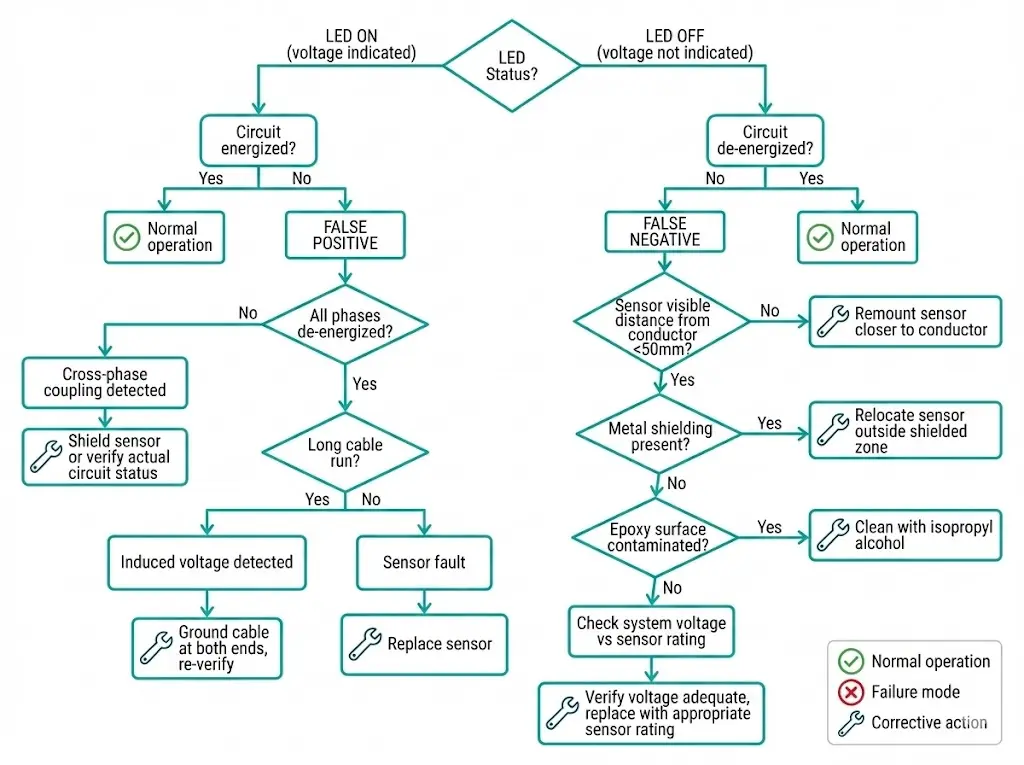
False positives (indicating voltage present when circuit is dead) and false negatives (failing to indicate voltage when circuit is energized) undermine operator confidence in VPIS. Understanding root causes enables effective troubleshooting.
Cause 1: Capacitive coupling from adjacent energized phase
Solution: Shield sensor from adjacent phase fields using grounded metal barriers, or relocate sensor to position with less cross-coupling. Some installations require phase-selective sensors with directional sensing elements.
Cause 2: Induced voltage on long de-energized cable
Solution: Ground the de-energized cable through temporary earthing before relying on VPIS indication. Alternatively, use sensors with higher pickup threshold or dual-confirmation (voltage measurement + field sensing).
Cause 3: Sensor electronics failure
Solution: Replace faulty sensor. Check for environmental damage (moisture ingress, overheating) that may have caused failure.
Cause 1: Sensor positioned too far from conductor
Solution: Remount sensor in proper location. For retrofit installations where mounting position is constrained, consider higher-sensitivity sensor model.
Cause 2: Shielding by grounded metal
Solution: Relocate sensor to position outside shielded zone, or install busbar-mounted sensor that bypasses chamber shielding.
Cause 3: Contamination on epoxy surface
Solution: Regular cleaning of sensor mounting surfaces. For outdoor installations, verify IP rating adequate to prevent moisture ingress.
Cause 4: Low system voltage
Solution: Replace sensor with lower-voltage-rated model appropriate for actual operating voltage.
Cause 5: Battery depletion (battery-powered sensors)
Solution: Replace battery or replace entire sensor if battery non-serviceable.
| Symptom | Most Likely Cause | Quick Verification Test |
|---|---|---|
| All three phases indicate voltage when one de-energized | Cross-phase coupling | De-energize all phases—indications should disappear |
| Intermittent indication (flickering LED) | Marginal field strength or poor ground connection | Check sensor mounting tightness and ground wire continuity |
| One phase never indicates even when energized | Sensor failure or positioning error | Swap sensors between phases to isolate faulty unit |
| Sudden failure of all sensors simultaneously | Power supply failure (externally-powered sensors) | Verify control supply voltage at sensor terminals |
Proper installation extends sensor life and maintains reliable operation for years:

Capacitive sensors are largely maintenance-free but require periodic verification:
Annual inspection:
5-year detailed test:
10-year replacement consideration:
After fault events:
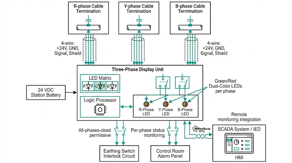
Basic installations use independent sensors per phase. Advanced systems integrate three sensors with centralized logic and remote monitoring.
Centralized display units consolidate three single-phase sensors:
Features:
Wiring:
Advantages over independent sensors:
Modern switchgear integrates VPIS with intelligent electronic devices (IEDs) and SCADA:
Communication protocols:
Data points transmitted:
Applications:
Sensor quality varies significantly among manufacturers. When evaluating suppliers:
Verify type test certification: Sensors should have independent test reports confirming voltage threshold, temperature performance, and EMC immunity per IEC 61243-5 (live working—voltage detecting devices).
Check application experience: Has the supplier provided sensors for similar applications (same voltage class, environment, mounting type)?
Evaluate technical support: Can the supplier assist with sensor placement optimization and troubleshooting false indication issues?
Assess spare parts availability: Sensors may remain in service 20+ years—ensure replacement units and batteries remain available.
Review warranty terms: Minimum 2-year warranty standard; some manufacturers offer 5 years for premium models.
XBRELE provides capacitive voltage sensors engineered for reliable operation in MV switchgear applications from 3.6 kV through 40.5 kV. Our sensors feature dual-LED indication (green + red), self-test functionality, and auxiliary contacts for interlock integration. Complete installation documentation, commissioning support, and spare parts availability ensure long-term system reliability. Explore our full range of switchgear components and accessories in this vacuum circuit breaker manufacturer guide.
Q1: Do capacitive sensors require physical connection to the high-voltage conductor?
A: No. Capacitive sensors operate through electric field coupling and require no galvanic (direct electrical) connection to the MV conductor. They mount externally on cable insulation, busbar chambers, or epoxy surfaces, sensing the electric field radiated by energized conductors.
Q2: Can capacitive sensors measure the actual voltage value?
A: No. Capacitive sensors detect voltage presence/absence only, not magnitude. They indicate whether voltage exceeds a threshold (typically 15–25% of rated voltage) but do not provide numeric voltage readings. For voltage measurement, use voltage transformers or electronic voltage transducers.
Q3: What causes capacitive sensors to indicate voltage present when the circuit is actually de-energized?
A: Common causes include capacitive coupling from adjacent energized phases, induced voltage on long de-energized cables running parallel to energized cables, and sensor electronics failure. Troubleshooting involves verifying all phases are de-energized, checking for induced voltage with a high-impedance voltmeter, and testing sensor function.
Q4: How long do battery-powered capacitive sensors last before battery replacement?
A: Battery life typically ranges from 5 to 10 years depending on sensor model, ambient temperature, and LED activation frequency. Most battery-powered sensors provide low-battery warning (LED flash pattern) 6–12 months before complete battery depletion.
Q5: Can I install a 12 kV-rated sensor on a 24 kV system?
A: No. Sensors must be rated for the system voltage class. Installing a lower-voltage-rated sensor on a higher-voltage system risks sensor damage and unreliable operation. Electric field strength at higher voltages may saturate sensor electronics or exceed component ratings.
Q6: Why does my sensor work reliably in winter but fail to indicate in summer?
A: Temperature affects sensor electronics and battery performance. If the sensor is rated only to +40°C but experiences +70°C in summer (due to solar heating or proximity to transformers), electronics may malfunction or battery voltage may drop below operating threshold. Verify sensor temperature rating exceeds maximum expected ambient temperature by at least 10°C.
Q7: How close must a capacitive sensor be positioned to the conductor for reliable operation?
A: Effective sensing distance depends on voltage level and sensor design. Typical ranges: 3.6–12 kV systems require sensor within 50 mm of conductor; 24–36 kV systems may operate reliably up to 100 mm distance. Consult manufacturer specifications for specific models. Field strength decreases rapidly with distance—doubling distance reduces signal strength by 75% or more.