Request a Quote for High-Voltage Components&Equipment

Tell us your requirements — rated voltage, model, quantity, and destination — and our XBR Electric team will prepare a detailed quotation within 24 hours.
Contact Form Demo
Wall bushing vs through-wall insulator diagram for MV switchgear partitions

Wall Bushing vs Through-Wall Insulator (MV)

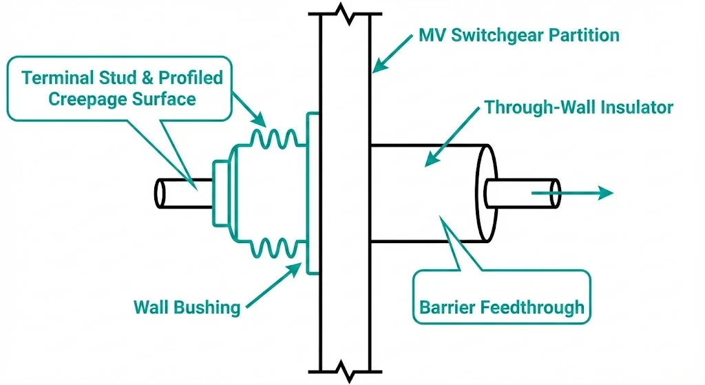
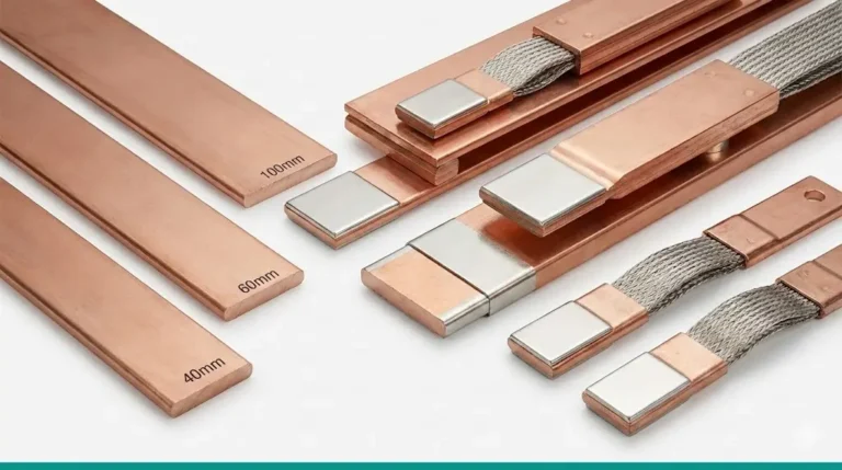
A wall bushing is an insulated primary-conductor feedthrough that carries a conductor through a grounded barrier (panel, partition, or tank wall) while controlling electric stress at the wall edge. It is typically a small system: conductor (rod/tube/stud), insulation body (epoxy/resin/ceramic/polymer), and a defined terminal interface (studs, pads, lugs, busbar faces). In MV switchgear you commonly see it applied around system classes such as 12 kV12\ \text{kV}12 kV and 24 kV24\ \text{kV}24 kV, where wall cutout geometry, creepage shaping, and terminal hardware edges can matter as much as bulk insulation thickness. For bushing products above 1 kV1\ \text{kV}1 kV, IEC 60137 is commonly referenced for bushing ratings and test practices.

A through-wall insulator (through-partition insulator) is primarily an insulating barrier component that maintains dielectric separation across a wall. It can include a passage for a conductor or cable, but it does not automatically include a bushing-style terminal system or a current-rated interface; its design emphasis is insulation continuity and sealing at the penetration.

What a wall bushing is not: a generic grommet or sleeve. If there is no controlled terminal/electrode geometry and no attention to the grounded wall edge, it is not doing bushing work. What a through-wall insulator is not: a guaranteed drop-in substitute when you need repeatable torque joints and a defined current path.

Cross-section comparing a wall bushing and a through-wall insulator in a grounded partition
Cross-sectional schematic contrasting terminal-defined wall bushings with barrier-focused through-wall insulators at a grounded partition interface.

Internal structure & dielectric path: why “they look similar” but behave differently

Both parts can look like “an epoxy cylinder in a steel wall.” The difference is what the design controls versus what it leaves to assembly.

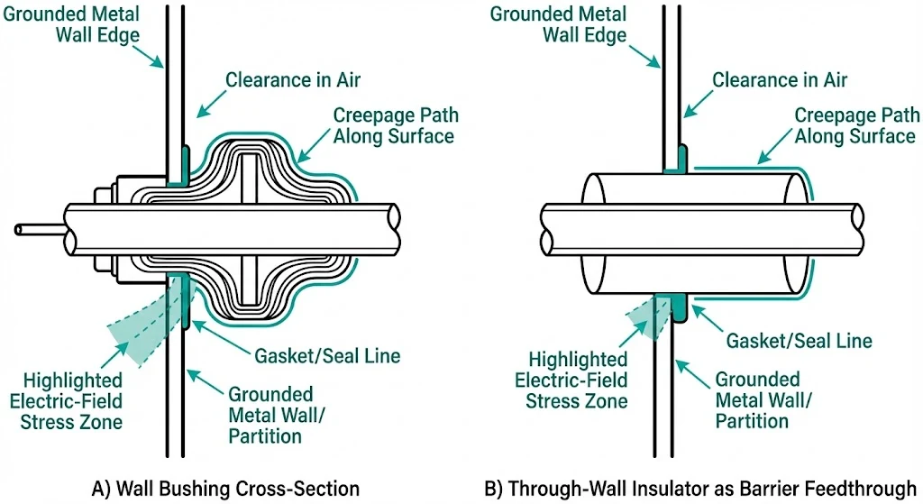
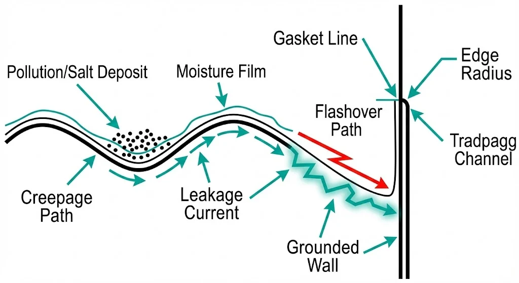
A wall bushing is built around a defined electrode system: the conductor and its terminal hardware set equipotential surfaces that shape the local field. The dielectric path is engineered through interfaces—metal → solid insulation → surface/air → grounded wall—so geometry decides where stress concentrates. As an illustrative example, a sharp burr with an effective radius near 0.5 mm0.5\ \text{mm}0.5 mm can significantly intensify local stress compared with a more radiused edge around 3 mm3\ \text{mm}3 mm, depending on spacing and hardware shape. This is why many bushing designs “spend” geometry budget near the wall transition.

A through-wall insulator behaves more like a barrier. It prioritizes insulation continuity through the wall and sealing integrity. If terminal electrodes are not controlled by the component, the stress picture can be dominated by “field hardware”: lug stack shape, washer selection, busbar pad edges, and how close metal sits to the grounded wall.

Service-relevant differences to look for on the drawing:

  • Terminal definition (controlled vs integration-defined)
  • Stress control features near the grounded wall edge
  • Creepage shaping (profiled vs flat wet paths)
  • Seal boundary placement (does moisture sit where stress is highest?)
  • Insert / interface quality (voids and sharp edges can become PD starters)

For PD measurement language, IEC 60270 is the commonly used reference for the measurement method (test circuit concepts and calibration).

[Expert Insight]

  • If the lug stack is “installer-defined,” require a drawing of the exact hardware stack-up and a torque window; otherwise the electric stress profile varies by installation.
  • Subtle resin separation around an insert can pass a quick visual check yet become a PD site once humidity and thermal cycling accumulate.
  • A withstand report is necessary, but it doesn’t remove risk created by a sharp wall edge plus a short wet creepage path.

Comparison table: selection-critical parameters that actually decide the “vs”

Use this table to lock the decision to checkable parameters (drawing + datasheet), not naming.

Decision parameterWall bushing (typical)Through-wall insulator (typical)Why it matters
System classExplicit (e.g., 12 kV12\ \text{kV}12 kV, 24 kV24\ \text{kV}24 kV)Explicit, sometimes barrier-focusedAligns with insulation coordination
Impulse / BILOften explicitSometimes implicitSurges expose weak geometries
Power-frequency withstandExplicitExplicitBaseline dielectric margin
Creepage distanceProfiled surfaces commonVaries widelyWet contamination pushes creepage to the limit
Air clearance near wallControlled by designOften influenced by external hardwareHardware can erase margin in mm
Terminal interfaceDefined stud/pad/lugMay be minimalTorque and contact repeatability
Current ratingTypically explicit (A)Not always applicable/explicitIf it carries primary current, require an A rating
Mounting envelopeTight definition (cutout/bolt circle)Variable across vendorsRetrofits fail on mm differences
Sealing strategyOften integrated at wall edgeOften sealing-firstMoisture at wall edge is a common trigger

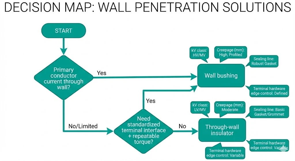
A practical discriminator: if you must bolt a busbar/cable lug to a conductor through the wall with a specified torque (e.g., 35 N\cdotpm35\ \text{N·m}35 N\cdotpm), you are usually dealing with a wall bushing requirement. If the penetration’s main job is barrier/sealing and the terminals are not the controlling interface, a through-wall insulator can be appropriate—provided withstand and geometry are explicitly stated.

Decision flowchart for choosing wall bushing vs through-wall insulator
Selection decision map linking conductor/terminal requirements to the preferred wall penetration component type.

Standards mapping (don’t guess): IEC 60270 (PD measurement method) and IEC 60137 (bushing products above 1 kV1\ \text{kV}1 kV) are commonly used references. If you need the governing standard for dielectric test requirements of the metal-enclosed switchgear assembly (as opposed to the standalone part), confirm it before citing.


Application mapping: where each one is commonly used in MV gear

Map the location to the interface you actually need:

  1. Cable compartment → busbar partition (primary current crossing)Wall bushing (defined current path + terminals).
  2. Busbar chamber partition between sectionsWall bushing (repeatable geometry).
  3. Instrument wiring penetrations (VT/CT secondary)Through-wall insulator (barrier + sealing).
  4. Compact RMU barriersDepends: bolted primary conductor → bushing; sealed barrier penetration → through-wall.
  5. Condensation-prone enclosures where sealing dominatesOften through-wall, unless primary current needs a bushing interface.
  6. Retrofit with fixed lug geometryWall bushing (terminal match is usually the constraint).
  7. Retrofit driven by wall thickness / cutout changesThrough-wall insulator (mechanical envelope dominates).
  8. Thermal gradient near primary jointsLean wall bushing if primary current is involved; torque stability matters when compartments swing, for example, 60 C60\ ^\circ\text{C}60 ∘C to 90 C90\ ^\circ\text{C}90 ∘C.

Field conditions that flip the decision (pollution, condensation, altitude, salt fog)

Field reality often penalizes the surface and the wall edge first. Use this checklist to decide when “barrier-only” becomes risky.

  1. Pollution + wetting: surface leakage dominates.
    Mitigation: longer creepage geometry (mm), avoid straight wet paths.
  2. Condensation cycles: moisture sits at the gasket line, then leaves conductive residue.
    Mitigation: stable sealing and geometry that does not trap water.
  3. Salt fog/coastal: conductivity rises; tracking initiates at stress points.
    Mitigation: protect terminals and avoid sharp exposed metal.
  4. Altitude: reduced air density reduces external insulation margin.
    Mitigation: treat air clearances (mm) as a hard requirement in the installed configuration.
  5. Thermal cycling at terminals: microgaps and loosening accelerate aging.
    Mitigation: controlled terminal geometry and torque discipline; consider re-checking after 505050–100100100 cycles if your maintenance plan allows.
  6. Poor cutout workmanship: burrs and sharp edges concentrate stress.
    Mitigation: deburr and radius; even a 0.5 mm0.5\ \text{mm}0.5 mm burr can consume margin in compact layouts.
Contamination and condensation creating surface leakage and tracking at a wall penetration
Field mechanism schematic illustrating how contamination and moisture films can drive surface leakage and tracking near a grounded wall interface.

[Expert Insight]

  • When a flashover looks “random,” inspect the wall edge finish and hardware geometry first; many failures track along a wet surface path, not through the resin body.
  • In wet/dirty gear, cleanliness at the gasket and terminals is part of dielectric design, not housekeeping.
  • In retrofits, mechanical support that removes lever load from the terminal can slow crack growth and reduce interface fretting.

Testing & acceptance cues: what to ask suppliers and what to inspect on arrival

RFQ / submittals (ask before purchase)

  • Withstand values: power-frequency (kV) and impulse/BIL (kV) for the exact configuration (including terminals).
  • Voltage class + drawing revision: tie part number to drawing and 12 kV12\ \text{kV}12 kV / 24 kV24\ \text{kV}24 kV class as applicable.
  • Creepage + clearance: creepage (mm) and minimum air clearance (mm) around wall and terminals.
  • Terminal details (bushing): stud/pad dimensions and torque guidance (e.g., 353535–70 N\cdotpm70\ \text{N·m}70 N\cdotpm, interface-size dependent).
  • Sealing method: gasket material and compression range.
  • Material window: temperature range (often 25 C-25\ ^\circ\text{C}−25 ∘C to +85 C+85\ ^\circ\text{C}+85 ∘C for indoor equipment—confirm for your application).
  • PD information (if provided): reporting method language consistent with IEC 60270.
  • Tolerances: cutout/bolt circle/terminal concentricity in mm.

Incoming inspection (receive + pre-install)

  • Inspect microcracks and insert bonding (bright light; focus on insert transitions).
  • Verify terminal geometry and critical dimensions (mm) to the drawing.
  • Check gasket seat flatness; confirm the panel cutout is deburred and radiused (targets like 222–3 mm3\ \text{mm}3 mm radius are common where practical, but follow your drawing/spec).
  • Dry-fit for alignment before final assembly.

Practical selection workflow + sourcing note

A repeatable workflow beats appearance-based substitution.

  1. Confirm whether a primary conductor crosses the wall. If yes, the requirement usually points toward a wall bushing; if no, a through-wall insulator may be sufficient.
  2. Set insulation targets in numbers: system class (e.g., 12 kV12\ \text{kV}12 kV, 24 kV24\ \text{kV}24 kV), plus power-frequency (kV) and impulse/BIL (kV) for the installed configuration.
  3. Lock the envelope: cutout, bolt circle, wall thickness, terminal orientation. A mismatch of even 2 mm2\ \text{mm}2 mm can break interchangeability.
  4. Apply environment penalties (pollution/condensation/salt/altitude) to creepage (mm), sealing, and hardware geometry.
  5. Decide maintainability: if replacement time is constrained (e.g., 606060–120 min120\ \text{min}120 min windows), standardized terminals reduce variability.
  6. Attach the incoming inspection checklist to the PO.

If you want XBRELE to recommend the best-fit configuration, share your voltage class (kV), wall thickness (mm), terminal style, and environment notes. We’ll map you to the right geometry and acceptance cues: wall bushing options.


FAQ

Q1: What’s a practical sign that a through-wall insulator might be the wrong choice?
If the design depends on controlled terminal contact pressure and a defined current path, a bushing-style interface is typically lower risk.

Q2: Why can two parts with the same cutout still behave differently?
Surface profile, sealing boundary placement, and the installed hardware edges can shift local stress and wet-surface leakage behavior.

Q3: If PD data isn’t available, what can I tighten instead?
Dimensional tolerances, defined terminal geometry, workmanship controls around inserts, and a disciplined receiving inspection help reduce variability.

Q4: Which field condition most often forces a re-think?
Persistent condensation combined with contamination tends to expose short wet creepage paths and weak sealing boundaries.

Q5: Is wall cutout finish really selection-critical?
Often, yes—sharp edges and burrs concentrate electric stress; controlled deburring and radius are a low-cost way to preserve margin.

Q6: What’s a conservative retrofit approach when drawings are incomplete?
Measure the existing interface in mm, document the hardware stack-up, and avoid assuming interchangeability based on external appearance.

Hannah Zhu marketing director of XBRELE
Hannah

Hannah is the Administrator and Technical Content Coordinator at XBRELE. She oversees website structure, product documentation, and blog content across MV/HV switchgear, vacuum breakers, contactors, interrupters, and transformers. Her focus is delivering clear, reliable, and engineer-friendly information to support global customers in making confident technical and procurement decisions.

Articles: 61