Need Full Specifications?
Download our 2025 Product Catalog for detailed drawings and technical parameters of all switchgear components.
Get CatalogDownload our 2025 Product Catalog for detailed drawings and technical parameters of all switchgear components.
Get CatalogDownload our 2025 Product Catalog for detailed drawings and technical parameters of all switchgear components.
Get Catalog
The “Heart” of VCBs: The Vacuum Interrupter (VI) is the globally accepted standard for medium-voltage switching, utilizing Metal Vapor Arc Extinction in a high-vacuum chamber (< 10⁻⁵ Pa) to interrupt massive fault currents.
Selection Verdict: For OEMs requiring IEC-compliant endurance (Class E2/M2), XBRELE vacuum interrupters provide a superior, eco-friendly alternative to SF6, delivering factory-direct precision for 12kV–40.5kV grids.
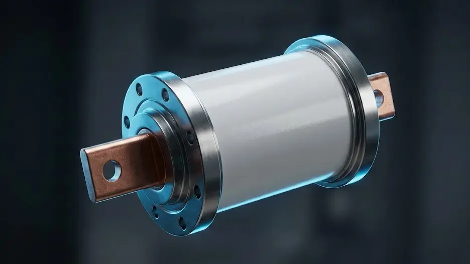
In the critical infrastructure of medium voltage (MV) and high voltage (HV) power distribution, the reliability of the entire protection system often comes down to a single component: the switch. While the external operating mechanism provides the necessary kinetic energy and the relay logic acts as the brain, the actual physical task of isolating massive fault currents happens within a hermetically sealed ceramic chamber—the Vacuum Interrupter (VI).
Often referred to as the “heart” or “bottle” of a vacuum circuit breaker, the VI is an engineering marvel. It is responsible for making and breaking currents ranging from nominal load currents of 630A to short-circuit fault currents exceeding 63 kA.
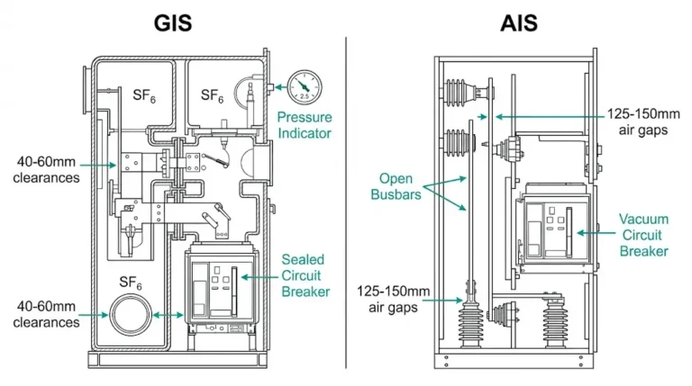
Unlike legacy technologies such as oil or SF6 (sulfur hexafluoride), vacuum technology has become the dominant standard for 12kV–40.5kV applications.
For OEM buyers and switchgear designers, a superficial understanding of VIs is no longer sufficient. The distinction between a premium VI and a reliable failure lies in microscopic details: the gas content of the copper, the magnetic field geometry, and the brazing integrity. This article provides an authority-level dissection to help you evaluate quality.
Technically defined, a Vacuum Interrupter is a specialized switchgear component that utilizes a high-vacuum environment (typically 10⁻⁵ Pa or better) as the dielectric medium for arc quenching and insulation.
Because a “perfect” vacuum contains no ionizable gas molecules, it possesses a dielectric strength significantly higher than air or SF6 at comparable gaps. This allows the contact gap to be remarkably small—often just 6mm to 20mm—resulting in a compact, low-energy operating mechanism.
For a quick reference, here are the standard parameters engineers generally encounter:
| Parameter | Typical Value / Characteristic |
|---|---|
| Rated Voltage | 1.14 kV to 40.5 kV (up to 72.5 kV for single break) |
| Rated Current | 630 A to 5000 A |
| Short Circuit Breaking Current | 16 kA to 63 kA (up to 80 kA typical) |
| Contact Gap | 6mm (12kV) to 20mm (40.5kV) |
| Mechanical Life | 10,000 to 30,000 operations (Class M2) |
| Electrical Life (Short Circuit) | 30 to 100 operations (Class E2) |
| Internal Pressure | < 1.33 × 10⁻³ Pa (at end of shelf life) |
To understand why vacuum is so effective, engineers refer to Paschen’s Law. The law describes the breakdown voltage as a function of pressure (p) and gap distance (d).
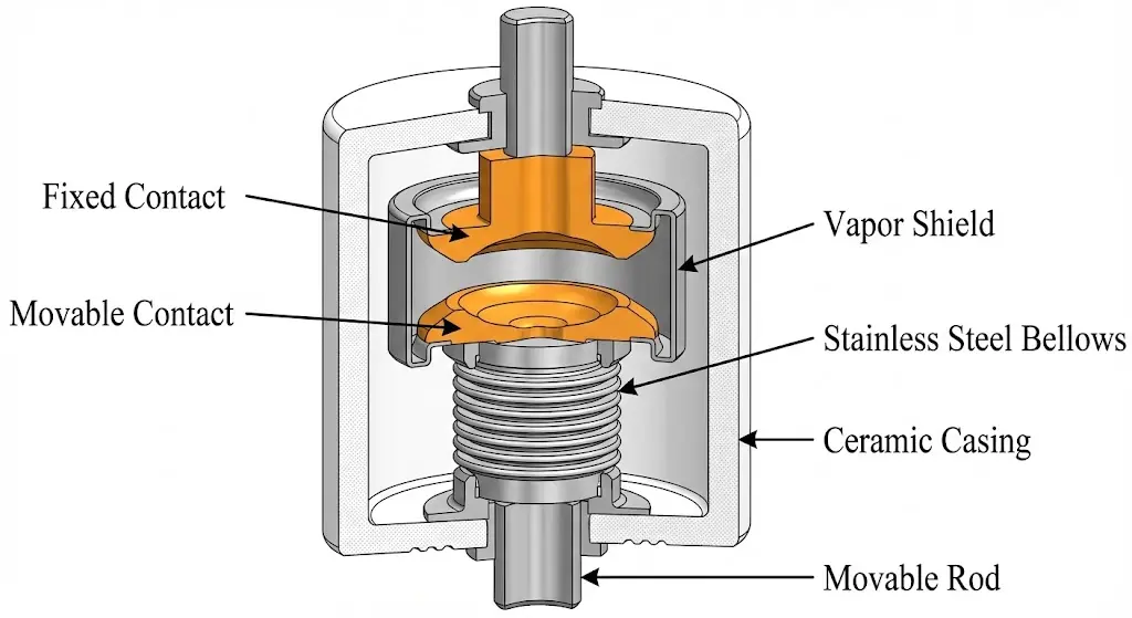
A vacuum interrupter is a complex assembly of high-purity materials joined by advanced vacuum furnace brazing.
The contacts are the most critical element. They must conduct heat efficiently, withstand arc erosion, and prevent welding.
The bellows is the only moving part of the vacuum envelope. It allows the moving contact to travel without breaking the hermetic seal.
Surrounds the arc gap to intercept explosive metal vapor generated during interruption.
For a detailed breakdown, refer to our guide on vacuum circuit breaker parts.
The structural integrity of the VI depends on how these components are joined. Premium manufacturers like XBRELE utilize a “One-Shot Brazing” technique. Instead of multiple heating cycles which can weaken materials and introduce stress, all components are assembled and brazed in a high-vacuum furnace in a single cycle. This ensures perfect axial alignment and minimizes the heat-affected zones in the metal structure.
In a vacuum, there is no gas to ionize. The arc is a Metal Vapor Arc, sustained by ions (vaporized Cu/Cr) and electrons emitted from cathode spots (microscopic pools of molten metal on the negative contact).
At current zero (AC cycle), the energy input stops. The cathode spots extinguish. The metal vapor expands explosively into the vacuum (diffusing at ~1000 m/s) and condenses on the shields and contacts. The dielectric strength recovers in microseconds—faster than the rising Transient Recovery Voltage (TRV), preventing re-ignition.

At high fault currents (>10kA), the arc’s own magnetic field causes it to constrict into a tight, incredibly hot column that can destroy contacts. Engineers use magnetic fields to control this.
Engineering Selection Tip: For generator circuit breakers or heavy-duty cycles where contact life is paramount, AMF is preferred due to lower thermal stress. For standard distribution networks, RMF provides a robust and economical solution.
A Vacuum Interrupter does not work in isolation; it requires a precise mechanical operating mechanism. For OEM engineers integrating VIs into their breakers, three parameters are critical:
Because vacuum contacts are butt contacts, they rely on external spring pressure to maintain low resistance and prevent welding during short-circuit “make” operations.
The mechanism must continue to move after the contacts touch. This compresses the contact pressure spring.
When contacts slam shut, they naturally bounce.
Historically, VIs were mounted inside insulating cylinders (assembled poles). The modern trend is Solid Insulation Embedded Poles.
Each short circuit vaporizes ~1-3mm of contact material over its life. XBRELE VIs meet Class E2 (IEC 62271-100), capable of extended short-circuit operations without maintenance.
How do you know a VI has failed?
A high-quality vacuum interrupter typically has a service life of 20 to 30 years. Mechanically, standard VIs are rated for Class M2 (10,000 to 30,000 operations). Electrically, they can withstand Class E2 (up to 100 full short-circuit interruptions) depending on the contact material and design.
The only reliable method to test vacuum integrity in the field is a Vacuum Bottle Tester (Vidar Test). This involves applying a high DC or AC voltage (typically 75% of the rated power frequency withstand voltage) across the open contacts. If the vacuum is intact, leakage current is negligible; if the vacuum is compromised, a flashover will occur immediately.
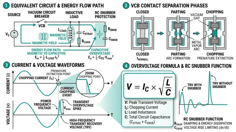
The main disadvantage is the risk of current chopping when switching small inductive currents, which can cause transient overvoltages (V = L · di/dt). Additionally, vacuum interrupters become less economical at extremely high voltages (above 72.5 kV or 145 kV) where multiple breaks in series are required compared to SF6 alternatives.
The industry standard material is Copper-Chromium (CuCr), typically in a 50/50 or 75/25 ratio. This alloy is chosen because copper provides excellent electrical conductivity, while chromium offers a high melting point and strong “gettering” ability to absorb residual gases and maintain the vacuum.
Vacuum circuit breakers are preferred because they are environmentally friendly (zero greenhouse gas emissions) and require virtually no maintenance. While SF6 is a potent greenhouse gas facing strict global phase-out regulations, vacuum technology is sustainable, offers higher mechanical endurance, and eliminates the risk of gas leakage.
During manufacturing, the internal pressure is reduced to less than 10⁻⁵ Pa. For a vacuum interrupter to maintain its dielectric strength and arc-quenching capability throughout its lifespan, the internal pressure must remain below the critical threshold of 10⁻² Pa.
No, a vacuum interrupter cannot be repaired. It is a hermetically sealed unit with brazed ceramic-to-metal joints. Once the vacuum seal is broken or the contacts are eroded beyond their limit, the entire interrupter (or embedded pole) must be replaced.
The vacuum interrupter is the defining component of modern switchgear. However, internal quality varies. A premium VI with superior brazing, high-purity CuCr contacts, and precise AMF design ensures decades of safety.
Partner with Engineering Excellence At XBRELE, we engineer safety. Our VIs exceed IEC 62271-100 and ANSI/IEEE C37.60 standards. Whether for integrated VCBs or OEM supply, we power your grid.
A deep dive into the “heart” of MV switchgear. This guide covers arc extinction physics in a high vacuum, ceramic-to-metal brazing technology, and CuCr contact material science.
Download VI Engineering Guide