Need Full Specifications?
Download our 2025 Product Catalog for detailed drawings and technical parameters of all switchgear components.
Get Catalog
Download our 2025 Product Catalog for detailed drawings and technical parameters of all switchgear components.
Get Catalog Download our 2025 Product Catalog for detailed drawings and technical parameters of all switchgear components.
Get Catalog
Technical Level: Intermediate to Advanced
Applicable Standards: IEC 60076, IEEE C57.12.00In the hierarchy of power system assets, the 3-phase transformer is the most critical node. Beyond simple voltage transformation, it acts as a harmonic filter, a tool for grounding strategy, and a robust barrier against fault propagation.
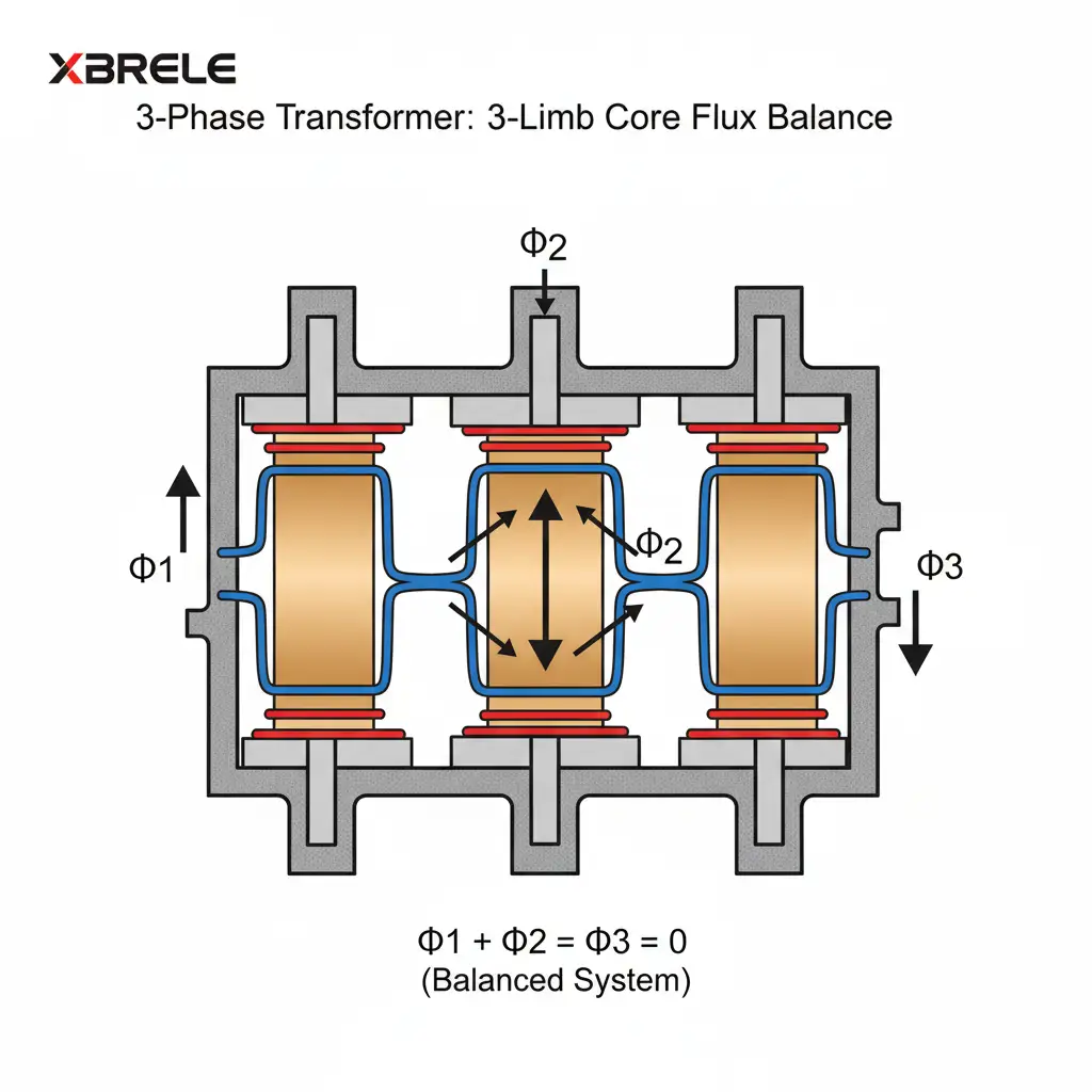
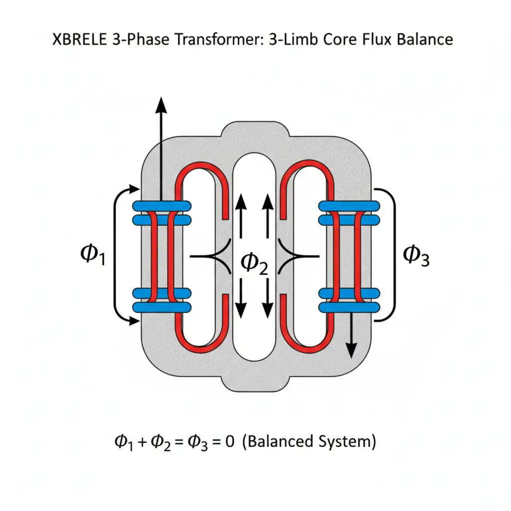
A 3-phase transformer utilizes a coupled magnetic circuit that exploits the unique properties of balanced 3-phase systems.
In a balanced 3-phase system, the sum of the instantaneous fluxes at any point in time is zero:
Φ1 + Φ2 + Φ3 = 0
This physical property allows for a 3-limb core design, typically utilizing Cold Rolled Grain Oriented (CRGO) silicon steel. By using the central limbs as return paths for each other, this architecture significantly reduces the material requirements, thereby lowering No-Load Losses (Iron Losses) and optimizing the physical footprint of the unit.
Designers must carefully balance Magnetic Flux Density (B), typically targeted between 1.5 T and 1.7 T. Over-excitation, often caused by over-voltage or low frequency (an abnormal V/f ratio), leads to significant technical risks:
For B2B procurement, the transformer’s total ownership cost (TOC) is often more critical than the initial purchase price.
Total Losses = No-Load Losses + Load Losses
The choice of connection determines the system’s zero-sequence impedance and its response to asymmetrical faults.
| Connection Type | IEC Symbol | IEEE Term | Advantage | Limitation |
|---|---|---|---|---|
| Star | Y / y | Wye | Neutral point available; graded insulation reduces costs. | Vulnerable to unbalanced 3<sup>rd</sup> harmonic flux. |
| Delta | D / d | Delta | Traps 3<sup>rd</sup> harmonics; high fault current capacity. | No neutral for grounding; full line insulation required. |
| Zig-Zag | Zn / zn | Interconnected Star | Ideal for balancing extreme load asymmetry. | Increased copper usage (~15% more than Star). |
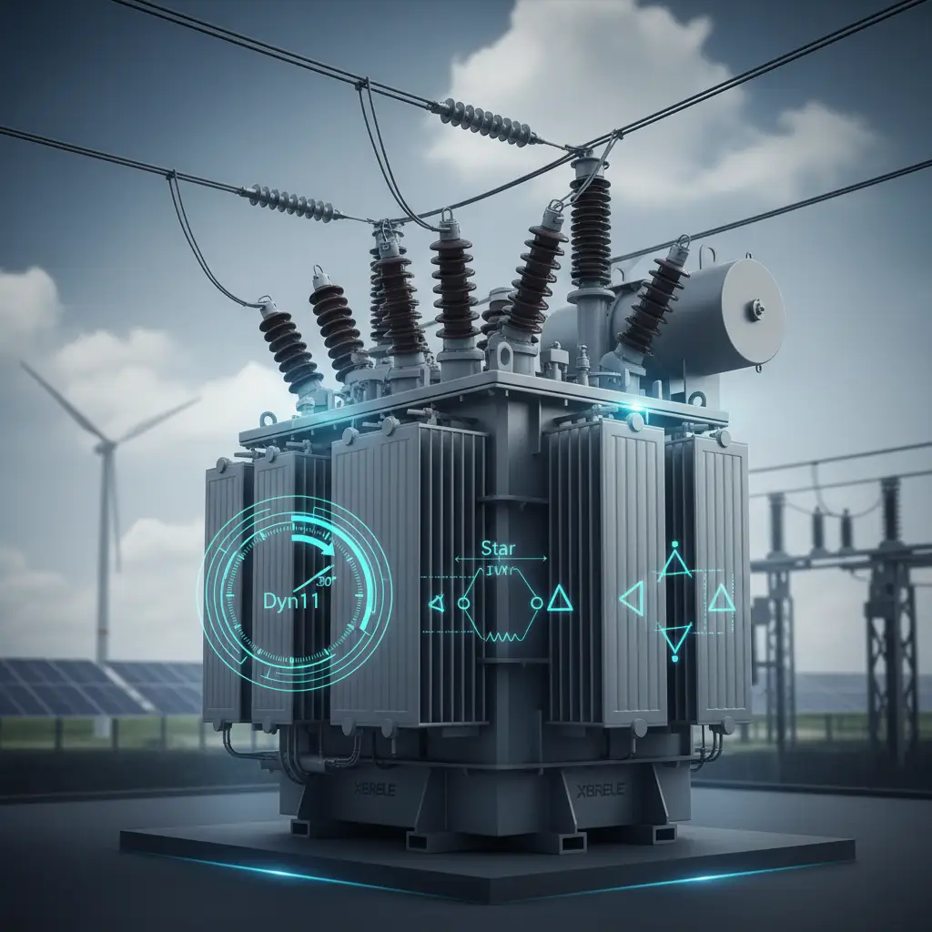
<p>Vector groups define the phase displacement between the High-Voltage (HV) and Low-Voltage (LV) sides. This is a non-negotiable prerequisite for <strong>Parallel Operation</strong>.</p>
The vector group (e.g., Dyn11) uses a clock face analogy where the HV vector is fixed at 12 o’clock (0°). Each “hour” represents a 30° phase lag of the LV relative to the HV.
The Four Mandatory Rules for Parallel Operation:
Integrating Solar PV and Wind farms poses unique challenges. These systems often require specialized Step-Up Transformers to bridge the gap between generation and transmission voltages:
To ensure a 25+ year lifecycle, a rigorous diagnostic schedule is required:
During energization, transformers draw an inrush current up to 12× the rated current (In). This phenomenon requires sophisticated protection coordination.
XBRELE Vacuum Circuit Breakers (VCBs) are engineered with specific contact metallurgy to handle these transients. When paired with high-end protection relays using ANSI 87T (Differential) and ANSI 50/51 (Overcurrent) codes, our switchgear ensures that the transformer remains protected from internal faults while avoiding nuisance tripping during normal energization.
Q: Why does a transformer “hum”? A: This is <strong>Magnetostriction</strong>—the physical vibration of core laminations due to magnetic flux. Excessive noise usually indicates over-fluxing (high <i>V/f</i>) or mechanical loosening of core clamping bolts.
Q: Can I parallel a Yy0 and a Dd0 transformer? A: Yes, as both belong to Group I (0° shift). However, all other parameters like %Z and voltage ratio must match.
Precise selection of Vector Groups and coordination with high-quality switching technology is essential for grid resilience. At XBRELE, we provide IEC-certified VCBs and protective components designed to keep critical power assets running safely.
Master the complexities of magnetic flux balance, Dyn11 vector group DNA, and the four golden rules of parallel operation. This IEC-compliant guide is essential for substation design and ensuring grid stability.
Download Technical Guide