Need Full Specifications?
Download our 2025 Product Catalog for detailed drawings and technical parameters of all switchgear components.
Get Catalog
Download our 2025 Product Catalog for detailed drawings and technical parameters of all switchgear components.
Get Catalog Download our 2025 Product Catalog for detailed drawings and technical parameters of all switchgear components.
Get Catalog
Quick Takeaway (Field Reading Order)
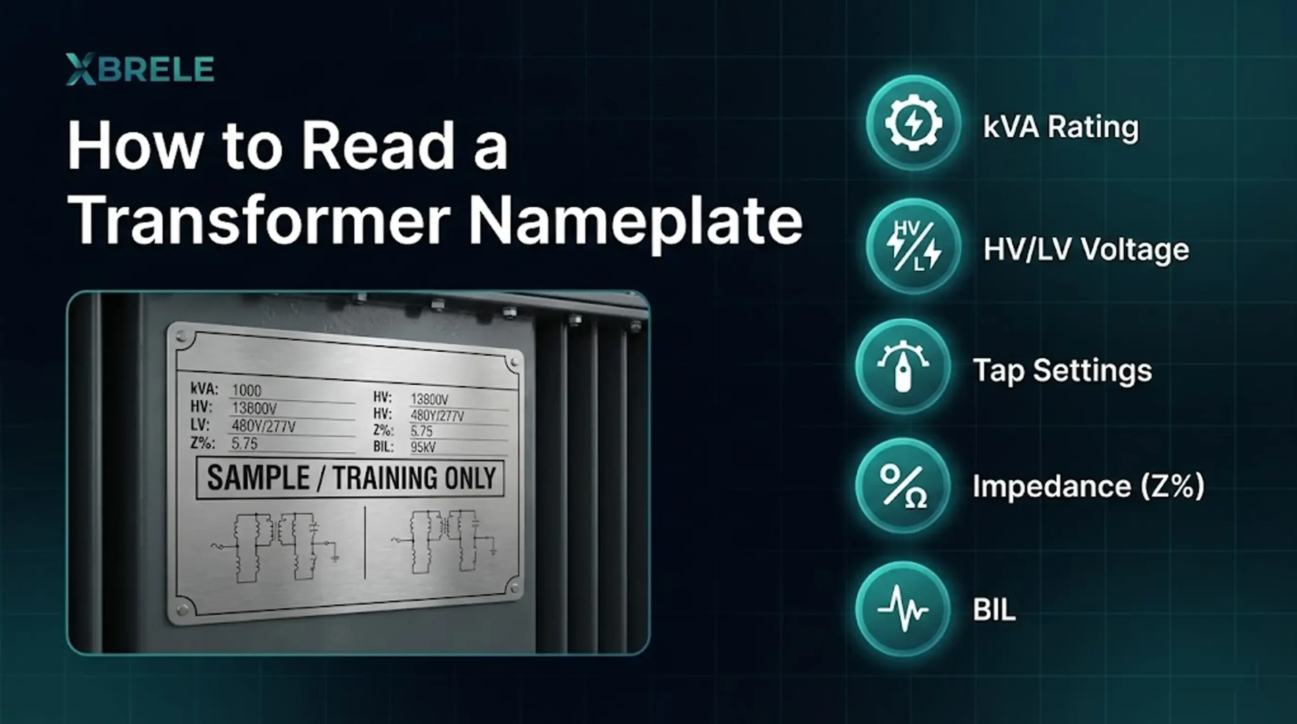
Read a transformer nameplate in the same order you make decisions on site: kVA → HV/LV voltage → tap setting → current sanity-check → frequency → cooling & temperature rise → impedance (Z%) & BIL → connection diagram. This sequence prevents the most common real-world mistakes (wrong voltage, wrong tap, wrong grounding assumptions).
Tip: If you only have 60 seconds, follow the checklist near the end of this guide before energizing.
Transformers don’t fail because someone forgot a definition. They fail because someone energized the wrong voltage, ignored tap position, assumed 50/60 Hz doesn’t matter, or sized cables and protection without understanding current and impedance.
A transformer nameplate isn’t decoration—it’s the unit’s minimum safe operating identity card. If you can read it confidently, you reduce the risk of wiring errors, overheating, nuisance trips, and premature failures.
Before you begin: If you want a quick foundation before diving into nameplates, check out: Electric Transformer Explained (2025 Edition)
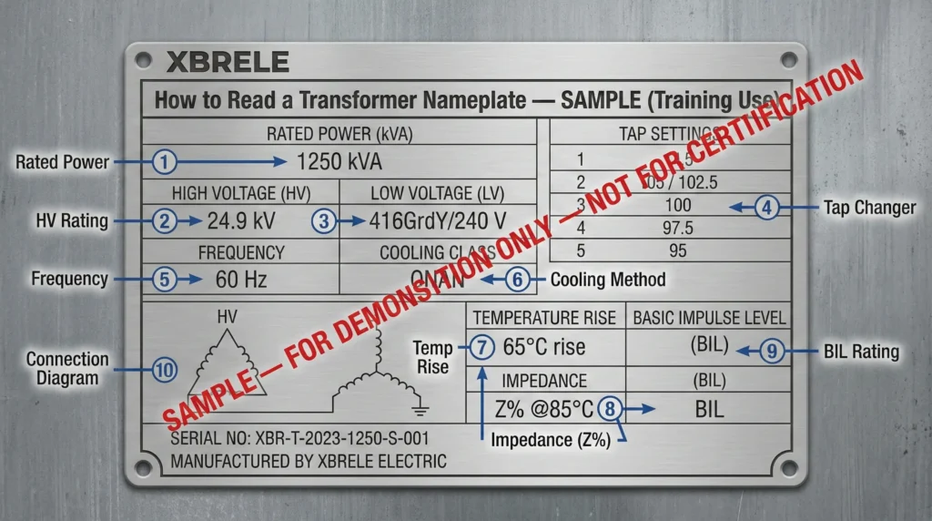
Most confusion comes from reading a nameplate “top to bottom” like a random table. In the field, you read it in a decision order:
Rating → Voltages → Tap settings → Current sanity-check → Frequency/phase → Cooling/thermal → Impedance/BIL → Connection diagram → Protection hardware (if shown)
That’s exactly what we’ll do below.
The first number that matters is the rating:
Transformers are rated in kVA (apparent power) because heating is driven mainly by voltage and current. kW depends on load power factor, which changes with the load—not with the transformer itself.
Field Takeaway: kVA is your baseline for “How much can I carry continuously?” Don’t treat it as a suggestion.
This is where most expensive mistakes begin.
Typical format:
How to read “416 GrdY / 240 V” in plain English:
Field Takeaway: This line tells you whether the system is three-wire or four-wire, whether neutral is available, and how the output is intended to be used. For more on distribution formats, see: What Is a Distribution Transformer?
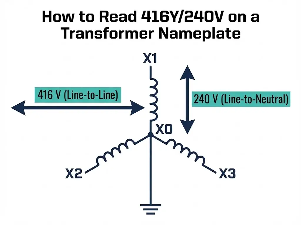
Many “mystery undervoltage” cases are simply wrong tap positions.
Tap table examples look like:
Think of taps as ratio fine-tuning:
Field Takeaway: If the transformer was recently serviced, always re-check the tap position before energizing.
Even if current isn’t listed, you can estimate it quickly to catch wrong assumptions fast.
For 3-phase systems:
Example for 1250 kVA:
Why this matters:
For deeper technical details on connection logic, see: 3-Phase Transformer Technical Guide
kVA → Current Calculator (Quick Sanity-Check)
Estimate transformer current for 3-phase or 1-phase systems (approx.).
Formula: I ≈ (kVA × 1000) / (√3 × VLL) for 3-phase, and I ≈ (kVA × 1000) / V for 1-phase. This is a quick estimate—final design must follow applicable standards, installation method, ambient temperature, harmonics, and protection coordination.
Typical values:
Field Takeaway: Frequency is not an optional spec. It affects core flux and heating behavior. Treat it as a must-match item unless an engineer explicitly states otherwise.
Transformers usually fail due to heat and insulation aging rather than “old age.”
Common cooling codes:
Temperature rise is often listed like:
Field Takeaway: Cooling limits tell you what the unit assumes about heat removal. Poor ventilation, high ambient temperature, and enclosure restrictions can push the unit harder than it appears on paper. For oil-filled units, check: Transformer Oil Technical Guide
Example format:
Why it matters:
Simple intuition:
BIL relates to surge withstand (lightning or switching impulses) and is part of insulation coordination.
Authoritative standard bodies:
When the text is confusing, the connection diagram typically answers the final questions:
Field Takeaway: Many commissioning mistakes start with wrong assumptions about neutral and grounding. The connection diagram is your most reliable sanity check.
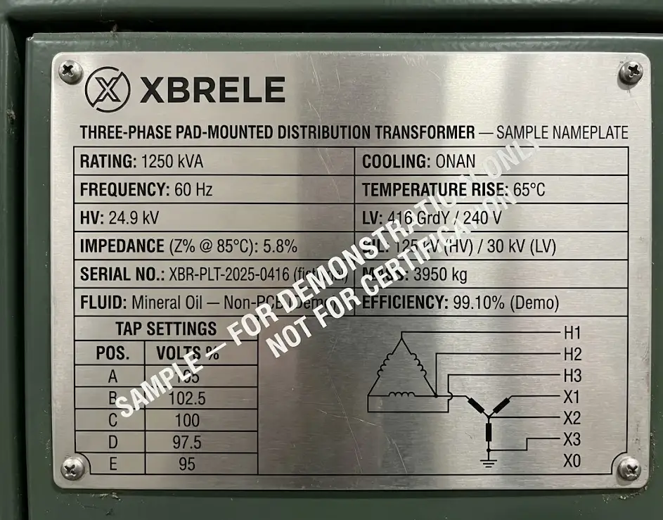
! Figure 2: Real-world nameplate example for verification practice.
| Document | Best For | Trust Level |
|---|---|---|
| Nameplate | Installation, Energization, & Inspection | Actual Identity of the Unit |
| Datasheet | Early Selection & Planning | Series-Level Capabilities |
| Test Report | Troubleshooting & Baseline Verification | Measured Performance Data |
Verify these eight items before turning on the power:
Why is kVA used instead of kW? Transformer heating is driven by voltage and current (apparent power). kW depends on the load’s power factor.
What does “GrdY” mean? Grounded wye. It indicates a neutral point exists and should be grounded per system design.
What does Z% @ 85°C change?
It affects fault current expectations, voltage regulation under load, and protection coordination assumptions.
Once you read a nameplate in the field-priority order—Rating → Voltages → Taps → Current → Frequency → Cooling → Impedance → Diagram—it stops being a wall of text and becomes a vital safety tool.
Recommended Next Read: Dry Type vs Oil Filled Transformers: Key Differences Explained
If you are selecting or replacing a distribution transformer, always verify the final unit configuration from the nameplate and supporting test documents. For engineering support and OEM transformer solutions, contact XBRELE.