Need Full Specifications?
Download our 2025 Product Catalog for detailed drawings and technical parameters of all switchgear components.
Get CatalogDownload our 2025 Product Catalog for detailed drawings and technical parameters of all switchgear components.
Get CatalogDownload our 2025 Product Catalog for detailed drawings and technical parameters of all switchgear components.
Get Catalog
XBRELE’s Earthing Switches (JN15 & EK6 Series) provide reliable safety grounding for KYN28/KYN61 switchgear. Featuring robust short-circuit making capacity up to 80kA (peak) and full compliance with IEC 62271-102 standards.
[cite_start]XBRELE JN15 and EK6 Series serve as the definitive personnel protection interface within distribution cabinets[cite: 1359, 1360]. [cite_start]These indoor mechanical devices establish a solid, visible connection to earth for 12kV, 24kV, and 40.5kV systems, enabling safe access during maintenance intervals[cite: 1399, 1491].
[cite_start]Engineered for fault tolerance, our make-proof safety units feature a rapid spring-operated mechanism capable of handling peak currents up to 80kA[cite: 1377]. This robust construction guarantees mechanical integrity even if closed onto a live fault, containing potential arc energy to protect operators.
Fully compliant with IEC 62271-102 Standards [cite_start], these switchgear components offer Class M1 mechanical endurance[cite: 1386]. [cite_start]They are designed for precise integration with chassis interlocks in KYN28 and KYN61 panels, preventing accidental operation while the main circuit is live[cite: 1399, 1491].
For VCB chassis, insulators, and other MV accessories, please visit our main Switchgear Parts & Accessories pillar page .
Full range of grounding switches (12kV to 40.5kV) compliant with IEC 62271-102. Select a series below to view detailed electrical ratings and complete dimension tables.

The JN15-12 series is an advanced indoor grounding switch meeting GB1985-2004 and IEC 62271-102 standards. Designed for 3~12kV three-phase AC systems.
It features high short-circuit making capability (80kA peak) to protect equipment against accidental energization.
The table below summarizes the rated electrical parameters.
Main technical parameters — JN15-12
| No. | Item | Unit | JN15-12/31.5 |
|---|---|---|---|
| 1 | Rated voltage | kV | 12 |
| 2 | Rated short-time withstand current (4s) | kA | 31.5 |
| 3 | Rated short-circuit making current (peak) | kA | 80 |
| 4 | Rated peak withstand current | kA | 80 |
| 5 | Rated insulation level (PF/Lightning) | kV | 42 / 75 |
| 6 | Mechanical life | Times | 2,000 |
Mounting Dimensions & Phase Spacing
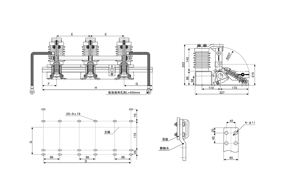
| Model Code | Phase Spacing (E) | Overall Width (H) | Mounting (F) | Mounting (G) | Mounting (D) |
|---|---|---|---|---|---|
| JN15-12/31.5-165 | 165 mm | 565 mm | 75 mm | 160 mm | 426 mm |
| JN15-12/31.5-180 | 180 mm | 595 mm | 75 mm | 160 mm | 456 mm |
| JN15-12/31.5-200 | 200 mm | 635 mm | 75 mm | 160 mm | 496 mm |
| JN15-12/31.5-210 | 210 mm | 655 mm | 75 mm | 160 mm | 516 mm |
| JN15-12/31.5-220 | 220 mm | 675 mm | 75 mm | 160 mm | 536 mm |
| JN15-12/31.5-230 | 230 mm | 695 mm | 75 mm | 160 mm | 556 mm |
| JN15-12/31.5-250 | 250 mm | 735 mm | 75 mm | 160 mm | 596 mm |
| JN15-12/31.5-275 | 275 mm | 810 mm | 75 mm | 185 mm | 646 mm |
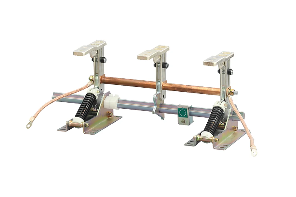
The EK6-12 series is designed based on the ES1 prototype grounding switch. It features a simplified assembly structure while maintaining full compliance with GB1985-2004 and IEC129 requirements.
This model is ideal for compact switchgear designs or retrofitting projects where an ES1-style footprint is required. It provides the same robust 31.5kA protection as the JN15 series.
See technical specifications below.
Main technical parameters — EK6-12
| No. | Item | Unit | EK6-12/31.5 |
|---|---|---|---|
| 1 | Rated voltage | kV | 12 |
| 2 | Rated short-time withstand current (4s) | kA | 31.5 |
| 3 | Rated short-circuit making current | kA | 80 |
| 4 | Rated peak withstand current | kA | 80 |
| 5 | Mechanical life | Times | 2,000 |
| 6 | Structure Type | – | Assembly (ES1 Based) |
Installation Note

EK6-12 is typically available in standard phase spacings (e.g., 210mm) similar to the JN15 series. Please verify mounting interface compatibility with ES1-type designs before ordering.

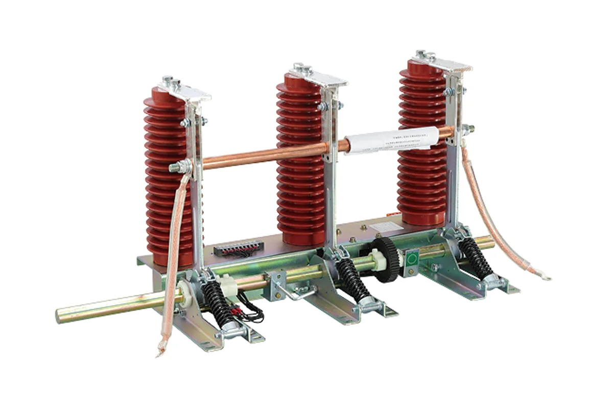
The JN15-24/31.5 is an upgraded version developed on the basis of the JN15-12. It maintains the same compact installation dimensions while providing insulation levels suitable for 24kV power systems.
Suitable for KYN28-24 switchgear, it ensures operator safety during maintenance with a robust short-circuit closing capability of 80kA.
Refer to the table below for insulation levels and current ratings.
Main technical parameters — JN15-24
| No. | Item | Unit | JN15-24/31.5 |
|---|---|---|---|
| 1 | Rated voltage | kV | 24 |
| 2 | Rated short-time withstand current (4s) | kA | 31.5 |
| 3 | Rated short-circuit making current | kA | 80 |
| 4 | PF withstand voltage (1 min) | kV | 65 |
| 5 | Lightning impulse withstand voltage | kV | 125 |
| 6 | Mechanical life | Times | 2,000 |
Mounting Dimensions (24kV)
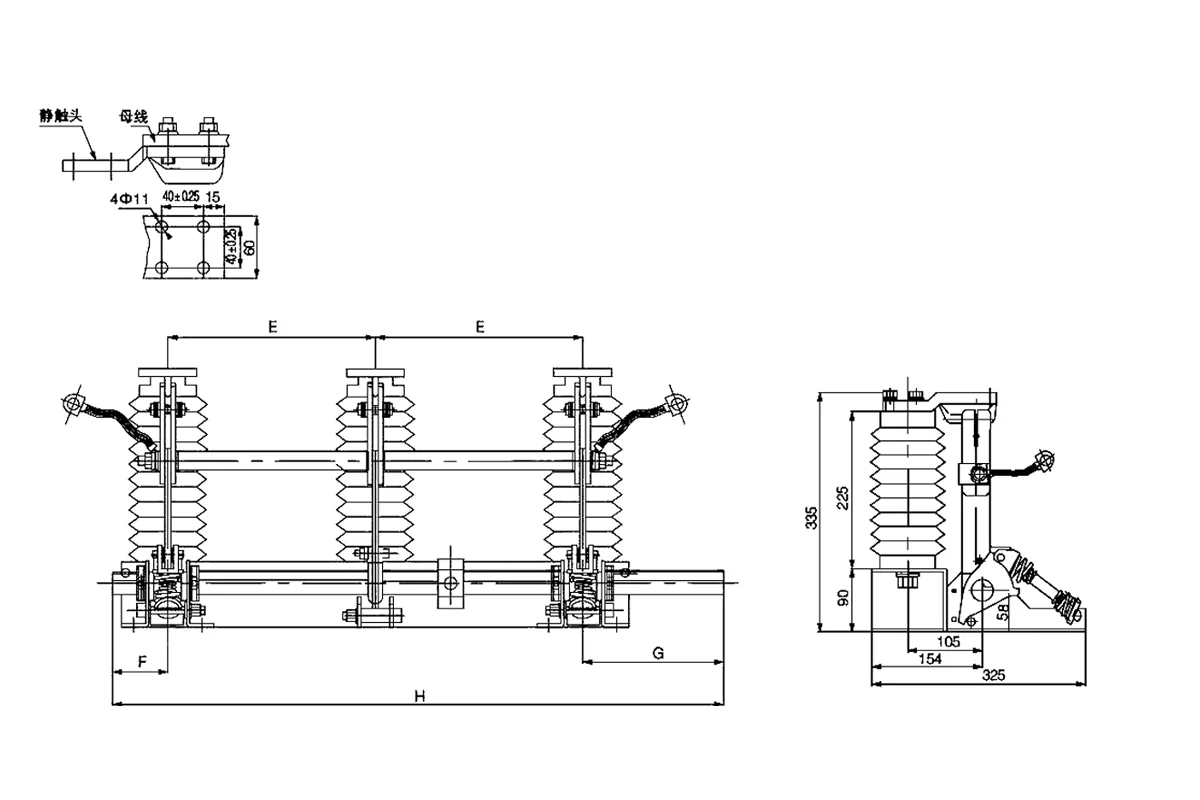
| Model Code | Phase Spacing (E) | Overall Width (H) | Mounting (D) | Mounting (C) |
|---|---|---|---|---|
| JN15-24/31.5-210 | 210 mm | 655 mm | 516 mm | 96 mm |
| JN15-24/31.5-220 | 220 mm | 675 mm | 536 mm | 96 mm |
| JN15-24/31.5-230 | 230 mm | 695 mm | 556 mm | 96 mm |
| JN15-24/31.5-250 | 250 mm | 735 mm | 596 mm | 96 mm |
| JN15-24/31.5-275 | 275 mm | 810 mm | 646 mm | 96 mm |
The JN22-40.5 is a high-performance grounding switch developed by the Xi’an High Voltage Apparatus Research Institute. It is specifically designed for 40.5kV AC 50Hz power systems.
Compatible with KYN61-40.5 cabinets, it serves as critical grounding protection during equipment overhaul. It features a robust structure to handle the larger clearance requirements of 35kV/40.5kV systems.
Suitable for environments without flood, explosion hazards, or severe dust.
Main technical parameters — JN22-40.5
| No. | Item | Unit | JN22-40.5/31.5 |
|---|---|---|---|
| 1 | Rated voltage | kV | 40.5 |
| 2 | Rated short-time withstand current (4s) | kA | 31.5 |
| 3 | Rated short-circuit making current | kA | 80 |
| 4 | Rated peak withstand current | kA | 80 |
| 5 | Lightning impulse withstand voltage | kV | 185 |
| 6 | Application Cabinet | Type | KYN61-40.5 |
Phase Spacing Dimensions (40.5kV)
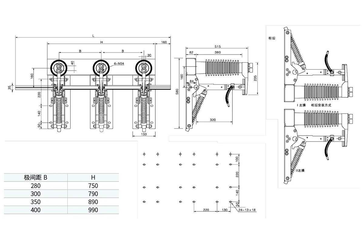
| Model Code | Phase Spacing (E) | Overall Width (H) |
|---|---|---|
| JN22-40.5/31.5-280 | 280 mm | 750 mm |
| JN22-40.5/31.5-300 | 300 mm | 790 mm |
| JN22-40.5/31.5-350 | 350 mm | 890 mm |
| JN22-40.5/31.5-400 | 400 mm | 990 mm |
Safety is paramount in MV power distribution. XBRELE High Voltage Grounding Switches are engineered with high short-circuit making capacity to protect personnel and equipment. Our products fully comply with IEC 62271-102 standards. For more details on compatible cabinets, visit our Switchgear Parts pillar page .
The most critical feature of a maintenance grounding switch is its ability to close safely onto a live fault. We ensure maximum operator protection.
Designed for frequent operation in distribution substations, our JN15 series utilizes advanced spring mechanisms for consistent performance.
Our indoor MV grounding devices are designed to integrate seamlessly into modern smart switchgear environments (KYN28/Unigear).
Reliability is non-negotiable for safety devices. XBRELE employs a rigorous 5-stage assembly and calibration process to ensure every JN15 unit meets the strict mechanical endurance and short-circuit capability requirements of IEC standards.
Unlike static components, this mechanical device requires precise calibration of spring tension and contact alignment to guarantee snap-action performance during critical faults.
Copper blades and contacts are tested for conductivity (%IACS) to ensure they can handle high thermal stress (31.5kA) without overheating.
The operating springs are calibrated to provide the exact torque required for high-speed closing, independent of operator speed.
Technicians adjust the phase distance and blade trajectory to ensure perfect alignment with the static contacts on the busbar system.
Every switch assembly undergoes 50 cycles of open/close operations to verify smooth mechanical action and interlock functionality.
A micro-ohm resistance test is conducted across the conductive path to ensure minimal power loss and stable electrical connection.
We strictly adhere to IEC 62271-102 protocols. Each safety component is verified for mechanical life and short-circuit making capability before dispatch.
XBRELE ensures rapid delivery of JN15 & EK6 assemblies to panel builders worldwide. We coordinate dimension customization, soft connection sizing, and secure export packaging to support urgent KYN28 production and retrofit projects.
We maintain a strategic inventory of common specifications (like 210mm and 275mm phase spacing) to minimize downtime for cabinet maintenance.
Beyond standard catalogs, XBRELE offers customization for non-standard HV mechanical requirements, ensuring seamless integration.
Heavy-duty switchgear accessories require robust protection. We use reinforced plywood cases to prevent damage to the operating shaft and insulators during transit.
Technical answers regarding JN15/EK6 selection, short-circuit capabilities, mechanical interlocks, and installation compatibility with KYN28 switchgear cabinets.