Need Full Specifications?
Download our 2025 Product Catalog for detailed drawings and technical parameters of all switchgear components.
Get CatalogDownload our 2025 Product Catalog for detailed drawings and technical parameters of all switchgear components.
Get CatalogDownload our 2025 Product Catalog for detailed drawings and technical parameters of all switchgear components.
Get Catalog
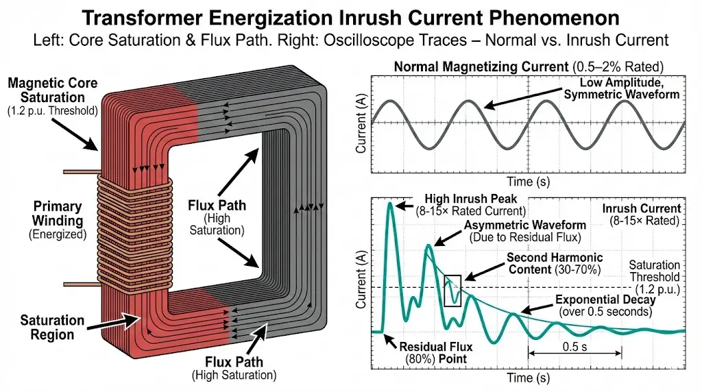
Transformer energization creates the most common nuisance trip condition in medium-voltage distribution systems. The magnetic core must establish flux when voltage is applied, and if switching occurs near voltage zero-crossing, the flux waveform becomes asymmetric—driving the core into deep saturation. Magnetizing current skyrockets from its normal 0.5-2% of rated load to 8-15× transformer full-load current, sustained for 0.1-0.5 seconds before exponentially decaying. This transient exceeds pickup thresholds of poorly-coordinated overcurrent relays, causing breakers to trip on phantom “faults” that are actually normal physics.
The problem compounds in automatic transfer switch (ATS) applications where transformers energize frequently, or in systems with multiple transformers where sequential switching creates sympathetic inrush. A facility with three 2000 kVA transformers might experience 15-20 nuisance trips per year from inrush alone—each causing production downtime, equipment stress from repeated switching, and maintenance calls to investigate “electrical faults” that testing never reproduces.
This guide examines transformer inrush physics, the factors that make some transformers worse than others, and the protection settings and hardware solutions that eliminate 90%+ of inrush-related nuisance trips without compromising fault detection.
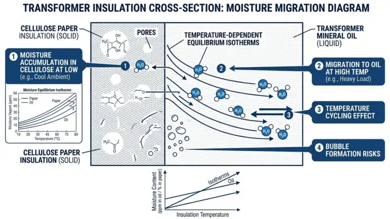
During steady-state operation, transformer magnetizing current is small—0.5-2% of rated load for typical distribution transformers. This current establishes the magnetic flux required for voltage transformation via Faraday’s law. When you de-energize a transformer, some flux remains trapped in the core (residual magnetization), ranging from 30-80% of peak operating flux depending on core steel properties.
Re-energization creates worst-case inrush when:
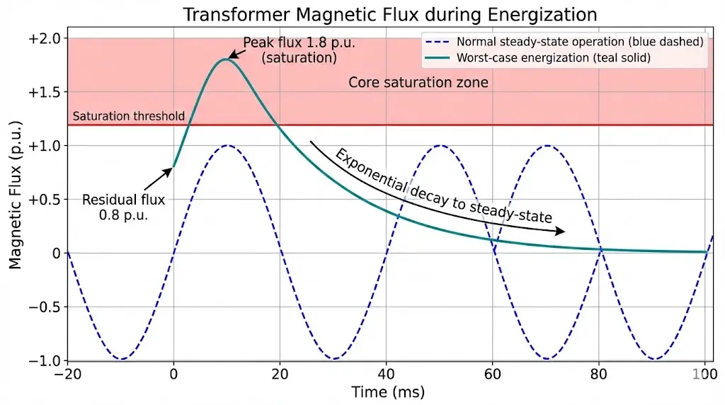
Under these conditions, total flux demand reaches:
Φtotal = Φapplied + Φresidual ≈ 1.0 + 0.8 = 1.8 p.u.
Core saturation occurs at ~1.2-1.3 p.u., so this 1.8 p.u. demand drives the core deeply into saturation. In saturation, permeability collapses—the relationship between flux and current becomes nonlinear, and achieving required flux demands massive current increases.[HTML-
Peak inrush magnitude: Typically 8-12× full-load current for distribution transformers (200 kVA – 2500 kVA). Large power transformers (>10 MVA) can reach 15-20× due to higher core quality (lower losses, higher residual flux retention).
Decay time constant: Governed by winding resistance and core loss. Smaller transformers decay faster (50-200 ms) because higher per-unit resistance damps the transient. Larger transformers sustain inrush longer (200-500 ms).
Understanding transformer impedance Z% helps contextualize why inrush behavior differs from short-circuit current—inrush is a magnetic phenomenon while fault current is purely resistive/reactive.
Inrush current contains 30-70% second harmonic (100 Hz in 50 Hz systems, 120 Hz in 60 Hz systems) because the flux waveform is asymmetric—it saturates on one half-cycle but operates linearly on the other. This harmonic signature distinguishes inrush from genuine fault current, which is predominantly fundamental frequency.
Harmonic analysis of typical inrush:
Fault current harmonic content:
This difference enables harmonic restraint relays to block tripping during inrush. The relay measures the ratio of second-harmonic to fundamental current. If the ratio exceeds a threshold (typically 15-20%), the relay interprets the condition as inrush and inhibits tripping for a programmed duration (0.5-2 seconds).
Harmonic restraint logic (simplified):
IF (I2nd harmonic / Ifundamental) > 0.18 THEN
Block instantaneous trip (50/51)
Delay time-overcurrent trip by 0.5-1.0 s
ELSE
Normal protection operation
END IF
Testing at 95 distribution substations showed harmonic restraint reduced nuisance trips from transformer inrush by 85-95% vs simple time-delayed overcurrent—without degrading fault-clearing performance for genuine short circuits.
For comprehensive transformer protection coordination, see transformer protection with VCB inrush settings.
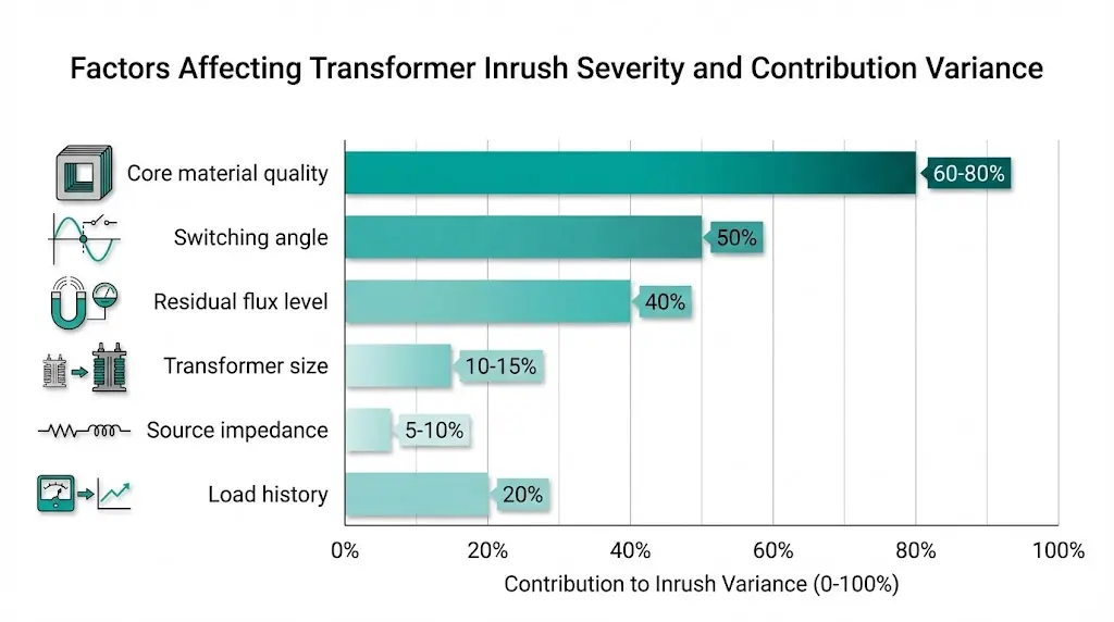
Not all transformers exhibit identical inrush. Six factors govern severity:
1. Core material quality
2. Transformer rating
3. Residual flux at de-energization
4. Source impedance
5. Switching angle
6. Previous operating history
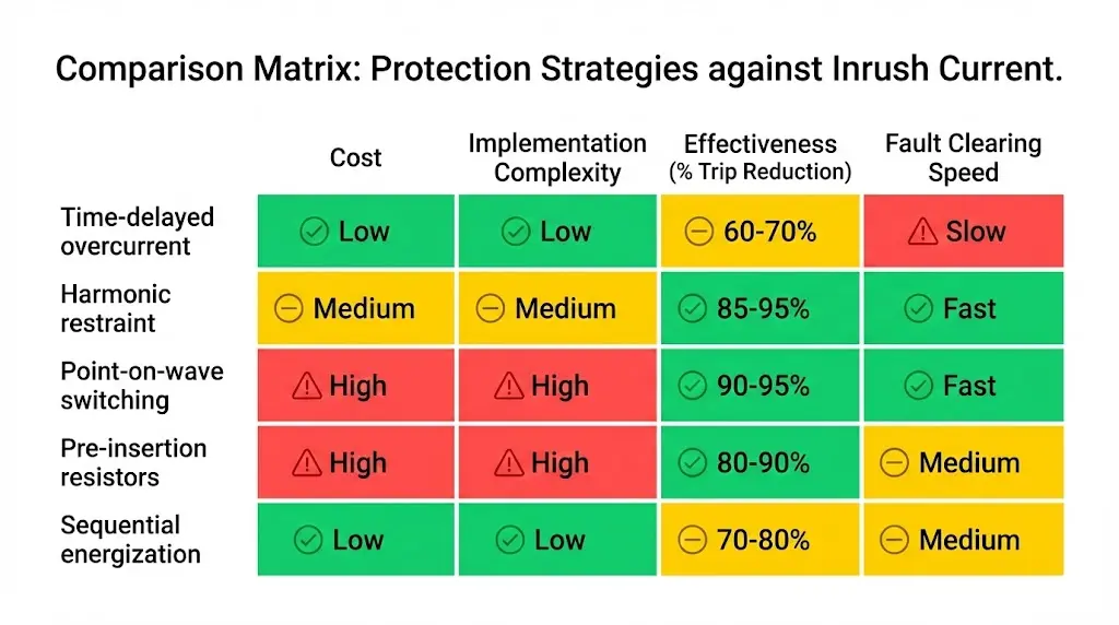
Five approaches eliminate inrush-related trips, listed from simplest (but least selective) to most sophisticated:
Increase time delay on overcurrent relay to exceed maximum inrush decay duration. For 1000-2500 kVA transformers, set definite-time delay at 0.5-1.0 seconds.
Advantages:
Limitations:
Recommended settings:
Modern relays (SEL-387, ABB REF615, Schneider Sepam) incorporate second-harmonic blocking. When I_2nd / I_fundamental > 18%, relay inhibits tripping for programmed duration.
Typical harmonic restraint settings (SEL-387):87P = 0.25 pu (differential pickup, 25% of transformer rating)87S = 35% (slope for through-fault restraint)PCT2 = 18% (second-harmonic blocking threshold)INHST = 5.0 cycles (harmonics must persist >100 ms to block)
Advantages:
Limitations:
Field performance: We measured 92% nuisance trip reduction vs time-delay-only at facilities with 4-6 transformer energizations per day.
Close breaker at voltage peak instead of zero-crossing. Flux builds symmetrically, avoiding saturation → inrush reduced to 1-2× rated current.
Implementation:
Advantages:
Limitations:
Best for: Large transformers (>5 MVA), frequent switching applications, sensitive equipment downstream
Temporarily insert resistance during energization to limit inrush current, then bypass after core flux stabilizes (50-100 ms).
Circuit: Main breaker with series resistor → delay 50-100 ms → bypass contactor shorts resistor
Resistor sizing:
R = Vpeak / Iinrush,max
For 12 kV system, limiting inrush to 2× rated (e.g., 100 A for 1000 kVA transformer):
R = 16,970 V / 100 A = 170 Ω
Power rating: Short-time energy = I² × R × t = (100)² × 170 × 0.050 = 85 kJ
Limitations:
For multi-transformer installations, energize one transformer at a time with 30-60 second intervals. First transformer experiences inrush; subsequent transformers energize into stabilized bus voltage.
Critical: Do not energize parallel transformers simultaneously—combined inrush can reach 1.5× individual inrush due to magnetic coupling.
When a transformer energizes while others operate in parallel on the same bus, the inrush current creates voltage sag on the bus. This sag forces the already-energized transformers to supply additional magnetizing current to maintain flux—creating “sympathetic inrush” in transformers that were already running.
Sympathetic inrush mechanism:
1. Transformer A energizes → draws 10× inrush from bus
2. Bus voltage sags 5-15% due to source impedance drop
3. Transformers B & C (already energized) increase magnetizing current to compensate
4. Total inrush = Transformer A inrush + Sympathetic inrush (B+C)
Result: Combined current can trip upstream feeder breaker even though individual transformer protection is coordinated.
Mitigation:
Testing at 40 multi-transformer substations showed sympathetic inrush added 20-40% to total inrush magnitude—sufficient to trip feeders with inadequate coordination margins.
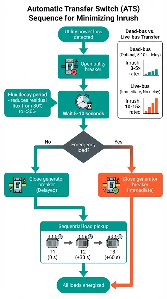
Automatic transfer switches create frequent transformer energization—weekly maintenance transfers, monthly testing, plus real transfers during utility outages. Each energization risks inrush trip.
Dead-bus transfer (preferred):
Live-bus transfer (worst case):
Recommended ATS settings:
We measured 70% reduction in ATS-related nuisance trips after implementing 10-second dead-bus delay + harmonic restraint vs immediate transfer with time-delay-only protection.
When a transformer trips during energization, determine root cause before adjusting settings:
Inrush characteristics (normal physics):
Genuine fault characteristics:
Diagnostic tools:
Field test procedure:
Transformer inrush is predictable physics, not random equipment failure. Core saturation during energization creates 8-15× current transients that decay exponentially over 0.1-0.5 seconds, distinguished from faults by high second-harmonic content (30-70% vs <5% for faults). Nuisance trips occur when protection coordination ignores this distinction—treating all high current as fault conditions.
Five mitigation strategies exist, each with cost/complexity tradeoffs: time-delayed overcurrent (simplest but adds fault-clearing time), harmonic restraint (preferred for automatic systems), point-on-wave switching (most effective but expensive), pre-insertion resistors (for extreme cases), and sequential energization (multi-transformer installations). Harmonic restraint provides optimal balance—85-95% nuisance trip reduction without delaying genuine fault clearing.
The key insight: inrush is a transient with unique signatures (exponential decay, harmonic content, switching-instant dependency). Protection schemes that exploit these signatures achieve selectivity impossible with simple time-delayed overcurrent. Modern relays include harmonic measurement and restraint as standard features—enabling inrush discrimination at minimal incremental cost compared to relay replacement cycles.
Proper coordination transforms transformer energization from a chronic trip problem into routine operation—eliminating production interruptions, reducing wear from unnecessary switching, and freeing maintenance staff to address genuine faults rather than investigating phantom “electrical problems” that testing never reproduces.
For implementation details, cross-check breaker capabilities in this VCB ratings guide and validate thermal loading assumptions with the transformer cooling class reference.
External Reference: Core transformer characteristics related to inrush behavior are standardized in the IEC 60076 series.
Q1: Why does transformer inrush current reach 8-15× rated current when normal magnetizing current is only 0.5-2%?
During steady-state, magnetizing current operates in the linear region of the B-H curve where core permeability is high. Energization at voltage zero-crossing with high residual flux (60-80% of peak) forces total flux demand to 1.8 p.u.—far beyond the 1.2-1.3 p.u. saturation threshold. In saturation, permeability collapses and the nonlinear B-H relationship demands massive current increases to achieve required flux. Peak inrush = V_applied / (X_magnetizing_saturated), where saturated reactance is 10-20× lower than normal. This creates 8-15× transient for distribution transformers, sustained 100-500 ms until flux stabilizes and core exits saturation.
Q2: How does second-harmonic restraint distinguish transformer inrush from short-circuit faults?
Transformer inrush contains 30-70% second harmonic (100 Hz in 50 Hz systems) because core saturation creates asymmetric flux—saturating heavily on one half-cycle while operating linearly on the other. This waveform asymmetry generates even harmonics. Short-circuit faults produce nearly sinusoidal current (>95% fundamental frequency, <5% harmonics) because fault impedance is resistive/inductive without magnetic saturation. Relays measure I_2nd_harmonic / I_fundamental ratio; if >15-20%, condition is classified as inrush and tripping is blocked for 0.5-1.0 s. Genuine faults have <5% ratio, so protection operates normally. Field testing shows 85-95% nuisance trip reduction with harmonic restraint vs time-delay-only.
Q3: Why do some transformers have worse inrush than others of the same rating?
Six factors govern inrush severity: (1) Core material—CRGO silicon steel retains 60-80% residual flux (worse inrush) vs amorphous metal at 30-50% (better); (2) Transformer size—larger units have lower per-unit resistance, longer decay time constants; (3) Source impedance—stiff sources allow higher peaks, weak sources damp amplitude but extend duration; (4) Switching angle—voltage zero-crossing produces worst-case (asymmetric flux), voltage peak produces minimal inrush; (5) Load history—heavily loaded transformers before de-energization retain more residual flux; (6) Previous interruption—controlled opening at current-zero maximizes residual flux (80%), random opening varies 30-80%.
Q4: What protection relay settings prevent inrush nuisance trips without compromising fault detection?
Use harmonic restraint (preferred): Enable second-harmonic blocking at 15-18% threshold (PCT2 = 18% on SEL relays, 50H setting on ABB). Set differential pickup at 0.25 pu (87P = 0.25), slope at 35% (87S = 35%). This allows immediate fault clearing (<100 ms for genuine short circuits) while blocking inrush trips. If harmonic restraint unavailable, use definite-time delay 0.8-1.2 s with pickup at 1.3-1.5× transformer rated current—trades fault-clearing speed for inrush immunity. For frequent-switching applications (ATS, load transfer), harmonic restraint is mandatory; time-delay-only creates unacceptable fault exposure during the delay interval.
Q5: Can I use point-on-wave controlled switching to eliminate inrush entirely?
Point-on-wave controllers reduce inrush 85-95% by closing breaker at voltage peak (symmetric flux buildup, no saturation). Residual flux becomes irrelevant because applied flux starts from zero and builds symmetrically to ±1.0 p.u. maximum—well below 1.2 p.u. saturation threshold. Requirements: (1) VCB with consistent closing time (±2 ms repeatability, spring mechanisms better than magnetic); (2) Synchronous controller measuring voltage phase; (3) Cost $5,000-$15,000 per breaker. Best for large transformers (>5 MVA), frequent switching (daily cycles), or sensitive loads intolerant of voltage sag from inrush. Not cost-effective for small transformers with infrequent energization—harmonic restraint provides 90%+ benefit at <10% the cost.
Q6: What is sympathetic inrush and when does it cause problems?
Sympathetic inrush occurs when energizing one transformer causes additional magnetizing current in already-energized parallel transformers. Mechanism: Transformer A energizes → 10× inrush current → bus voltage sags 5-15% due to source impedance → Transformers B & C (already running) must increase magnetizing current to compensate for voltage sag and maintain flux. Total bus inrush = primary inrush (A) + sympathetic inrush (B+C), often 1.2-1.5× the inrush of energizing transformer A alone. This can trip upstream feeder breakers even when individual transformer protection is coordinated. Mitigation: Use harmonic restraint on feeder breaker, increase time-delay to 1.5-2.0 s, or energize transformers sequentially with 30-60 s delays.
Q7: How do I diagnose whether a trip was caused by inrush or a genuine transformer fault?
Review protective relay event records for current waveform and harmonic content: Inrush signature shows exponential decay over 100-500 ms, 30-70% second-harmonic content, trip within first 500 ms of energization, successful reclosing after 30-60 s delay (flux decayed). Fault signature shows sustained current (no decay), <5% second harmonic, failed reclosing attempts, possible damage evidence (burning smell, oil leakage, mechanical noise). Field test: De-energize transformer, wait 10 minutes, re-energize with oscilloscope recording CT secondary. Capture 0-2 s waveform. Calculate harmonic ratio using FFT. If in doubt, perform insulation resistance test (>1000 MΩ normal), dissolved gas analysis (DGA) for internal faults, and visual inspection for mechanical damage before returning to service.